|
|

Table Of Contents
Cisco MPLS VPN Mapping of RFC 1483 Routed Sessions
Comparison of Conventional VPNs and MPLS VPNs
New Terminology for MPLS VPN Mapping of RFC 1483 Routed Sessions
Supported Standards, MIBs, and RFCs
Installing Cisco IOS Release 12.1(4)DA
Enabling Cisco Express Forwarding
Configuring a VPN Forwarding Routing Instance
Creating a Loopback Interface and Associating It with a VRF
Creating a Loopback Interface to be Associated with the Uplink Interface
Creating Uplink ATM Subinterfaces and VP Tunnels and Enabling MPLS
Configuring the PE to CE Interface
show tag-switching forwarding vrf
Cisco MPLS VPN Mapping of RFC 1483 Routed Sessions
This feature module describes the Cisco Multiprotocol Label Switching (MPLS) Virtual Private Network (VPN) Mapping of RFC1483 Routed Sessions feature for all Cisco Digital Subscriber Line Access Multiplexers (DSLAMs) using the second-generation network interface module (NI-2). It includes information this new feature and supported platforms. This features first appears in Cisco IOS Release 12.1(4)DA.
This document contains the following sections:
Feature Overview
The Cisco MPLS VPN Mapping of RFC 1483 Routed Sessions feature enables Cisco DSLAMs with NI-2 controller cards and connected customer premises equipment (CPE) to participate in MPLS VPNs. This feature promotes the rapid deployment of secure IP VPNs that enable revenue generating services such as:
•
Intranets
•
•
•
•
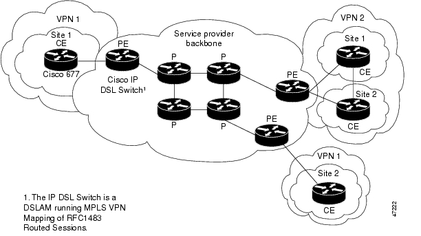
Figure 1 shows an example of an MPLS VPN with a service provider (P) backbone network, service provider edge routers (PE), and customer edge routers (CE).
Figure 1
VPNs with a Service Provider Backbone
Benefits
In local area networks (LAN), IP-based intranets have had an impact on the way companies conduct business. Companies meet the needs of their customers, suppliers, and partners by using extranets (an intranet that encompasses multiple businesses). Using extranets, companies reduce business process costs through supply-chain automation, electronic data interchange (EDI), and content hosting services. Virtual Private Networks address these needs by providing secure, private network services over the public Internet.
Cisco provides Layer 2 mechanisms that enable Service Providers (SPs) to deploy VPNs.To meet the scalability challenges inherent in provisioning fully-meshed Layer 2 VPNs, SPs must:
•
•
MPLS VPN Mapping of RFC 1483 Routed Sessions provides a solution to both of these problems:
1.
2.
The MPLS VPN mapping of RFC 1483 routed sessions also:
•
•
•
•
Comparison of Conventional VPNs and MPLS VPNs
Conventional VPNs
Conventional VPNs do not scale well. Layer 2 VPNs are provisioned by creating and maintaining a full mesh of tunnels or permanent virtual circuits among all sites belonging to a particular VPN, using:
•
•
•
•
•
•
The resources and equipment required to provision and manage connection-based schemes cannot be supported in an SP network that must support hundreds or thousands of VPNs, each with multiple sites and thousands or tens of thousands of routes.
MPLS VPNs
MPLS VPNs offer all of the value of traditional VPNs. Furthermore, since MPLS VPNs are created in Layer 3, they are more scalable, and easier to configure and manage than Layer 2 VPNs.
MPLS VPNs offer:
•
•
•
•
•
Supported MPLS Features
The following features are supported to deliver MPLS VPN Mapping of RFC 1483 Routed Sessions:
•
–
–
–
–
–
–
–
•
•
•
Restrictions
This section describes restrictions to Cisco MPLS VPN mapping of RFC 1483 routed sessions.
Number of Configurable MPLS VPNs Limited to 50
Each IP DSL switch can support up to 50 MPLS VPNs.
Integrated Routing and Bridging Not Supported
MPLS VPN mapping of RFC 1483 routed sessions must not be confused with Integrated Routing and Bridging (IRB). IRB is not supported by MPLS VPN mapping of RFC 1483 routed sessions.
VPN Interfaces Restricted to Trunk Interfaces
Do not configure subtended interfaces for MPLS VPN services. Only trunk interfaces support MPLS VPN mapping of RFC 1483 routed sessions.
MPLS ATM-Label Switch Router Functionality Not Supported
IP DSL switches are not meant for use as MPLS ATM-Label Switch Routers (ATM-LSRs). When designing your network, keep in mind that IP DSL switches act only as Label Edge Routers (LER).
Performance Restrictions for MPLS VPN Traffic
MPLS VPN-enabled interfaces do not perform as well as switched VCs. Please take this into consideration when deploying MPLS VPNs in your networks.
Restricted Layer 3 Services
The following Layer 3 services are not supported in Cisco IOS Release 12.1(4)DA:
•
•
•
Restricted MPLS Features
The following are MPLS-related features that are not a part of the MPLS VPN mapping of RFC 1483 routed sessions feature:
•
•
DSL Interface Limitations
In IP DSL switches, each DSL interface can support multiple Permanent Virtual Circuits (PVCs), but only one routed MPLS VC.
Configuration of MPLS VPN Mapping of RFC 1483 Routed Sessions not Supported by Cisco DSL Manager (CDM)
CDM users can provision switched VCs, but CDM does not support configuring routed termination of RFC 1483 sessions.
MPLS VPN Mapping of RFC 1483 Routed Sessions not Supported on the Eight-Port IDSL ITU-C Line Card
Routed termination of IDSL connections is not supported in Cisco IOS Release 12.1(4)DA.
Related Documents
•
•
•
•
New Terminology for MPLS
Table 1 lists old tag switching and more current MPLS terms:
New Terminology for MPLS VPN Mapping of RFC 1483 Routed Sessions
DSLAMs running the MPLS VPN mapping of RFC 1483 routed sessions feature are referred to as IP DSL switches.
Supported Platforms
The following DSLAM platforms support MPLS VPN mapping of RFC 1483 routed sessions:
•
•
•
•
Supported Standards, MIBs, and RFCs
MIB Support
No new or modified MIBs are supported by this feature.
RFC Support
•
•
•
•
Supported Standards
No new or modified standards are supported by this feature.
Configuration Prerequisites
Your network must be running the following services before you configure MPLS VPN mapping of RFC 1483 routed sessions:
•
•
•
•
•
•
Configuration Tasks
This section describes the configuration tasks for enabling MPLS VPN mapping on supported DSLAM platforms.
Configuring MPLS VPN mapping of RFC 1483 routed sessions is similar to configuring MPLS VPNs on other Cisco MPLS platforms. For general MPLS VPN configuration tasks, examples, and command references, consult the MPLS Virtual Private Networks and MPLS Virtual Private Network Enhancements feature modules.
To enable MPLS VPN Mapping of RFC 1483 Routed Sessions, perform the following configuration tasks:
•
•
•
•
•
•
•
•
Installing Cisco IOS Release 12.1(4)DA
Refer to the software installation documentation for the DSLAM platform on which MPLS VPN mapping of RFC 1483 routed sessions will be installed.
Enabling Cisco Express Forwarding
To enable Cisco Express Forwarding (CEF) on NI-2 based DSLAMs, enter the following command:
Command Usage Example
DSLAM(config)#ip cefDSLAM(config)#endDSLAM#Configuring a VPN Forwarding Routing Instance
To define VPN forwarding routing instances (VRFs), use the following commands in router configuration mode on a PE router:
Command Usage Example
DSLAM(config)#ip vrf vpn1DSLAM(config-vrf)#rd 100:1DSLAM(config-vrf)#route-target export 100:1DSLAM(config-vrf)#route-target import 100:1DSLAM(config-vrf)#endDSLAM#Creating a Loopback Interface and Associating It with a VRF
To create a loopback interface and associate it with a VRF, enter the following commands:
Command Usage Example
DSLAM(config)#interface Loopback1DSLAM(config-if)#ip vrf forwarding vpn1DSLAM(config-if)#ip address 6.6.6.6 255.255.255.255DSLAM(config-if)#endDSLAM#Creating a Loopback Interface to be Associated with the Uplink Interface
You should configure a loopback interface on DSLAMs running MPLS VPN mapping of RFC 1483 routed sessions configured for label switching. This virtual interface is always active.
The IP address you assign to the loopback interface is used as the Label Distribution Protocol (LDP) identifier for the IP DSL switch.
If a loopback interface:
•
•
Therefore, we recommend that you configure a loopback interface. You must associate the VRF with a routed interface using the following commands:
Command Usage Example
DSLAM(config)#interface Loopback0DSLAM(config-if)#ip address 172.16.1.6 255.255.255.255DSLAM(config-if)#endDSLAM#
Creating Uplink ATM Subinterfaces and VP Tunnels and Enabling MPLS
To create a VP tunnel from the MPLS uplink port to the Service Provider network, enter the following commands:
1.
DSLAM(config)#interface atm slot/portEnters interface configuration mode.
2.
DSLAM(config-if)#atm pvp vpiCreates the VP tunnel that connecting the uplink interface to the SP network.
Note
3.
DSLAM(config-if)#exitReturns to global configuration mode.
4.
DSLAM(config)#interface atm slot/port.vpi
point-to-point
Enters configuration mode for the PVP.
5.
DSLAM(config-subif)#ip unnumbered loopback
loopback_interface_number
Enables IP processing for this subinterface.
Note
6.
DSLAM(config-subif)#tag-switching ipEnables MPLS for IPv4 packets on this subinterface.
Command Usage Example
DSLAM(config)#interface ATM0/1DSLAM(config-if)#atm pvp 61DSLAM(config-if)#tag-switching ipDSLAM(config-if)#exitDSLAM(config)#interface ATM0/1.61 point-to-pointDSLAM(config-subif)#ip unnumbered Loopback0DSLAM(config-subif)#endDSLAM#
Configuring the PE to CE Interface
To create the PE to CE DSL interface and configure it for membership in an MPLS VPN, enter the following commands:
Command Usage Example
DSLAM(config)#interface ATM1/2DSLAM(config-if)#ip vrf forwarding vpn1DSLAM(config-if)#ip unnumbered Loopback1DSLAM(config-if)#pvc 1/32DSLAM(config-if-atm-vc)#encapsulation aal5snapDSLAM(config-if-atm-vc)#endDSLAM#Configuring Routing Sessions
This section describes the routing protocol configuration tasks necessary to enable MPLS VPNs in your network.
To configure an operational MPLS VPN, you must:
•
•
•
Configuring BGP Routing Sessions
To configure BGP routing sessions in a provider network, use the following commands in router configuration mode on the PE router:
Command Usage Example
DSLAM(config)# router bgp 100DSLAM(config-router)# neighbor 172.16.0.8 remote-as 100DSLAM(config-router)# neighbor 172.16.0.8 update-source Loopback0DSLAM(config-router)# address-family vpnv4DSLAM(config-router-af)# neighbor 172.16.0.8 send-community bothDSLAM(config-router-af)# neighbor 172.16.0.8 activateDSLAM(config-router-af)# exit-address-familyConfiguring MPLS Core Routing Protocols
Though there are several routing protocols to choose from, the configuration example below uses OSPF as an IGP:
For information on configuring other routing protocols, consult the Cisco IOS IP and IP Routing Command Reference for Cisco IOS Release 12.1.
Command Usage Example
DSLAM(config)#router ospf 6DSLAM(config-router)#network 172.16.0.0 0.0.255.255 area 0DSLAM(config-router)#endDSLAM#Configuring RIP PE to CE Routing Sessions
To configure BGP PE to CE routing sessions, use the following commands in router configuration mode on the PE router:
Command Usage Example
DSLAM(config)#router ripDSLAM(config-router)# address-family ipv4 vrf vpn1DSLAM(config-router-af)#redistribute bgp 100 metric transparentDSLAM(config-router-af)#network 6.0.0.0DSLAM(config-router-af)#exit-address-familyDSLAM(config-router)#endDSLAM#Verifying VPN Operation
To verify the proper operation of an MPLS VPN, use the following commands:
Configuration Samples
This section provides sample configurations of MPLS VPN Mapping of RFC 1483 Routed Sessions.
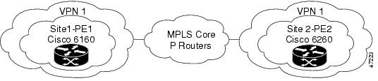
The configuration samples represent a simple hub-and-spoke network with two adjacent IP DSL switches. Figure 2 illustrates the network topology for the sample configurations below.
Note
!!!This is a comment.!!!Comments appear before the configurations they describe.Figure 2 Simple Hub and Spoke MPLS VPN Network Diagram
Site 1-PE1 Configuration—Cisco 6160 DSLAM
hostname dsl-6!boot system flash:ni2-dslp5-mz.ni2_mpls.20000720slot 1 ATUC-4FLEXIDMT!dsl-profile 4dmt2funcdmt training-mode standarddmt overhead-framing mode1dmt bitrate minimum interleaved downstream 8032 upstream 864dmt bitrate maximum interleaved downstream 8032 upstream 864!network-clock-select 1 systemip subnet-zero!!!!Define and configure the VRF. Refer to the "Configuring a VPN Forwarding Routing Instance" section.!!!ip vrf vpn1rd 100:1route-target export 100:1route-target import 100:1!!!!The following command enables Cisco Express Forwarding. See the "Enabling Cisco Express Forwarding" section.!!!ip cef!atm address 47.0091.8100.0000.0010.06ec.9102.0010.06ec.9102.00atm router pnnino aesa embedded-number left-justifiednode 1 level 56 lowestredistribute atm-static!!!!Create an uplink loopback interface. Refer to the "Creating a Loopback Interface to be Associated with the Uplink Interface" section.!!!!interface Loopback0ip address 172.16.1.6 255.255.255.255!!!!Configure a loopback interface and associate it with a VRF. Refer to the "Creating a Loopback Interface and Associating It with a VRF" section.!!!interface Loopback1ip vrf forwarding vpn1ip address 6.6.6.6 255.255.255.255interface ATM0/0no ip addressatm cac service-category abr denyatm maxvp-number 0atm maxvc-number 4096atm maxvci-bits 12!interface Ethernet0/0ip address 10.1.1.56 255.255.255.0!interface ATM0/1no ip addressno atm ilmi-keepaliveatm cac service-category abr deny!!!Create Uplink ATM Subinterfaces. Refer to the "Creating Uplink ATM Subinterfaces and VP Tunnels and Enabling MPLS" section.!!!atm pvp 61atm pvp 62atm pvp 67!!!!Create VP tunnels and enable MPLS. Refer to the "Creating Uplink ATM Subinterfaces and VP Tunnels and Enabling MPLS" section.!!!interface ATM0/1.61 point-to-pointip unnumbered Loopback0tag-switching ip!!!!Create VP tunnels and enable MPLS. Refer to the "Creating Uplink ATM Subinterfaces and VP Tunnels and Enabling MPLS" section.!!!!interface ATM0/1.62 point-to-pointip unnumbered Loopback0tag-switching ip!!!!Create VP tunnels and enable MPLS. Refer to the "Creating Uplink ATM Subinterfaces and VP Tunnels and Enabling MPLS" section.!!!!interface ATM0/1.67 point-to-pointip unnumbered Loopback0tag-switching ip!!!!Create a DSL interface and associate it with a VRF. Refer to the "Configuring the PE to CE Interface" section.!!!!interface ATM1/2ip vrf forwarding vpn1ip unnumbered Loopback1dsl profile 4dmt2funcno atm ilmi-keepalivepvc 1/32!!!!Configure OSPF as the MPLS core routing protocol. Configuring MPLS Core Routing Protocolsrouter ospf 6network 172.16.0.0 0.0.255.255 area 0!!!!Configure RIP PE to CE routing sessions. Refer to the "Configuring RIP PE to CE Routing Sessions" section.!!!!router ripaddress-family ipv4 vrf vpn1redistribute bgp 100 metric transparentnetwork 6.0.0.0no auto-summaryexit-address-family!!!!Configure BGP. Refer to the "Configuring BGP Routing Sessions" section.!!!!router bgp 100no synchronizationneighbor 172.16.1.7 remote-as 100neighbor 172.16.1.7 update-source Loopback0!address-family ipv4 vrf vpn1redistribute connectedredistribute staticredistribute ripno auto-summaryno synchronizationexit-address-family!!!!Enable PE to PE routing sessions. Refer to the "Configuring BGP Routing Sessions" section.!!!address-family vpnv4neighbor 172.16.1.7 activateneighbor 172.16.1.7 send-community bothexit-address-family!ip classlessno ip http server!!line con 0exec-timeout 0 0privilege level 15transport input noneline aux 0line vty 0 4login!endSite 2-PE2 Configuration—Cisco 6260 DSLAM
hostname dsl-7!boot system flash:ni2-dslp5-mz.ni2_mpls.20000720slot 1 ATUC-1-4DMTslot 2 ATUC-1-4DMTslot 3 ATUC-1-4DMTslot 4 ATUC-1-4DMTslot 5 ATUC-1-4DMT!dsl-profile 4dmt2funcdmt training-mode standarddmt overhead-framing mode1dmt margin downstream 3 upstream 3dmt bitrate minimum interleaved downstream 8032 upstream 864dmt bitrate maximum interleaved downstream 8032 upstream 864network-clock-select 1 systemip subnet-zero!!!!Define and configure the VRF. Refer to the "Configuring a VPN Forwarding Routing Instance" section.!!!ip vrf vpn1rd 100:1route-target export 100:1route-target import 100:1!!!!The following command enables Cisco Express Forwarding. See the "Enabling Cisco Express Forwarding" section.!!!ip cef!atm address 47.0091.8100.0000.0010.06ec.8b02.0010.06ec.8b02.00atm address 47.0091.8100.0000.0030.b688.3801.0030.b688.3801.00atm address 47.0091.8100.0000.0060.3e0f.0301.0060.3e0f.0301.00atm address 47.0091.8100.0000.0060.3e0f.2b01.0060.3e0f.2b01.00atm address 47.0091.8100.0000.0073.9a88.6301.0073.9a88.6301.00atm router pnnino aesa embedded-number left-justifiednode 1 level 56 lowestredistribute atm-static!!!!Create an uplink loopback interface. Refer to the "Creating a Loopback Interface to be Associated with the Uplink Interface" section.!!!!interface Loopback0ip address 172.16.1.7 255.255.255.255!!!!Configure a loopback interface and associate it with a VRF. Refer to the "Creating a Loopback Interface and Associating It with a VRF" section.!!!!interface Loopback1ip vrf forwarding vpn1ip address 7.7.7.7 255.255.255.255!interface ATM0/0no ip addressatm cac service-category abr denyatm maxvp-number 0atm maxvc-number 4096atm maxvci-bits 12!interface Ethernet0/0ip address 10.1.1.57 255.255.255.0!interface ATM0/1no ip addressno atm ilmi-keepaliveatm cac service-category abr deny!!!Create Uplink ATM Subinterfaces. Refer to the "Creating Uplink ATM Subinterfaces and VP Tunnels and Enabling MPLS" section.!!!atm pvp 67atm pvp 72!!!!Create VP tunnels and enable MPLS. Refer to the "Creating Uplink ATM Subinterfaces and VP Tunnels and Enabling MPLS" section.!!!!interface ATM0/1.67 point-to-pointip unnumbered Loopback0tag-switching ip!!!!Create VP tunnels and enable MPLS. Refer to the "Creating Uplink ATM Subinterfaces and VP Tunnels and Enabling MPLS" section.!!!!interface ATM0/1.72 point-to-pointip unnumbered Loopback0tag-switching ip!!!!Create a DSL interface and associate it with a VRF. Refer to the "Configuring the PE to CE Interface" section.!!!!interface ATM1/1ip vrf forwarding vpn1ip unnumbered Loopback1dsl profile 4dmt2funcno atm ilmi-keepaliveatm cac service-category abr denypvc 1/33!!!!Configure OSPF as the MPLS core routing protocol. Configuring MPLS Core Routing Protocols!router ospf 7router-id 172.16.1.7network 172.16.0.0 0.0.255.255 area 0!!!!Configure RIP PE to CE routing sessions. Refer to the "Configuring RIP PE to CE Routing Sessions" section.!!!!router ripaddress-family ipv4 vrf vpn1redistribute bgp 100 metric transparentnetwork 7.0.0.0no auto-summaryexit-address-family!!!!Configure BGP. Refer to the "Configuring BGP Routing Sessions" section.!!!!router bgp 100no synchronizationnetwork 10.1.1.0 mask 255.255.255.0neighbor 172.16.1.6 remote-as 100neighbor 172.16.1.6 update-source Loopback0address-family ipv4 vrf vpn1redistribute connectedredistribute staticredistribute ripno auto-summaryno synchronizationexit-address-familyaddress-family ipv4 vrf vpnno auto-summaryno synchronizationexit-address-family!!!!Enable PE to PE routing sessions. Refer to the "Configuring BGP Routing Sessions" section.!!!!address-family vpnv4neighbor 172.16.1.6 activateneighbor 172.16.1.6 send-community bothexit-address-family!ip classlessno ip http server!line con 0transport input noneline aux 0line vty 0 4login!endCommand Reference
This section documents commands relevant to the configuration of MPLS VPN mapping of RFC 1483 routed sessions. All other commands used with this feature are documented in Cisco IOS Release 12.1 command reference documentation.
•
•
•
You can search and filter command output for show and more commands. This is useful for sorting through large amounts of output, or if you want to exclude output that you do not need to see.
To use this functionality, enter a show or more command followed by the "pipe" character (|), one of the keywords begin, include, or exclude, and an expression that you want to search or filter on:
command | {begin | include | exclude} regular-expression
The following is an example of the show atm vc command in which you want the command output to begin with the first line where the expression "PeakRate" appears:
show atm vc | begin PeakRate
For more information on the search and filter functionality, refer to the Cisco IOS Release 12.0(1)T feature module titled CLI String Search.
Command Conventions
address-family
To enter the address family submode for configuring routing protocols, such as BGP, RIP, and static routing, use the address-family global configuration command. To disable the address family submode for configuring routing protocols, use the no form of this command.
VPN-IPv4 unicast
address-family vpnv4 [unicast]
no address-family vpnv4 [unicast]
IPv4 unicast
address-family ipv4 [unicast]
no address-family ipv4 [unicast]
IPv4 unicast with CE router
address-family ipv4 [unicast] vrf vrf-name
no address-family ipv4 [unicast] vrf vrf-name
Syntax Description
Defaults
Routing information for address family IPv4 is advertised by default when you configure a BGP session using the neighbor...remote-as command, unless you execute the no bgp default ipv4-activate command.
Command Modes
Address family configuration submode
Command History
Usage Guidelines
If you use the address-family command, you enter address family configuration submode (prompt:
(config-router-af)#). Within this submode, you can configure address-family specific parameters for routing protocols, such as BGP, that can accommodate multiple Layer 3 address families.To exit address family configuration submode and return to router configuration mode, type exit-address-family, or exit.
Examples
The address-family command in the following example places the router into address family configuration submode for the VPNv4 address family. Within the submode, you can configure advertisement of NLRI for the VPNv4 address family using the neighbor activate command and other related commands:
(config)# router bgp 100(config-router)# address-family vpnv4(config-router-af)#The command in the following example places the router into address family configuration submode for the IPv4 address family. Use this form of the command, which specifies a VRF, only to configure routing exchanges between PE and CE devices. This address-family command causes subsequent commands entered in the submode to be executed in the context of VRF vrf2. Within the submode, you can use the neighbor activate command and other related commands to accomplish the following:
•
•
•
Enter the address family configuration submode as follows:
(config)# router bgp 100(config-router)# address-family ipv4 unicast vrf vrf2(config-router-af)#Related Commands
clear ip route vrf
To remove routes from the VRF routing table, use the clear ip route vrf EXEC command.
clear ip route vrf vrf-name {* | network [mask]}
Syntax Description
Defaults
No default behavior or values.
Command Modes
EXEC
Command History
Usage Guidelines
Use this command to clear routes from the routing table. Use the asterisk (*) to delete all routes from the forwarding table for a specified VRF, or enter the address and mask of a particular network to delete the route to that network.
Examples
The following example shows how to remove the route to the network 10.13.0.0 in the vpn1 routing table.
Router# clear ip route vrf vpn1 10.13.0.0Related Commands
exit-address-family
To exit from the address family submode, use the exit-address-family address family submode command.
exit-address-family
Syntax Description
This command has no arguments or keywords.
Defaults
No default behavior or values.
Command Modes
Address family submode
Command History
Usage Guidelines
This command can be abbreviated to exit.
Examples
The following example shows how to exit the address-family command mode.
(config-router-af)# exit-address-familyRelated Commands
import map
To configure an import route map for a VRF, use the import VRF submode command.
import map route-map
Syntax Description
Defaults
There is no default. A VRF has no import route map unless you configure one using the import map command.
Command Modes
VRF submode
Command History
Usage Guidelines
Use an import route map when you require finer control over the routes imported into a VRF than provided by the import and export extended communities configured for the importing and exporting VRF.
The import-map command associates a route map with the specified VRF. You can filter routes that are eligible for import into a VRF, based on the route target extended community attributes of the route, through the use of a route map.
Examples
The following example shows how to configure an import route map for a VRF:
(config)# ip vrf vrf_blue(config-vrf)# import map blue_import_mapRelated Commands
Enters VRF configuration mode.
Configures import and export extended community attributes for the VRF.
Displays information about a VRF or all VRFs.
ip route vrf
To establish static routes for a VRF, use the ip route vrf global configuration command. To disable static routes, use the no form of this command.
ip route vrf vrf-name prefix mask [next-hop-address] [interface {interface-number}]
[global] [distance] [permanent] [tag tag]
no ip route vrf vrf-name prefix mask [next-hop-address] [interface {interface-number}]
[global] [distance] [permanent] [tag tag]
Syntax Description
Defaults
No default behavior or values.
Command Modes
Global configuration
Command History
Usage Guidelines
Use a static route if the Cisco IOS software cannot dynamically build a route to the destination.
If you specify an administrative distance when you set up a route, you are flagging a static route that can be overridden by dynamic information. For example, IGRP-derived routes are configured with a default administrative distance of 100. To set a static route to be overridden by an IGRP dynamic route, specify an administrative distance greater than 100. Static routes each have a default administrative distance of 1.
Static routes that point to an interface are advertised through RIP, IGRP, and other dynamic routing protocols, regardless of whether or not the routes are redistributed into those routing protocols. That is, static routes configured by specifying an interface lose their static nature when installed into the routing table.
However, if you define a static route to an interface not defined in a network command, no dynamic routing protocols advertise the route unless you specify a redistribute static command for these protocols.
Examples
The following command shows how to reroute packets addressed to network 137.23.0.0 in VRF vpn3 to router 131.108.6.6:
(config)# ip route vrf vpn3 137.23.0.0 255.255.0.0 131.108.6.6Related Commands
ip vrf
To configure a VRF routing table, use the ip vrf global configuration command. To remove a VRF routing table, use the no form of this command.
ip vrf vrf-name
no ip vrf vrf-name
Syntax Description
Defaults
No VRFs are defined. No import or export lists are associated with a VRF. No route maps are associated with a VRF.
Command Modes
Router configuration
Global configuration
Command History
Usage Guidelines
The ip vrf vrf-name command creates a VRF routing table and a CEF (forwarding) table, both named vrf-name. The default route distinguisher value route-distinguisher is associated with these tables.
Examples
The following example shows how to import a route map to a VRF:
(Router-config)# ip vrf vpn1
(config-vrf)# rd 100:2
route-target both 100:2route-target import 100:1Related Commands
ip vrf forwarding
To associate a VRF with an interface or subinterface, use the ip vrf forwarding interface configuration command. To disassociate a VRF, use the no form of this command.
ip vrf forwarding vrf-name
no ip vrf forwarding vrf-name
Syntax Description
Defaults
The default for an interface is the global routing table.
Command Modes
Global configuration
Interface configuration
Command History
Usage Guidelines
Use this command to associate an interface with a VRF. Executing this command on an interface removes the IP address. The IP address should be reconfigured.
Examples
The following example shows how to link a VRF to ATM interface 1/1:
(config)# interface atm1/1(config-if)# ip vrf forwarding vpn1Related Commands
neighbor activate
To enable the exchange of information with a BGP neighboring router, use the neighbor activate router configuration command. To disable the exchange of an address with a neighboring router, use the no form of this command.
neighbor {ip-address | peer-group-name} activate
no neighbor {ip-address | peer-group-name} activate
Syntax Description
Defaults
The exchange of addresses with neighbors is enabled by default for the VPN IPv4 address family. You can disable IPv4 address exchange using the general command no default bgp ipv4 activate, or you can disable it for a particular neighbor using the no form of this command.
For all other address families, address exchange is disabled by default. You can explicitly activate the default command using the appropriate address family submode.
Command Modes
Router configuration
Command History
Usage Guidelines
Use this command to enable or disable the exchange of addresses with a neighboring router.
Examples
In the following example, a BGP router activates the exchange of a customer's IP address 10.15.0.15 to a neighboring router.
router bgp 100neighbor 10.15.0.15 remote-as 100neighbor 10.15.0.15 update-source loopback0address-family vpnv4 unicastneighbor 10.15.0.15 activateexit-address-familyRelated Commands
Enters the address family submode.
exit-address-family
Exits the address family submode.
rd
To create routing and forwarding tables for a VRF, use the rd VRF submode command.
rd route-distinguisher
Syntax Description
Defaults
There is no default. An RD must be configured for a VRF to be functional.
Command Modes
VRF submode
Command History
Usage Guidelines
A route distinguisher (RD) creates routing and forwarding tables and specifies the default route-distinguisher for a VPN. The RD is added to the beginning of the customer's IPv4 prefixes to making the prefixes globally unique VPN-IPv4 prefixes.
An RD is either ASN-relative, in which case it is composed of an autonomous system number and an arbitrary number, or it is IP-address-relative, in which case it is composed of an IP address and an arbitrary number.
You can enter an RD in either of these formats:
16-bit AS number: your 32-bit number
For example, 101:332-bit IP address: your 16-bit number
For example, 192.168.122.15:1Examples
The following example shows how to configure a default RD for two VRFs. It illustrates the use of both AS-relative and IP address-relative RDs:
(config)# ip vrf vrf_blue(config-vrf)# rd 100:3(config-vrf)# ip vrf vrf_red(config-vrf)# rd 173.13.0.12:200Related Commands
route-target
To create a route-target extended community for a VRF, use the route-target VRF submode command. To disable the configuration of a route-target community option, use the no form of this command.
route-target {import | export | both} route-target-ext-community
no route-target {import | export | both} route-target-ext-community
Syntax Description
Defaults
There are no defaults. A VRF is not associated with any route-target extended community attributes until you specify so using the route-target command.
Command Modes
VRF submode
Command History
Usage Guidelines
The route-target command creates lists of import and export route target extended communities for the specified VRF. Execute the command one time for each target community. Learned routes that carry a specific route target extended community are imported into all VRFs configured with that extended community as an import route target. Learned routes from a VRF site (for example, by BGP, RIP, or static route configuration) contain export route targets for extended communities configured for the VRF added as route attributes to control the VRFs into which the route is imported.
The route-target specifies a target VPN extended community. Like a route-distinguisher, an extended community is composed of either an autonomous system number and an arbitrary number, or an IP address and an arbitrary number. You can enter the numbers in either of these formats:
•
For example, 101:3•
For example, 192.168.122.15:1Examples
The following example shows how to configure route-target extended community attributes for a VRF. The result of the command sequence is that VRF vrf_blue has two export extended communities (1000:1 and 1000:2) and two import extended communities (1000:1 and 173.27.0.130:200).
(config)# ip vrf vrf_blue(config-vrf)# route-target both 1000:1(config-vrf)# route-target export 1000:2(config-vrf)# route-target import 173.27.0.130:200Related Commands
ip vrf
Enters VRF configuration mode.
import
Configures an import route map for the VRF.
show ip bgp vpnv4
To display VPN address information from the BGP table, use the show ip bgp vpnv4 EXEC command.
show ip bgp vpnv4 {all | rd route-distinguisher | vrf vrf-name}
[ip-prefix/length [longer-prefixes] [output-modifiers]]
[network-address [mask] [longer-prefixes] [output-modifiers]] [cidr-only] [community]
[community-list] [dampened-paths] [filter-list] [flap-statistics] [inconsistent-as]
[neighbors] [paths [line]] [peer-group] [quote-regexp] [regexp] [summary] [tags]Syntax Description
Defaults
No default behavior or values.
Command Modes
EXEC
Command History
Usage Guidelines
Use this command to display VPNv4 information from the BGP database. The command show ip bgp vpnv4 all displays all available VPNv4 information. The command show ip bgp vpnv4 summary displays BGP neighbor status.
Examples
The following example shows output for all available VPNv4 information in a BGP routing table:
DSLAM# show ip bgp vpnv4 allBGP table version is 18, local router ID is 14.14.14.14Status codes: s suppressed, d damped, h history, * valid, > best, i - internalOrigin codes: i - IGP, e - EGP,? - incompleteNetwork Next Hop Metric LocPrf Weight PathRoute Distinguisher: 100:1 (vrf1)*> 11.0.0.0 50.0.0.1 0 0 101 i*>i12.0.0.0 13.13.13.13 0 100 0 102 i*> 50.0.0.0 50.0.0.1 0 0 101 i*>i51.0.0.0 13.13.13.13 0 100 0 102 iTable 2 describes the fields shown in this example.
The following example shows how to display a table of labels for NLRIs that have a route-distinguisher value of 100:1.
DSLAM# show ip bgp vpnv4 rd 100:1 tagsNetwork Next Hop In tag/Out tagRoute Distinguisher: 100:1 (vrf1)2.0.0.0 10.20.0.60 34/notag10.0.0.0 10.20.0.60 35/notag12.0.0.0 10.20.0.60 26/notag10.20.0.60 26/notag13.0.0.0 10.15.0.15 notag/26Table 3 describes the fields shown in this example.
The following example shows VPNv4 routing entries for the VRF called vrf1.
DSLAM# show ip bgp vpnv4 vrf vrf1BGP table version is 18, local router ID is 14.14.14.14Status codes: s suppressed, d damped, h history, * valid, > best, i - internalOrigin codes: i - IGP, e - EGP,? - incompleteNetwork Next Hop Metric LocPrf Weight PathRoute Distinguisher: 100:1 (vrf1)*> 11.0.0.0 50.0.0.1 0 0 101 i*>i12.0.0.0 13.13.13.13 0 100 0 102 i*> 50.0.0.0 50.0.0.1 0 0 101 i*>i51.0.0.0 13.13.13.13 0 100 0 102 iTable 4 describes the fields shown in this example.
Related Commands
show ip cef vrf
To display the CEF forwarding table associated with a VRF, use the show ip cef vrf EXEC command.
show ip cef vrf vrf-name [ip-prefix [mask [longer-prefixes]] [detail] [output-modifiers]]
[interface interface-number] [adjacency [interface interface-number] [detail] [discard]
[drop] [glean] [null] [punt] [output-modifiers]] [detail [output-modifiers]]
[non-recursive [detail] [output-modifiers]] [summary [output-modifiers]]
[traffic [prefix-length] [output-modifiers]] [unresolved [detail] [output-modifiers]]Syntax Description
Defaults
No default behavior or values.
Command Modes
EXEC
Command History
Usage Guidelines
Used with only the vrf-name argument, the show ip cef vrf command shows a shortened display of the CEF table.
Used with the detail argument, the show ip cef vrf command shows detailed information for all CEF table entries.
Examples
This example shows the forwarding table associated with the VRF called vrf1.
DSLAM# show ip cef vrf vrf1Prefix Next Hop Interface0.0.0.0/32 receive11.0.0.0/8 50.0.0.1 Ethernet1/312.0.0.0/8 52.0.0.2 POS6/050.0.0.0/8 attached Ethernet1/350.0.0.0/32 receive50.0.0.1/32 50.0.0.1 Ethernet1/350.0.0.2/32 receive50.255.255.255/32 receive51.0.0.0/8 52.0.0.2 POS6/0224.0.0.0/24 receive255.255.255.255/32 receiveTable 5 describes the fields shown in this example.
Table 5 Show IP CEF vrf Field Descriptions
Prefix
Specifies the network prefix.
Next Hop
Specifies the BGP next hop address.
Interface
Specifies the VRF interface.
Related Commands
show ip protocols vrf
To display the routing protocol information associated with a VRF, use the show ip protocols vrf EXEC command.
show ip protocols vrf vrf-name
Syntax Description
Defaults
No default behavior or values.
Command Modes
EXEC
Command History
Usage Guidelines
Use this command to display routing information associated with a VRF.
Examples
The following example shows information about a VRF called vpn1.
DSLAM# show ip protocols vrf vpn2Routing Protocol is "bgp 100"Sending updates every 60 seconds, next due in 0 secOutgoing update filter list for all interfaces isIncoming update filter list for all interfaces isIGP synchronization is disabledAutomatic route summarization is disabledRedistributing:connected, staticRouting for Networks:Routing Information Sources:Gateway Distance Last Update13.13.13.13 200 02:20:5418.18.18.18 200 03:26:15Distance:external 20 internal 200 local 200Table 6 describes the fields shown in this example.
Related Commands
show ip route vrf
To display the IP routing table associated with a VRF (VPN routing/forwarding instance), use the show ip route vrf EXEC command.
show ip route vrf vrf-name [connected] [protocol [as-number] [tag] [output-modifiers]]
[list number [output-modifiers]] [profile] [static [output-modifiers]]
[summary [output-modifiers]] [supernets-only [output-modifiers]]Syntax Description
Defaults
No default behavior or values.
Command Modes
EXEC
Command History
Usage Guidelines
This command displays specified information from the IP routing table of a VRF.
Examples
This example shows the IP routing table associated with the VRF called vrf1.
DSLAM# show ip route vrf vrf1Codes: C - connected, S - static, I - IGRP, R - RIP, M - mobile, B - BGPD - EIGRP, EX - EIGRP external, O - OSPF, IA - OSPF inter areaN1 - OSPF NSSA external type 1, N2 - OSPF NSSA external type 2E1 - OSPF external type 1, E2 - OSPF external type 2, E - EGPi - IS-IS, L1 - IS-IS level-1, L2 - IS-IS level-2, * - candidate defaultU - per-user static route, o - ODRT - traffic engineered routeGateway of last resort is not setB 51.0.0.0/8 [200/0] via 13.13.13.13, 00:24:19C 50.0.0.0/8 is directly connected, Ethernet1/3B 11.0.0.0/8 [20/0] via 50.0.0.1, 02:10:22B 12.0.0.0/8 [200/0] via 13.13.13.13, 00:24:20This example shows BGP entries in the IP routing table associated with the VRF called vrf1.
DSLAM# show ip route vrf vrf1 bgpB 51.0.0.0/8 [200/0] via 13.13.13.13, 03:44:14B 11.0.0.0/8 [20/0] via 51.0.0.1, 03:44:12B 12.0.0.0/8 [200/0] via 13.13.13.13, 03:43:14Related Commands
Displays the CEF forwarding table associated with a VRF.
Displays VRFs and associated interfaces.
show ip vrf
To display the set of defined VRFs (VPN routing/forwarding instances) and associated interfaces, use the show ip vrf EXEC command.
show ip vrf [{brief | detail | interfaces}] [vrf-name] [output-modifiers]
Syntax Description
Defaults
When no optional parameters are specified the command shows concise information about all configured VRFs.
Command Modes
EXEC
Command History
Usage Guidelines
Use this command to display information about VRFs. Two levels of detail are available: use the brief keyword or no keyword to display concise information, or use the detail keyword to display all information. To display information about all interfaces bound to a particular VRF, or to any VRF, use the interfaces keyword.
Examples
This example shows brief information for the VRFs currently configured.
DSLAM# show ip vrfName Default RD Interfacesvrf1 100:1 Ethernet1/3vrf2 100:2 Ethernet0/3Table 7 describes the fields shown in this example.
Table 7 Show vrf Field Descriptions
Name
Specifies the VRF name.
Default RD
Specifies the default route distinguisher.
Interfaces
Specifies the network interfaces.
This example shows detailed information for the VRF called vrf1.
DSLAM# show ip vrf detail vrf1VRF vrf1; default RD 100:1Interfaces:Ethernet1/3Connected addresses are in global routing tableExport VPN route-target communitiesRT:100:1Import VPN route-target communitiesRT:100:1No import route-mapTable 8 describes the fields shown in this example.
This example shows the interfaces bound to a particular VRF.
DSLAM# show ip vrf interfacesInterface IP-Address VRF ProtocolEthernet2 130.22.0.33 blue_vrf upEthernet4 130.77.0.33 hub upDSLAM#Table 9 describes the fields shown in this example.
Related Commands
show tag-switching forwarding vrf
To display label forwarding information for advertised VRF routes, use the show tag-switching forwarding vrf EXEC command. To disable the display of label forwarding information, use the no form of this command.
show tag-switching forwarding vrf vrf-name [ip-prefix/length [mask]] [detail]
[output-modifiers]no show tag-switching forwarding vrf vrf-name [ip-prefix/length [mask]] [detail]
[output-modifiers]Syntax Description
Defaults
No default behavior or values.
Command Modes
EXEC
Command History
Usage Guidelines
Use this command to display label forwarding entries associated with a particular VRF or IP prefix.
Examples
The following example shows label forwarding entries that correspond to the VRF called vpn1.
DSLAM# show tag-switching forwarding vrf vrf1 detailCommand History
show tag-switching forwarding
Displays label forwarding information.
show ip cef vrf
Displays VRFs and associated interfaces.
Debug Command
This section documents the debug ip bgp command. All other commands used with this feature are documented in the Cisco IOS Release 12.1 command references.
debug ip bgp
To display information related to processing BGPs, use the debug ip bgp EXEC command. To disable the display of BGP information, use the no form of this command.
debug ip bgp [A.B.C.D. | dampening | events | in | keepalives | out | updates | vpnv4]
no debug ip bgp [A.B.C.D. | dampening | events | in | keepalives | out | updates | vpnv4]
Syntax Description
Defaults
No default behavior or values.
Command Modes
EXEC
Command History
Examples
The following example displays the output from this command:
DSLAM# debug ip bgp vpnv403:47:14:vpn:bgp_vpnv4_bnetinit:100:2:58.0.0.0/803:47:14:vpn:bnettable add:100:2:58.0.0.0 / 803:47:14:vpn:bestpath_hook route_tag_change for vpn2:58.0.0.0/255.0.0.0(ok)03:47:14:vpn:bgp_vpnv4_bnetinit:100:2:57.0.0.0/803:47:14:vpn:bnettable add:100:2:57.0.0.0 / 803:47:14:vpn:bestpath_hook route_tag_change for vpn2:57.0.0.0/255.0.0.0(ok)03:47:14:vpn:bgp_vpnv4_bnetinit:100:2:14.0.0.0/803:47:14:vpn:bnettable add:100:2:14.0.0.0 / 803:47:14:vpn:bestpath_hook route_tag_chacle ip bgp *nge for vpn2:14.0.0.0/255.0.0.0(ok)
![]()
![]()
![]()
![]()
![]()
![]()
![]()
![]()
Posted: Thu Jun 22 17:52:11 PDT 2006
All contents are Copyright © 1992--2006 Cisco Systems, Inc. All rights reserved.
Important Notices and Privacy Statement.