|
|

Table Of Contents
Spatial Reuse Protocol Feature Guide
Related Features and Technologies
Supported Standards, MIBs, and RFCs
Configuring the Topology-Timer
Configuring SRP Priority-Map Transmit
Configuring SRP Layer 3 Fast Notification
Rejecting Packets from a Specific Source Address
SONET/SDH Configuration Parameters
Monitoring and Maintaining the SRP Ring
Running Loopback Tests on an SRP Ring
Using show Commands to Display SRP Ring Configuration
DPT Line Card Configuration Examples
Adding a Node to the Ring - Method 1
Adding a Node to the Ring - Method 2
Deleting a Node from the Ring - Method 1
Deleting a Node from the Ring - Method 2
SRP Rings with Mated DPT Line Cards
Creating a Metropolitan-Area Network with SRP Rings
Obtaining Technical Assistance
Spatial Reuse Protocol Feature Guide
Last Updated: November 23, 2007This feature guide describes how to configure the Spatial Reuse Protocol (SRP) on supported
Cisco Dynamic Packet Transport (DPT) line cards and includes information about the benefits of the feature, supported platforms, related publications, and so on. SRP is the underlying technology used in the Cisco DPT family of products.
Note
This document was previously called the Dynamic Packet Transport Feature Guide.
Feature History
Note
This document covers the use of the SRP feature. It does not include hardware installation and initial configuration information. Refer to the appropriate line card installation and configuration note for information on how to configure the hardware and prepare it for use with SRP.
This document includes the following sections:
•
•
•
•
•
Feature Overview
The Spatial Reuse Protocol (SRP) is a Cisco-developed MAC-layer protocol, used in conjunction with Cisco's DPT product family. DPT products deliver scalable Internet service, reliable IP-aware optical transport, and simplified network operations. These solutions allow you to scale and distribute your IP services across a reliable optical packet ring infrastructure.
Note
Spatial bandwidth reuse is possible due to the packet destination-stripping property of SRP. Older technologies incorporate source stripping, where packets traverse the entire ring until they are removed by the source. Even if the source and destination nodes are next to each other on the ring, packets continue to traverse the entire ring until they return to the source to be removed. SRP provides more efficient use of available bandwidth by having the destination node remove the packet after it is read. This provides more bandwidth for other nodes on the SRP ring.
SRP rings consists of two counterrotating fibers, known as outer and inner rings, both concurrently used to carry data and control packets. SRP uses both explicit control packets and control information piggybacked inside data packets (control packets handle tasks such as keepalives, protection switching, and bandwidth control propagation). Control packets propagate in the opposite direction from the corresponding data packets, ensuring that the data takes the shortest path to its destination. The use of dual fiber-optic rings provides a high level of packet survivability. In the event of a failed node or a fiber cut, data is transmitted over the alternate ring.
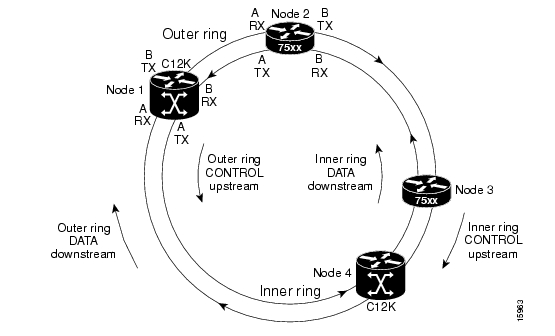
SRP rings are media independent and can operate over a variety of underlying technologies, including SONET/SDH, wavelength division multiplexing (WDM), and dark fiber. This ability to run SRP rings over any embedded fiber transport infrastructure provides a path to packet-optimized transport for high- bandwidth IP networks. Figure 1 shows an SRP ring created with OC-12c/STM-4c DPT line cards installed in a Cisco 12000 Series Internet Router and a Cisco 7500 series Router.
Figure 1 SRP Ring Example
To distinguish between the two rings, one is referred to as the "inner" ring and the other as the "outer" ring. SRP operates by sending data packets in one direction (downstream) and sending the corresponding control packets in the opposite direction (upstream) on the other fiber. This allows SRP to use both fibers concurrently to maximize bandwidth for packet transport and to accelerate control signal propagation for adaptive bandwidth utilization and for self-healing purposes.
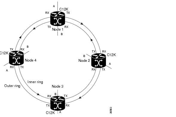
As shown in Figure 1, an SRP node uses SRP side A to receive (RX) outer ring data and transmit (TX) inner ring data. The node uses SRP side B to receive (RX) inner ring data and transmit (TX) outer ring data. Side A on one node connects to Side B on an adjacent SRP node.
Feature Benefits
•
•
•
•
•
•
•
•
•
•
Related Features and Technologies
The Single Ring Recovery (SRR) protocol, an extension that offers additional features to SRP, is also available. For information about how to configure and use the SRR protocol, refer to the Single Ring Recovery Protocol publication at http://www.cisco.com/univercd/cc/td/doc/product/software/ios120/120newft/120limit/120s/120s16/srr.h tm.
Related Publications
The following is a list of publications that relate to the SRP feature:
•
This web site provides access to the Installation and Configuration guides used with Cisco 7200 Series Internet Routers.
•
This document describes the initial hardware installation and procedures for performing the basic system configuration of a Cisco 7500 series router.
•
This web site provides access to the Installation and Configuration guides used with Cisco 7600 Series Internet Routers.
•
This web site provides access to the Software Configuration guides used with Cisco 7600 Series Internet Routers.
•
This guide provides hardware installation and basic configuration procedures for the Cisco 10720 Internet Router.
•
This guide provides hardware installation and basic configuration procedures for the Cisco 10720 Internet Router.
•
This web site provides access to the Installation and Configuration guides used with Cisco 12000 Series Internet Routers.
•
This document provides hardware installation and configuration notes with instructions for installing, configuring, and troubleshooting Dynamic Packet Transport (DPT) line cards on supported Cisco 12000 Series Internet Routers.
•
This document describes the basic configuration of the Cisco 12000 Series Internet Router and configuration and troubleshooting tasks.
•
This document describes the Single Ring Recovery (SRR) protocol, an extension to the Spatial Reuse Protocol (SRP). The SRR protocol allows Dynamic Packet Transport (DPT) rings to operate over a single fiber.
•
This document describes memory requirements and platform-specific information.
•
–
–
–
–
–
–
–
–
–
–
–
–
–
–
See the "Obtaining Documentation" section for information on how to obtain
Cisco publications.Supported Platforms
DPT line cards are supported on the following router platforms:
•
•
•
•
•
Finding Support Information for Platforms and Cisco IOS Software Images
Use Cisco Feature Navigator to find information about platform support and Cisco IOS software image support. Access Cisco Feature Navigator at http://www.cisco.com/go/fn. You must have an account on Cisco.com. If you do not have an account or have forgotten your username or password, click Cancel at the login dialog box and follow the instructions that appear.
Supported Standards, MIBs, and RFCs
Standards
No new or modified standards are supported by this feature.
MIBs
•
•
To obtain lists of supported MIBs by platform and Cisco IOS release, and to download MIB modules, go to the Cisco MIB website on Cisco.com at http://www.cisco.com/public/sw-center/netmgmt/cmtk/mibs.shtml.
RFCs
•
•
Prerequisites
The SRP feature requires the following on all supported router platforms:
•
•
Note
ip cef command to enable Cisco Express Forwarding (CEF) before you can use a DPT line card.
Configuration Tasks
Configuration tasks for the SRP feature are presented in the following sections. Each task is identified as either optional or required.
•
•
•
•
•
Note
The MAC address on each SRP interface has a relationship with the IP address. Even though (in the examples) all DPT line cards are in slot 2 and port 0 in the routers on the network, you can also identify an SRP interface by its unique IP or MAC address. Sample IP and MAC addresses of routers containing DPT line cards that are used in the following configuration tasks are presented in Table 1.
Caution
Assigning an IP Address
This is a required task. This section explains how to assign an IP address to an SRP interface. Each node on the ring must have an IP address assigned to its SRP interface. To assign an IP address, follow these steps in global configuration mode:
Configuring the Topology-Timer
This is a required task. This section explains how to configure the topology-timer on an SRP ring. The srp topology-timer interface configuration command and a specified value determine how frequently topology discovery messages are sent around the ring to identify the current nodes on the SRP ring. Topology discovery is always on. The topology discovery frequency is user configurable. The default value is 5 seconds. To configure the topology-timer, enter the following commands, starting in privileged EXEC mode
:
Note
Configuring SRP Priority-Map Transmit
This is an optional task. This section explains how to configure the minimum SRP priority value that an IP packet must have in order to be queued in the high-priority transmit and transit queues on an SRP interface. IP packets with SRP priority values below the configured value are queued in the low-priority transmit and transit queues.
Note
Use the srp priority-map transmit <min-srp-pri-value> interface configuration command, where min-srp-pri-value specifies the minimum SRP priority value (in the range of 1 to 7) for packets to be sent to the high-priority queues. To specify that all packets are sent to the low-priority transmit and transit queues, enter 8 for <min-srp-pri-value>.
To configure the SRP priority-map, enter the following commands, starting in privileged EXEC mode:
Note
Configuring SRP Rate-Limit
This is a required task. This section explains how to configure the amount of high- and low-priority traffic being transmitted from the router onto the SRP ring, by using the srp tx-traffic-rate interface configuration command. To configure the SRP rate-limit, enter the following commands, starting in privileged EXEC mode:
Configuring SRP Layer 3 Fast Notification
This is an optional task. Starting in IOS Release 12.0(27)S, the SRP - Layer 3 Fast Notification feature is supported on Cisco 12000 series Internet Routers and on the Cisco 10720 Internet Router. This feature allows for faster convergence of Layer 3 routing protocols in case of SRP ring events that cause nodes to be dropped from the ring's topology and is enabled by default.
With the Layer 3 Fast Notification feature, changes in a ring's topology map are reported immediately to Layer 3 protocols. The Layer 3 hello and routing update timers are bypassed, resulting in Layer 3 sub-second convergence.
Note
When the Single Ring Recovery (SRR) protocol is enabled, faster convergence of Layer 3 routing protocols does not occur. The SRR protocol enables an SRP ring to preserve full node connectivity in the event of multiple failures on one of its two counter-rotating rings while the other is failure free. In all other cases, the SRP ring maintains the standard SRP intelligent protection switching (IPS) behavior.To configure SRP Layer 3 notification, enter the following commands, starting in privileged EXEC mode:
Rejecting Packets from a Specific Source Address
This is an optional task. By default, an SRP interface accepts packets from any source. You can configure an SRP interface to reject all packets from a specific source MAC address. This may be useful if there are nodes on the ring that should not communicate.
To configure an SRP interface to reject all packets from a specific source MAC address, enter the following commands, starting in privileged EXEC mode:
SONET/SDH Configuration Parameters
Table 2 lists the default configuration values of the DPT line card. To modify the configuration parameters, enter the following commands, starting in privileged EXEC mode:
Table 2 DPT Line Card Default Configuration Values
Framing
srp framing [sdh | sonet] [a | b]
SONET
SONET overhead
srp flag [c2 value] 0 value] [a | b]
c2 set to 0x16
j0 set to 0xCCClock source1
srp clock-source [internal | line ] [a | b]
—
1 This value varies depending on the DPT line card in use.
To modify SONET/SDH configuration parameters, enter the following commands, starting in privileged EXEC mode:
SRP IPS Command Options
This is an optional task. This section explains how to use SRP IPS command options to enable or override IPS modes on the SRP ring. There are two SRP IPS modes:
•
•
Note
For example, you can enter an srp ips request forced-switch command to force data traffic to one side of the ring when a DPT line card is removed from a router slot, or in response to an event. Table 3 describes the IPS requests in the order of priority, from higher to lower.
If an automatic or user-configured protection switch is requested for a given span, the node that receives the protection request issues a protection request to the node on the other end of the span using both the short path over the failed span, because the failure may be unidirectional, and the long path around the ring.
As the protection requests travel around the ring, the protection hierarchy is applied. For example, if a high-priority Signal Fail (SF) request enters the ring, it overrides a pre-existing lower-priority Signal Degrade (SD) request. If an event or a user-configured command enters a low-priority request, it is not allowed if a high-priority request is present on the ring.
Note
All protection switches are performed bidirectionally and enter wraps at both ends of a span for transmit and receive directions, even if a failure is only unidirectional.
To enter user-configured SRP IPS requests when they are needed, enter the following commands, starting in privileged EXEC mode:
Monitoring and Maintaining the SRP Ring
Use the information in the following sections to monitor and maintain the SRP ring:
•
•
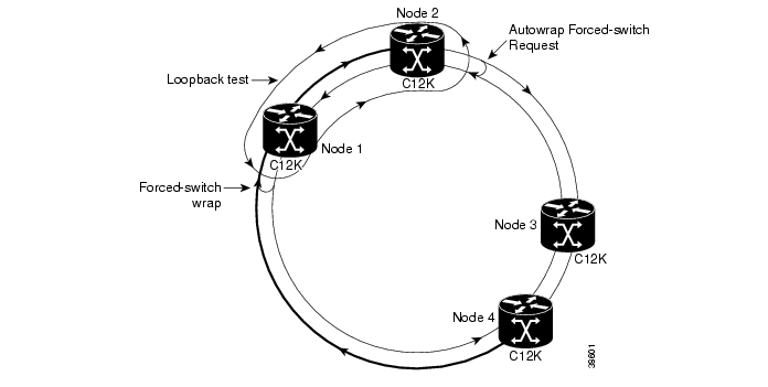
Running Loopback Tests on an SRP Ring
When connectivity is not achieved because of a signal failure or degradation, you can use the srp loopback interface configuration command to test the node-to-node fiber connection. You can also use the srp loopback interface command when fiber or equipment connections are rearranged, or if new connectivity problems arise. Clocking is automatically set when you enter srp loopback mode. Clocking returns to the default when you exit srp loopback mode.
Caution
Note
side A.The following SRP loopback configuration example is for an SRP ring created with an OC-12c/STM-4c DPT line card
The following SRP loopback configuration example is for an SRP ring created with two OC-48c/STM-16c or two OC-192c/STM-64c DPT line cards that use one SRP interface and IP address.
Figure 2 shows an srp loopback line configuration example of an SRP ring.
Figure 2 SRP Ring in Loopback Mode
Using show Commands to Display SRP Ring Configuration
To display information about SRP interfaces on an SRP ring, use the following Cisco IOS software show commands in privileged EXEC mode:
Table 4 explains the terms used in show command output.
DPT Line Card Configuration Examples
This section describes how to configure DPT line cards and contains the following configuration tasks and other information:
•
•
•
•
•
•
Note
Although the card cages of Cisco 12000 Series Internet Routers differ, the designated use of slots and the process of adding and deleting nodes are basically the same for all Cisco 12000 Series
Internet Routers.
Although the procedures in this section refer to Cisco 12000 Series Internet Routers, you can also perform them on Cisco 7200 Series Routers, Cisco 7500 Series Routers, Cisco 7600 Series Routers, and Cisco 10700 Series Internet Routers.Adding a Node to the Ring - Method 1
This section explains how to add Node 5 to a 4-node ring. The examples in this section use OC-12c/STM-4c DPT line cards.
You can insert a new node on a ring without powering down the routers on your network. As long as one connection remains active, data traffic will pass through the fiber from the source node to the destination node, uninterrupted. The new node will be placed between Node 1 and Node 4 on the ring.
The connections between the two existing nodes must be broken to insert the connections to the new node. This intentional break in the ring is handled by Intelligent Protection Switching (IPS).
You can add a node by using one of the following methods:
1.
2.
Note
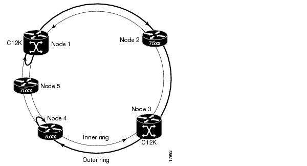
The following examples show how to add a fifth node to a four-node ring. The nodes are named Router1, Router2, and so on. The additional node, Router5, will be added between Router1 and Router4. Side A of Router5 connects to side B of Router4, and side B of Router5 connects to side A of Router1.
The following illustrations use a single DPT line card. Figure 3 and Figure 4 show the physical configuration. Figure 5 and Figure 6 show the logical configuration.
Figure 3 Four Routers on the SRP Ring (Cisco 12008 Internet Router Shown)
Figure 4 Adding a Router to the OC-12c/STM-4c SRP Ring (Cisco 12008 Internet Router Shown)
Figure 5 shows a four-node ring before a fifth node is added.
Note
Figure 5 SRP Ring Topology with Four Nodes
Figure 6 shows a ring with forced-switch wraps entered at Node 1 and Node 4. Node 5 is added to the ring between the forced-switch wraps.
Figure 6 SRP Ring Topology with a Fifth Node Added to a Wrapped Ring
Use the ping command to verify that you can communicate with an SRP interface on the ring.
Step 1
Router1# configure terminal
Router1(config)# interface srp 2/0
Type configure terminal to enter global configuration mode. Specify the new node on the ring by entering interface srp command.
Step 2
Router1(config-if)# ip address 10.1.2.1 255.255.255.0
Enter the IP address of the node.
Step 3
Router1(config-if)# no shutdown
Enter the no shutdown command to enable the SRP interface.
Step 4
Router1# ping 10.1.2.5
Use the ping command in privileged EXEC mode to verify that you can communicate with a new SRP interface on the ring.
Step 5
None
If the ping is successful, continue configuring the new SRP interface. If the ping is unsuccessful, go to the following section, "Adding a Node to the Ring - Method 2."
Adding a Node to the Ring - Method 2
This section shows how to add a fifth node to a four-node ring, using Cisco IOS commands that insert forced-switch wraps away from the area on the fiber where the node is being added, to ensure a minimal loss of data traffic. The examples in this section use OC-12c/STM-4c DPT line cards.
For the purpose of this example, Node 5 will be placed between Node 1 and Node 4. Figure 3 and Figure 4 show the physical configuration. Figure 5 and Figure 6 show the logical configuration.
To add a node to a ring, follow the configuration example in this section, enter the following commands, starting in privileged EXEC mode.
Step 1
Router1# configure terminal
Type configure terminal to enter global configuration mode.
Step 2
Router1(config)# interface srp 2/0
Specify the Node 1 SRP interface by entering the interface srp command.
Step 3
Router1(config-if)# srp ips request forced-switch a
Stop data traffic flowing from Node 1 on the fiber that will be disconnected by entering an srp ips request forced-switch command to create a wrap next to Node 1 on side A.
Step 4
Router1(config-if)# end
Type end to return to global configuration mode.
Step 5
None
Disconnect the fiber-optic cables connecting
Node 1 to Node 4.Step 6
None
Connect the cables to add the new node while observing the receive (RX) and transmit (TX) cabling relationship.
Step 7
Router1(config)# interface srp 2/0
Specify the Node 1 SRP interface by entering the interface srp command.
Step 8
Router1(config-if)# no srp ips request forced-switch a
Remove the wrap on Node 1 by entering the no srp ips request forced-switch command.
Step 9
Router1(config-if)# end
Type end to return to privileged EXEC mode.
Step 10
Router1# show srp topology
Use the show srp topology command to confirm that the wraps have disappeared and the new node is part of the ring topology. (See Figure 6.)
It takes a few seconds for the new ring topology to become known, so you may have to retry the command a few times.
Deleting a Node from the Ring - Method 1
This section explains how to delete Node 5 that is positioned between Node 1 and Node 4 on the ring. The examples in this section use OC-12c/STM-4c DPT line cards. You must disconnect the cables to break the connection between Node 5 and Nodes 1 and 4. After Node 5 is removed, you must connect Node 1 and Node 4. The intentional break on the ring is handled by the IPS facilities.
There are two ways to delete a node:
•
•
Note
The following configuration example shows how to remove a node from a five-node ring. The nodes are named Router1, Router2, and so on. The Router5 node will be removed from its current position between Router1 and Router4. Then side A of Router1 connects to side B of Router4.
To remove a node from a ring, follow the configuration example in this section, starting in privileged EXEC mode.
Step 1
Step 2
Step 3
Step 4
Step 5
Step 6
Deleting a Node from the Ring - Method 2
The following configuration example shows how to remove a node from a ring using forced protection switches to insert wraps on the ring, thereby logically removing the node from the ring prior to physically removing it. The examples in this section use OC-12c/STM-4c DPT line cards.
As in the previous example, you will remove Router5 from its current position between Router1 and Router4. To remove a node from a ring, follow the configuration example in this section, starting in privileged EXEC mode.
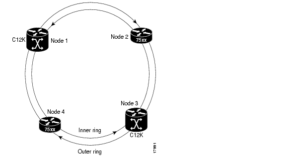
SRP Rings with Mated DPT Line Cards
The OC-48c/STM-16c and OC-192c/STM-64c DPT line cards have a front panel D-type connector. This connector is used to connect a copper coaxial cable that mates two of the same line cards. The copper coaxial cable is referred to as a mate cable.
When you install two line cards that are connected by a mate cable, they create a two-fiber SRP ring with side A and side B. Both line cards are administratively down by default. You must use the hw-module slot number srp command to enable the paired line cards as one SRP interface with one IP address. Side A is automatically the far left (or top if horizontally installed) slot of the pair of line cards. For example, if the line cards are installed in slots 4 and 5, you would enter hw-module slot 4 srp.
The mate cable facilitates front panel interconnection for pass-through traffic between these line cards.
•
•
•
Note
Figure 7 shows synchronized and unsynchronized conditions when the mate cable is attached to two 1OC-48c/STM-16c DPT line cards.
Figure 7 Two DPT Line Cards with a Mate Cable (OC-48c/STM-16c DPT Line Cards Shown)
When the two line cards are not connected by the mate cable, the RX and TX fiber is terminated for either the side A or side B direction of the ring, depending on which line card was removed. The IP address and MAC address remain the same on a single-fiber SRP ring.
Figure 8 shows a single-fiber SRP ring with a wrap at each end to pass-through traffic and ensure that all data packets will reach their destination. The Wrap LED on the single (left- or top-most) OC-48c/STM-16c DPT line card remains on until the mate cable is reattached to a pair of line cards. The right OC-48c/STM-16c DPT line card becomes idle.
Figure 8 Two Unconnected DPT Line Cards and a Single-fiber SRP Ring with Wraps on Each End
(OC-48c/STM-16c DPT Line Cards Shown)
Note
On an SRP ring created by two OC-48c/STM-16c or OC-192c/STM-64c DPT line cards, a Cisco 12000 Series Internet Router collects data and passes it to another Cisco 12000 Series Internet Router. On the SRP ring, Cisco 12000 Series Internet Routers aggregate traffic toward other Cisco 12000 Series Internet Routers.
Note
Each time you install two line cards that are connected by a mate cable in a Cisco 12000 Series Internet Router, it appears on the ring as a node with an SRP interface. Each SRP ring is composed of nodes that are interconnected by two fiber rings, which are designated as inner and outer. Traffic flows clockwise on the outer ring and counterclockwise on the inner ring. Side A has outer-ring receive fiber, and side B has inner-ring receive fiber. (See Figure 9.)
Figure 9 SRP Ring
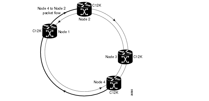
In a normal state, data packets flow from Node 4 to Node 2 by taking the short single-hop path shown in Figure 10.
Figure 10 SRP Ring in a Normal State
In response to a fiber cut between Node 1 and Node 2, wraps are inserted that direct traffic away from the fiber cut. Wrap mode is initiated when a node or fiber failure occurs on the ring between Node 1 and Node 2. The Wrap LED is active.
Figure 11 shows how IPS allows the ring to recover automatically from node or fiber failures by wrapping away from the failures and routing traffic around the wraps. The nodes adjacent to the failure will wrap the ring onto the alternate fiber. The data packets will take the multihop path from Node 4 to Node 2.
Figure 11 SRP Ring with a Fiber-Cut in Wrap Mode
Configuring Mated DPT Line Cards
When you first install a pair of OC-48c/STM-16c or OC-192c/STM-64c DPT line cards, always ensure that the first line card is inserted into the lowest slot number first. For example, if a pair of 1OC-48c/STM-16c DPT line cards are present in Cisco 12000 Series Internet Router slots 2 and 3, the line card in slot 2 is the first card of the pair (side A) and the line card in slot 3 is the second card (side B).
At installation, the two line cards that are connected by a mate cable are administratively down. The following procedures describe how to use the hw-module slot number srp command in privileged EXEC mode to enable the paired line cards as one interface with one IP address. Side A is automatically the left- or top-most slot of the pair of line cards.
Note
Before you remove both line cards, Cisco recommends that you use the shutdown command to disable the SRP interface to prevent anomalies when you reinstall two new or reconfigured line cards. When you shut down an SRP interface, it is designated as administratively down in the show command display.Creating a Ring with Two DPT Line Cards
This section provides procedures on how to create an SRP ring using two line cards that are connected with a mate cable and are installed in a Cisco 12000 Series Internet Router. Follow these steps to create a four-node SRP ring and use Figure 12 and Figure 13 as references.
Note
Step 1
Step 2
The labels under the fiber connectors identify side A, TX and RX, and side B, TX and RX. Use Figure 12, Figure 13, and Table 5 to create cable connections for a four-node ring with two line cards.
Figure 12 Creating an SRP Ring Using Two DPT Line Cards (OC-48c/STM-16c Shown)
Figure 13 4-Node SRP Ring
Table 5 lists the cable connections for a 4-node ring.
Creating a Metropolitan-Area Network with SRP Rings
In this example, an OC-48c/STM-16c SRP ring is used to interconnect two OC-12c/STM-4c access rings to form a larger hierarchical SRP ring topology by directly connecting two Cisco 12000 Series Internet Routers together using direct fiber connections without the use of SONET Add/Drop Multiplexers (ADMs). (See Figure 14.)
Note
Figure 14 Two OC12 SRP Rings Connected to an OC48 SRP Ring
The following configuration example shows the Cisco IOS commands used to configure SRP rings on the GSR+ A and GSR+ B routers in Figure 14.
GSR+ A Configuration
GSR+A:Building configuration...Current configuration:!version 12.0no service padservice timestamps debug uptimeservice timestamps log uptimeservice password-encryption!hostname GSR+A!!hw-module slot 4 srp!ip subnet-zerono ip domain-lookupip multicast-routing distributedip pim rp-address 10.8.1.20 1!interface Loopback0ip address 10.0.0.1 255.255.255.252no ip directed-broadcast!interface SRP1/0ip address 10.10.10.1 255.255.255.192no ip redirectsno ip directed-broadcastip pim sparse-modeip mroute-cache distributedload-interval 30!interface Ethernet0ip address 10.100.1.2 255.255.255.0no ip directed-broadcastno ip route-cache cef!interface SRP4/0ip address 10.10.20.1 255.255.255.192no ip redirectsno ip directed-broadcastip pim sparse-modeip mroute-cache distributedload-interval 30srp topology-timer 1srp ips wtr-timer 10!router ospf 100network 10.10.10.0 0.0.0.255 area 1network 10.10.20.0 0.0.0.255 area 0network 10.0.0.1 0.0.0.0 area 0auto-cost reference-bandwidth 2488!ip classless!GSR B Configuration
GSR+B:Building configuration...Current configuration:!version 12.0no service padservice timestamps debug uptimeservice timestamps log uptimeservice password-encryption!hostname GSR+B!!hw-module slot 4 srp!ip subnet-zerono ip domain-lookupip multicast-routing distributedip pim rp-address 10.8.1.20 1!interface Loopback0ip address 10.0.0.2 255.255.255.252no ip directed-broadcast!interface SRP1/0ip address 10.10.30.1 255.255.255.192no ip redirectsno ip directed-broadcastip pim sparse-modeip mroute-cache distributedload-interval 30!interface Ethernet0ip address 10.100.1.5 255.255.255.0no ip directed-broadcastno ip route-cache cef!interface SRP4/0ip address 10.10.20.2 255.255.255.192no ip redirectsno ip directed-broadcastip pim sparse-modeip mroute-cache distributedload-interval 30srp topology-timer 1srp ips wtr-timer 10!router ospf 100network 10.10.30.0 0.0.0.255 area 2network 10.10.20.0 0.0.0.255 area 0network 10.0.0.2 0.0.0.0 area 0auto-cost reference-bandwidth 2488!ip classlessVerifying SRP Connections
Use the show controllers srp command and look at the path trace information (if no other path- terminating equipment exists). An alarm message is generated if a connection occurs on port A
(- port A) or port B (- port B).Troubleshooting Tips
•
–
If the dBm levels are higher than the specification (not enough power), clean all optics and reduce the number of fiber splices or connections (for example, a fiber patch panel). Verify the integrity of the fiber used (no kinks, breaks, or tight coils or bends). If dBm levels are still too high, change to a more powerful optic at the transmission side.–
–
–
side A cards one way and all side B cards the opposite way.–
•
–
–
Caution
Command Reference
This section documents only new or modified commands used to configure the Spatial Reuse Protocol on supported DPT line cards.
•
•
•
•
•
For information about the debug commands used to troubleshoot an SRP ring, see debug Commands.
Note
The OC-12c/STM-4c DPT line card commands specify side A or side B. The OC-48c/STM-16c and OC-192c/STM-64c DPT line card commands do not specify a side.
The OC-48c/STM-16c DPT line card command reference immediately follows the OC-12c/STM-4c DPT line card command reference.clear counters srp
To clear the output from the show srp and show srp source-counters or show srp counters commands, use the clear counters srp slot/port command in privileged EXEC mode.
clear counters srp slot/port
Syntax Description
Defaults
If no interface is specified by a slot/port combination, counters for all SRP interfaces on the router are cleared.
Command Modes
Privileged EXEC
Command History
Usage Guidelines
This command applies to SRP interfaces only.
Examples
The following example shows how to use the clear counters srp command to make the counts displayed from the show srp source-counters command return to zero:
Router# show srp source-countersSource Address Information for Interface SRP2/00000.0000.0009, index 1, pkt. count 00000.0000.0010, index 2, pkt. count 1260000.0000.0011, index 3, pkt. count 0Router# clear counters srp 2/0Clear "show interface" counters on this interface [confirm]yRouter#*Jan 2 20:52:26.621: %CLEAR-5-COUNTERS: Clear counter on interface SRP2/0Related Commands
show controllers srp
To display the currently running SRP controller, use the show controllers srp slot/port command in privileged EXEC mode.
show controllers srp [slot/port] [details] [transceiver]
Syntax Description
Defaults
No default behavior or values.
Command Modes
Privileged EXEC
Command History
Usage Guidelines
This command applies to SRP interfaces only.
Starting in IOS Release 12.0(30)S, you can enter the show controllers srp slot/port transceiver command to display additional information on the status of the small form-factor pluggable (SFP) module used in an SRP port.
Examples
This example shows the output of the show controllers srp command for a specified SRP interface.
Note that for a 4-Port OC-12c/STM-4c DPT ISE, 4-Port OC-48c/STM-16c DPT, or 1-Port OC-192c/STM-64c DPT line card, the optical power usage is displayed at the bottom, following the SRP controller configuration:
Router1# show controllers srp 3/0SRP3/0 - Side A (Outer RX, Inner TX)SECTIONLOF = 1 LOS = 1 BIP(B1) = 0LINEAIS = 1 RDI = 0 FEBE = 0 BIP(B2) = 0PATHAIS = 1 RDI = 0 FEBE = 0 BIP(B3) = 0LOP = 0 NEWPTR = 0 PSE = 0 NSE = 0Active Defects: SLOF SLOS LAIS PAISActive Alarms: SLOSAlarm reporting enabled for: SLOS SLOF PLOPFraming : SONETRx SONET/SDH bytes: (K1/K2) = 0/0 S1S0 = 0 C2 = 0Tx SONET/SDH bytes: (K1/K2) = 0/0 S1S0 = 0 C2 = 0x16 J0 = 0x1Clock source : InternalFramer loopback : NonePath trace buffer : UnstableBER thresholds: SF = 10e-3 SD = 10e-6IPS BER thresholds(B3): SF = 10e-3 SD = 10e-6TCA thresholds: B1 = 10e-6 B2 = 10e-6 B3 = 10e-6--More--Optical Power MonitoringRx optical power: -31 (+/- 2)dBmTx optical power: -13 (+/- 2)dBmSRP3/0 - Side B (Inner RX, Outer TX)SECTIONLOF = 1 LOS = 1 BIP(B1) = 0LINEAIS = 1 RDI = 0 FEBE = 0 BIP(B2) = 0PATHAIS = 1 RDI = 0 FEBE = 0 BIP(B3) = 0LOP = 0 NEWPTR = 0 PSE = 0 NSE = 0Active Defects: SLOF SLOS LAIS PAISActive Alarms: SLOSAlarm reporting enabled for: SLOS SLOF PLOPFraming : SONETRx SONET/SDH bytes: (K1/K2) = 0/0 S1S0 = 0 C2 = 0Tx SONET/SDH bytes: (K1/K2) = 0/0 S1S0 = 0 C2 = 0x16 J0 = 0x1Clock source : InternalFramer loopback : NonePath trace buffer : UnstableBER thresholds: SF = 10e-3 SD = 10e-6IPS BER thresholds(B3): SF = 10e-3 SD = 10e-6TCA thresholds: B1 = 10e-6 B2 = 10e-6 B3 = 10e-6Optical Power MonitoringRx optical power: -31 (+/- 2)dBmTx optical power: -12 (+/- 2)dBmThe following example shows the output for the show controllers srp transceiver command when it is used to check the status of the SFP module used in an SRP port on a Dual Mode IEEE 802.17 RPR/SRP uplink card.
Router# show controllers srp 1/1 transceiverShow Transceiver: Side AStatic informationID: SFP transceiverExtended ID: 4Connector: LCSONET compliance: OC48SRGigabit Ethernet compliance: unspecifiedFibre Channel link length: unspecifiedFibre Channel transmitter technology: unspecifiedFibre Channel transmission media: unspecifiedFibre Channel speed: unspecifiedEncoding: reservedBit Rate: 2500 MbpsSingle mode fiber supported length: 2 kmUpper bit rate limit: unspecifiedLower bit rate limit: unspecifiedDate code (yyyy/mm/dd): 2004/04/21Vendor PN: SCP6828-C5-BNEVendor revision number: DVendor serial number: ECL0817001LTransceiver status informationDiagnostics calibration is externalTemperature 39 (+/-3 Celsius)Voltage in transceiver 3231000 uV (+/- 10 mV)TX bias 8940 uA (+/- 100uA)TX power 320200 nW / -4 dBm (+/- 3dBm)RX power 300300 nW / -5 dBm (+/- 3dBm)No Active AlarmsNo Active WarningsAlarm Thresholds:high lowTemperature 96 C -44 CVoltage 4000000 uV 0 uVTX bias 70000 uA 0 uATX power 1000000 nW / 0 dBm 50100 nW / -13 dBmRX power 1008300 nW / 0 dBm unspecifiedWarning Thresholds:high lowTemperature 91 C - 9 CVoltage 3600000 uV 3000000 uVTX bias 60000 uA 0 uATX power 630900 nW / -2 dBm 79400 nW / -11 dBmRX power 1008300 nW / 0 dBm unspecifiedShow Transceiver: Side BStatic informationID: SFP transceiverExtended ID: 4Connector: LCSONET compliance: OC48SRGigabit Ethernet compliance: unspecifiedFibre Channel link length: unspecifiedFibre Channel transmitter technology: unspecifiedFibre Channel transmission media: unspecifiedFibre Channel speed: unspecifiedEncoding: reservedBit Rate: 2500 MbpsSingle mode fiber supported length: 2 kmUpper bit rate limit: unspecifiedLower bit rate limit: unspecifiedDate code (yyyy/mm/dd): 2004/04/21Vendor PN: SCP6828-C5-BNEVendor revision number: DVendor serial number: ECL0817001MTransceiver status informationDiagnostics calibration is externalTemperature 39 (+/-3 Celsius)Voltage in transceiver 3230200 uV (+/- 10 mV)TX bias 8740 uA (+/- 100uA)TX power 287400 nW / -5 dBm (+/- 3dBm)RX power 310200 nW / -5 dBm (+/- 3dBm)No Active AlarmsNo Active WarningsAlarm Thresholds:high lowTemperature 96 C -44 CVoltage 4000000 uV 0 uVTX bias 70000 uA 0 uATX power 1000000 nW / 0 dBm 50100 nW / -13 dBmRX power 1008300 nW / 0 dBm unspecifiedWarning Thresholds:high lowTemperature 91 C - 9 CVoltage 3600000 uV 3000000 uVTX bias 60000 uA 0 uATX power 630900 nW / -2 dBm 79400 nW / -11 dBmRX power 1008300 nW / 0 dBm unspecifiedRelated Commands
show interfaces srp
To show information about an SRP interface, use the show interfaces srp slot/port command in privileged EXEC mode.
show interfaces srp slot-port [accounting | crb | fair-queue | irb | mac-accounting | precedence | random-detect | rate-limit | shape]
Syntax Descriptions
Defaults
No default behavior or values.
Command Modes
Privileged EXEC
Command History
Usage Guidelines
All of the options are not relevant to SRP interfaces.
Examples
The following example shows how to examine a specific SRP interface using the show interfaces srp slot/port command:
Router# show interfaces srp 2/0SRP2/0 is up, line protocol is upHardware is SRP over SONET, address is 0012.3456.0001 (bia 0008.200e.5954)Internet address is 1.1.1.1/24MTU 4470 bytes, BW 2488000 Kbit, DLY 100 usec, rely 255/255, load 1/255Encapsulation SRP2,Side A: loopback not setSide B: loopback not set3 nodes on the ring MAC passthrough not setSide A: not wrapped IPS local: IDLE IPS remote: IDLESide B: not wrapped IPS local: IDLE IPS remote: IDLELast input 00:00:01, output 00:00:00, output hang neverLast clearing of "show interface" counters 00:00:20Queueing strategy: fifoOutput queue 0/40, 0 drops; input queue 0/75, 0 dropsSide A: 5 minutes output rate 0 bits/sec, 0 packets/sec5 minutes input rate 0 bits/sec, 0 packets/secSide B: 5 minutes output rate 0 bits/sec, 0 packets/sec5 minutes input rate 0 bits/sec, 0 packets/sec0 packets input, 0 bytes, 0 no bufferReceived 0 broadcasts, 0 runts, 0 giants, 0 throttles0 input errors, 0 CRC, 0 frame, 0 overrun, 0 ignored, 0 abort0 packets output, 0 bytes, 0 underruns0 output errors, 0 collisions, 0 interface resets0 output buffer failures, 0 output buffers swapped outSide A received errors:0 input errors, 0 CRC, 0 ignored,0 framer runts, 0 framer giants, 0 framer aborts,0 mac runts, 0 mac giants, 0 mac abortsSide B received errors:0 input errors, 0 CRC, 0 ignored,0 framer runts, 0 framer giants, 0 framer aborts,0 mac runts, 0 mac giants, 0 mac abortsTable 6 describes selected fields from the show interfaces srp command output.
Related Commands
Displays information about SRP interfaces on the ring, including MAC addresses of neighboring nodes, IPS status, source-counters, and topology map.
show srp
To show the current Intelligent Protocol Switching (IPS), source-counter, and topology status of SRP interfaces on the ring, use the show srp slot/port command in privileged EXEC mode.
show srp [srp slot port]
Syntax Description
srp slot/port
(Optional) Identifies the router slot and port number for a specific SRP interface; otherwise, SRP information for all interfaces is shown.
Defaults
No default behavior or values.
Command Modes
Privileged EXEC
Command History
Examples
The following example produces output that displays the IPS, source-counter, and topology status of the SRP interface by using the show srp slot/port command:
Router# show srp 2/0IPS Information for Interface SRP2/0MAC AddressesSide A (Outer ring RX) neighbor 0012.3456.0004Side B (Inner ring RX) neighbor 0012.3456.0002Node MAC address 0012.3456.0001IPS StateSide A not wrappedSide B not wrappedSide A (Inner ring TX) IPS pkt. sent every 1 sec. (next pkt. after 0 sec.)Side B (Outer ring TX) IPS pkt. sent every 1 sec. (next pkt. after 0 sec.)IPS WTR period is 60 sec. (timer is inactive)Node IPS State IDLEIPS Self Detected Requests IPS Remote RequestsSide A IDLE Side A IDLESide B IDLE Side B IDLEIPS messages receivedSide A (Outer ring RX) {0012.3456.0002,IDLE,S}, TTL 128Side B (Inner ring RX) {0012.3456.0004,IDLE,S}, TTL 128IPS messages transmittedSide A (Inner ring TX) {0012.3456.0001,IDLE,S}, TTL 128Side B (Outer ring TX) {0012.3456.0001,IDLE,S}, TTL 128Source Address Information for Interface SRP2/00012.3456.0001, index 1, pkt. count 4098470012.3456.0002, index 2, pkt. count 24793300012.3456.0003, index 3, pkt. count 7243840012.3456.0004, index 4, pkt. count 1472439Topology Map for Interface SRP2/0Topology pkt. sent every 10 sec. (next pkt. after 5 sec.)Last received topology pkt. 00:00:04Nodes on the ring:4Hops (outer ring) MAC IP Address Wrapped Name0 0012.3456.0001 10.1.2.1 No Router11 0012.3456.0002 10.1.2.2 No Router22 0012.3456.0003 10.1.2.3 No Router33 0012.3456.0004 10.1.2.4 No Router4Router#Table 7 describes selected fields from the show srp command output.
Related Commands
show srp counters
To display counters for the packets received, transmitted, and transited on both sides of an SRP node, use the show srp counters srp slot/port command in privileged EXEC mode. The command output displays a subset of the information displayed by the show srp command.
show srp counters [srp slot/port]
Syntax Description
srp slot/port
(Optional) Specifies the router slot and port number of a specific SRP interface; otherwise, the command displays information about all SRP interfaces in the router.
Defaults
No default behavior or values.
Command Modes
Privileged EXEC
Command History
Usage Guidelines
To clear the counters, use the clear counters srp command.
This command applies to SRP interfaces only and reports the per-side counters and rates for various packet paths.
Examples
The following example shows the output from the show srp counters command:
Router# show srp countersData Traffic Counters for Interface SRP2/0Side A:Transit Packets BytesTotal Low Priority: 0 0Total High Priority: 0 0Total Multicast: 0 0Total Unicast: 0 0Host Receive Packets BytesUnicast Low Priority: 0 0Unicast High Priority: 0 0Multicast Low Priority: 0 0Multicast High Priority: 0 0Total Receive Packets BytesUnicast Low Priority: 0 0Unicast High Priority: 0 0Multicast Low Priority: 0 0Multicast High Priority: 0 0Host Transmit Packets BytesUnicast Low Priority: 0 0Unicast High Priority: 0 0Multicast Low Priority: 0 0Multicast High Priority: 0 0Total Transmit Packets BytesUnicast Low Priority: 0 0Unicast High Priority: 0 0Multicast Low Priority: 0 0Multicast High Priority: 0 0Traffic Rate (5 Minutes) packets/sec bits/secTransit Low Priority 0 0Transit High Priority 0 0Transit Multicast 0 0Transit Unicast 0 0Host Receive 0 0Total Receive 0 0Host Transmit 0 0Total Transmit 0 0Received Errors:0 input errors, 0 CRC, 0 ignored,0 framer runts, 0 framer giants, 0 framer aborts,0 mac runts, 0 mac giants, 0 mac ttl stripsSide B:Transit Packets BytesTotal Low Priority: 0 0Total High Priority: 0 0Total Multicast: 0 0Total Unicast: 0 0Host Receive Packets BytesUnicast Low Priority: 0 0Unicast High Priority: 0 0Multicast Low Priority: 0 0Multicast High Priority: 0 0Total Receive Packets BytesUnicast Low Priority: 0 0Unicast High Priority: 0 0Multicast Low Priority: 2 0Multicast High Priority: 0 0Host Transmit Packets BytesUnicast Low Priority: 0 0Unicast High Priority: 0 0Multicast Low Priority: 0 0Multicast High Priority: 0 0Total Transmit Packets BytesUnicast Low Priority: 0 0Unicast High Priority: 0 0Multicast Low Priority: 0 0Multicast High Priority: 0 0Traffic Rate (5 Minutes) packets/sec bits/secTransit Low Priority 0 0Transit High Priority 0 0Transit Multicast 0 0Transit Unicast 0 0Host Receive 0 0Total Receive 0 0Host Transmit 0 0Total Transmit 0 0Received Errors:0 input errors, 0 CRC, 0 ignored,0 framer runts, 0 framer giants, 0 framer aborts,0 mac runts, 0 mac giants, 0 mac ttl stripsTable 8 describes selected fields from the show srp counters command output.
Related Commands
show srp failures
To display all SRP failures that were detected by the router, use the show srp failures srp slot/port command in privileged EXEC mode.
show srp failures [srp slot/port]
Syntax Description
srp slot/port
(Optional) Specifies the router slot and port number of a specific SRP interface; otherwise, the command displays information about all SRP interfaces in the router.
Defaults
None.
Command Modes
Privileged EXEC
Command History
12.0(21)SP
This command was first introduced in Cisco 10720 Internet Routers.
12.0(22)S
This command was first introduced in Cisco 12000 Series Internet Routers.
Usage Guidelines
This command applies to SRP interfaces only and reports the SRP failures that were detected by the router.
Use the show srp failures command when an SRP interface is wrapped and you want to display information about the cause of the failure. This command displays more detailed information than the show srp command.
Examples
The following example shows how to display the self-detected failures in the SRP interface configured on slot 1 port 1.
Router# show srp failures 1/1Self Detected Failures Information for Interface SRP1/1Side A:Reported Debounced Current Stable Debouncestate state state for(sec) delay(sec)HW missing IDLE IDLE IDLE 35909 0Layer 1 IDLE IDLE IDLE 35885 0MAC Keepalive IDLE IDLE IDLE 35590 10Link quality IDLE IDLE IDLE 35909 0Mate interface IDLE IDLE IDLE 35909 10Side mismatch IDLE IDLE IDLE 35845 5Result Self Detect = IDLESide B:Reported Debounced Current Stable Debouncestate state state for(sec) delay(sec)HW missing IDLE IDLE IDLE 35910 0Layer 1 IDLE IDLE IDLE 35230 0MAC Keepalive IDLE IDLE IDLE 35239 10Link quality IDLE IDLE IDLE 35910 0Mate interface IDLE IDLE IDLE 35910 10Side mismatch IDLE IDLE IDLE 35241 5Result Self Detect = IDLERouter#Table 9 describes selected fields from the show srp failures command output.
Table 9 show srp failures Command Output Fields
HW missing
The hardware (for example, a line card) is not installed or is still booting up.
Layer 1
No Section Loss of Signal (SLOS), Section Loss of Frame (SLOF), or Line Alarm Indicator Signal (LAIS). For detailed information about a Layer 1 failure, use show controllers srp command.
MAC keepalive
The media access controller (MAC) keepalive timer has expired.
Link quality
The SONET B3 bit error rate (BER) threshold has been crossed. To configure SRP signal degrade detection and signal fail detection, use the srp ips sonet protected command.
Mate interface
The external mate cable on a line card interface is missing or malfunctioning.
Side mismatch
Side A of the node is connected to side A of the neighbor node, or side B of the node is connected to side B of the neighbor node.
Related Commands
show srp ips
To display the Intelligent Protection Switching (IPS) status, use the show srp ips srp slot/port command in privileged EXEC mode. This command displays a subset of the information displayed by the show srp command.
show srp ips [srp slot/port]
Syntax Description
srp slot/port
(Optional) Specifies the router slot and port number of a specific SRP interface; otherwise, the command displays information about all SRP interfaces in the router.
Defaults
SRP IPS is on by default and cannot be disabled.
Command Modes
Privileged EXEC
Command History
Usage Guidelines
This command applies to SRP interfaces only.
Examples
The following example shows how to verify the Intelligent Protection Switching on the ring by using the show srp ips command:
Router# show srp ipsIPS Information for Interface SRP1/1MAC AddressesSide A (Outer ring RX) neighbor 0048.0001.0002Side B (Inner ring RX) neighbor 0048.0001.0001Node MAC address 0001.64fe.fe80IPS StateSide A not wrappedSide B not wrappedSide A (Inner ring TX) IPS pkt. sent every 1 sec. (next pkt. after 1 sec.)Side B (Outer ring TX) IPS pkt. sent every 1 sec. (next pkt. after 1 sec.)inter card bus enabledIPS WTR period is 10 sec. (timer is inactive)Node IPS State: idleIPS Self Detected Requests IPS Remote RequestsSide A IDLE Side A IDLESide B IDLE Side B IDLESide A Failures: noneSide B Failures: noneIPS messages receivedSide A (Outer ring RX) {0048.0001.0002,IDLE,SHORT}, TTL 255Side B (Inner ring RX) {0048.0001.0001,IDLE,SHORT}, TTL 255IPS messages transmittedSide A (Inner ring TX) {0001.64fe.fe80,IDLE,SHORT}, TTL 255Side B (Outer ring TX) {0001.64fe.fe80,IDLE,SHORT}, TTL 255Router#Related Commands
show srp rate-limit
To display the current SRP rate-limit configuration for high- and low-priority traffic, use the show rate-limit srp slot/port command in privileged EXEC mode.
show srp rate-limit srp [slot/port]
Syntax Description
slot/port
(Optional) Specifies the router slot and port number of a specific SRP interface; otherwise, the command displays information about all SRP interfaces in the router.
Defaults
No default behavior or values.
Command Modes
Privileged EXEC
Command History
Usage Guidelines
This command applies to SRP interfaces only.
Examples
The following example shows the output from the show srp rate-limit srp slot/port command.
Router# show srp rate-limit srp 2/0Router#Rate Limit Information for Interface SRP2/0Rate limit of high priority outgoing traffic: 622 MbpsRate limit of low priority outgoing traffic: 1866 MbpsMinimum SRP priority value of high priority outgoing/transit traffic: 5Router#Related Commands
Displays information about SRP interfaces on the ring, including MAC addresses of neighboring nodes, IPS status, source-counters, and topology map.
show srp source-counters
To display the total number of packets received by a node identified by its unique MAC address, use the show srp source-counters srp slot/port command in privileged EXEC mode. The command output displays a subset of the information displayed by the show srp command.
show srp source-counters [srp slot/port]
Syntax Description
srp slot/port
(Optional) Specifies the router slot and port number of a specific SRP interface; otherwise, the command displays information about all SRP interfaces in the router.
Defaults
No default behavior or values.
Command Modes
Privileged EXEC
Command History
Usage Guidelines
To clear the counters, use the clear counters srp command.
The show srp source-counters command is not supported on 10720 Series Internet Routers.
Examples
The following example shows the output from the show srp source-counters command after counting has been switched on for source address 0012.3456.0004:
Router# show srp source-countersSource Address Information for Interface SRP2/00012.3456.0004, index 4, pkt. count 1472439Related Commands
show srp topology
To identify the nodes on the ring, use the show srp topology srp slot/port command in privileged EXEC mode.
show srp topology [srp slot/port]
Syntax Description
srp slot/port
(Optional) Specifies the router slot and port number of a specific SRP interface; otherwise, the command displays information about all SRP interfaces in the router.
Defaults
No default behavior or values.
Command Modes
Privileged EXEC
Command History
Usage Guidelines
This command applies to SRP interfaces only.
Examples
The following example shows the output that identifies SRP interfaces on the ring displayed with the show srp topology command:
Router# show srp topologyTopology Map for Interface SRP2/0Topology pkt. sent every 10 sec. (next pkt. after 5 sec.)Last received topology pkt. 00:00:04Nodes on the ring:4Hops (outer ring) MAC IP Address Wrapped Name0 0012.3456.0001 10.1.2.1 No Router11 0012.3456.0002 10.1.2.2 No Router22 0012.3456.0003 10.1.2.3 No Router33 0012.3456.0004 10.1.2.4 No Router4Related Commands
show srp transit
To display information about traffic buffer delays (minimum, maximum, and average delays) using the time interval specified with the load-interval command, use the show srp transit command in privileged EXEC mode.
show srp transit [srp slot/port]
Syntax Description
Defaults
No default behavior or values.
Command Modes
Privileged EXEC
Command History
Usage Guidelines
Use this command to display the transit buffer delays for high- and low-priority traffic collected using the currently configured load interval.
The transit buffer delay is the number of nanoseconds that it takes for a packet to enter the transit buffer and come back out on the ring. This command allows you to observe the amount of packet latency experienced by traffic on the ring. This information is particularly useful when the ring is congested.
To change the amount of time used to load data and collect delay statistics, use the load-interval command in interface configuration mode.
Examples
The following example shows how to display the buffer transit delays calculated for the SRP interface on port 1 on the line card in slot 1 using a load interval of 5 minutes.
router# show srp transitTransit Buffer Delay Counters for Interface SRP1/1Side A:Transit Delay (5 Minutes) NanosecondsLow TB Min Delay: 700Low TB Avg Delay: 770Low TB Max Delay: 820High TB Min Delay: 0High TB Avg Delay: 0High TB Max Delay: 0Side B:Transit Delay (5 Minutes) NanosecondsLow TB Min Delay: 780Low TB Avg Delay: 790Low TB Max Delay: 820High TB Min Delay: 580High TB Avg Delay: 613High TB Max Delay: 660Related Commands
load-interval
Sets the time (in seconds) used to gather data for computing load statistics.
shutdown
To disable an interface, use the shutdown interface configuration command. To restart a disabled interface, use the no form of this command.
shutdown
no shutdownSyntax Description
This command has no arguments or keywords.
Defaults
Enabled
Command Modes
Interface configuration
Command History
10.0
This command was first introduced.
12.0(6)S
This command invokes the pass-through mode on the SRP ring.
Usage Guidelines
The shutdown command disables all functions on the specified interface. On SRP interfaces, the shutdown command causes the interface to go into pass-through mode, logically removing it from the ring.
This command also marks the SRP interface as unavailable. To verify if an interface is disabled, use the show interface srp slot/port command in privileged EXEC mode. An SRP interface that received the shutdown command is shown as administratively down in the command output.
Examples
The following example disables SRP interface 2/0:
Router(config)# interface srp 2/0Router(config-if)# shutdownRouter(config-if)#The following example enables SRP interface 2/0:
Router(config)# interface srp 2/0Router(config-if)# no shutdownRelated Commands
srp clock-source
To configure the clock source, use the srp clock-source interface configuration command. Use the no form of this command to restore the default srp clock-source.
srp clock-source [line | internal] [a | b]
no srp clock-source [line | internal] [a | b]Syntax Description
Defaults
srp clock-source [line | internal] [a | b]
Command Modes
Interface configuration
Command History
Usage Guidelines
This command applies to SRP interfaces only.
When you configure a connection between two Cisco 10700 Series Internet Routers, you can configure the SRP interfaces for clock source as follows:
•
•
•
Examples
The following is an example of how to use the srp clock-source command to select line as a clock source on side A:
Router# configure terminalRouter(config)# interface srp 2/0Router(config-if)# srp clock-source line aRouter(config-if)#Related Commands
srp fast-convergence
To enable faster Layer 3 convergence in case of an SRP node failure, use the srp fast-convergence interface configuration command. Use the no form of this command to disable Layer 3 fast notification on an SRP interface.
srp fast-convergence
no srp fast-convergenceSyntax Description
This command has no arguments or keywords.
Defaults
Faster convergence of Layer 3 routing protocols in case of node failure is enabled by default.
Command Modes
Interface configuration
Command History
12.0(27)S
This command was first introduced on Cisco 12000 series Internet Routers and on the Cisco 10720 Internet Router.
Usage Guidelines
Starting in IOS Release 12.0(27)S, the SRP - Layer 3 Fast Notification feature is supported on Cisco 12000 series Internet Routers and on the Cisco 10720 Internet Router. This feature enables faster convergence of Layer 3 routing protocols in case of SRP ring events that cause nodes to be dropped from the ring's topology.
The Layer 3 Fast Notification feature is triggered only as a result of a wrap event or a pass-through event, when a change in the SRP ring topology indicates that a node should be dropped from the ring. The Layer 3 Fast Notification feature is not triggered when an SRP node joins the ring.
Note
In IOS Release 12.0(26)S and earlier releases, a node failure in an SRP ring causes ring wrap to occur around the failed node. Traffic flow from other nodes in the ring to the failed node continues, even if there is an alternative path, until the Internal Gateway Protocol (IGP) reconverges. The traffic is interrupted for seconds because the SRP node failure is transparent to Layer 3 protocols and IP convergence takes the normal time based on routing updates.
With the Layer 3 Fast Notification feature, changes in an SRP ring's topology map are reported immediately to Layer 3 protocols. The Layer 3 hello and routing update timers are bypassed, resulting in Layer 3 sub-second convergence.
Note
When the Single Ring Recovery (SRR) protocol is enabled, faster convergence of Layer 3 routing protocols does not occur. The SRR protocol enables an SRP ring to preserve full node connectivity in the event of multiple failures on one of its two counter-rotating rings while the other is failure free. In all other cases, the SRP ring maintains the standard SRP intelligent protection switching (IPS) behavior.Layer 3 routing protocols do not reconverge for every ring protection event, but only as a result of ring protection events that indicate that a node should be dropped from the ring. Although topology packets perform the same function, Layer 3 convergence occurs much slower.
OSPF and ISIS use various timers to control how fast a topology change is sent and propagated across an SRP ring and how fast routing computation is performed when a change in topology is received. It is recommended that you tune the OSPF and ISIS timers in your network according to your network complexity and convergence requirements.
Examples
The following example shows how to enable fast Layer 3 convergence in case of node failure and the immediate notification to Layer 3 OSPF and IS-IS protocols:
Router# configure terminalRouter(config)# interface srp 1/1Router(config-if)# srp fast-convergenceRelated Commands
srp flag
To specify SONET/SDH overhead values for the frame header, use the srp flag interface configuration command. Use the no form of this command to restore the default SRP flag.
srp flag [c2 | j0] value [a | b]
no srp flag [c2 | j0] value [a | b]Syntax Description
Defaults
The default value of the c2 byte is 0x16. The default value of the j0 byte is 0x01.
Command Modes
Interface configuration
Command History
Usage Guidelines
This command applies to SRP interfaces only.
Examples
The following example shows how to use the srp flag command to specify the SONET/SDH overhead values on an SRP interface:
Router# configure terminalRouter(config)# interface srp 2/0Router(config-if)# srp flag j0 0x1Router(config-if)#Related Commands
Specifies framing for the packet header and trailer to ensure synchronization and error control.
srp framing
To specify framing for the packet header and trailer to ensure synchronization and error control, use the srp framing interface configuration command. Use the no form of this command to restore the default value for srp framing.
srp framing [sdh | sonet] [a | b]
no srp framing [a | b]Syntax Description
Defaults
The default framing is SONET with the s1s0 bits set to 0.
Command Modes
Interface configuration
Command History
Usage Guidelines
There are two types of framing: SONET and SDH. SONET is the North American standard, while SDH is the European standard. Like clocking, you can configure framing independently for each side of the node.
The value of the s1s0 bits is fixed according to the framing type you configure with the srp framing command:
•
•
This command applies to SRP interfaces only.
Examples
The following example allows you to set framing to SDH by using the srp framing command:
Router# configure terminalRouter(config)# interface srp 2/0Router(config-if)# srp framing sdhRelated Commands
srp ips request forced-switch
To initiate a forced-switch wrap on a ring, use an srp ips request forced-switch interface configuration command. Use the no form of this command to remove the wrap.
srp ips request forced-switch [a | b]
no srp ips request forced-switch [a | b]Syntax Description
a
The side of a node that has outer ring receive fiber is identified as side A.
b
The side of a node that has inner ring receive fiber is identified as side B.
Defaults
srp ips request forced-switch [a | b]
Command Modes
Interface configuration
Command History
Usage Guidelines
This command applies to SRP interfaces only.
Examples
The following example shows how to insert a forced-switch wrap on side A of the interface by entering the srp ips request forced-switch a command:
Router# configure terminalRouter(config)# interface srp2/0Router(config-if)# srp ips request forced-switch aRouter(config-if)#Related Commands
srp ips request manual-switch
To insert a manual-switch wrap on the ring fiber, use an srp ips request manual-switch interface configuration command. Use the no form of the command to remove the wrap.
srp ips request manual-switch [a | b]
no srp ips request manual-switch [a | b]Syntax Description
a
The side of a node that has outer ring receive fiber is identified as side A.
b
The side of a node that has inner ring receive fiber is identified as side B.
Defaults
srp ips request manual-switch [a | b]
Command Modes
Interface configuration
Command History
Usage Guidelines
This command applies to SRP interfaces only.
Note
Examples
The following example shows how to enter a manual-switch wrap on side B of the interface by using the srp ips request manual-switch b command:
Router# configure terminalRouter(config)# interface srp2/0Router(config-if)# srp ips request manual-switch bRouter(config-if)#Related Commands
srp ips sonet protected
Use the srp ips sonet protected interface configuration command to place a 100-millisecond delay (in L2 keepalive wrapping) when the ring side is connected to a protected add/drop multiplexer (ADM) network. This provides the ADM with enough time to protect itself in case of an L1 failure, without causing an L2 wrap.
srp ips sonet protected [a | b]
no srp ips sonet protected [a | b]Syntax Description
a
The side of a node that has outer ring receive fiber is identified as side A.
b
The side of a node that has inner ring receive fiber is identified as side B.
Defaults
no srp ips sonet protected [a | b]
Command Modes
Interface configuration
Command History
Usage Guidelines
This command applies to SRP interfaces only.
Examples
The following example shows how to set the srp ips sonet protected command:
Router# configure terminalRouter(config)# interface srp 2/0Router(config-if)# srp ips sonet protectedRelated Commands
srp ips sonet threshold
To configure SRP signal degrade detection and signal fail detection, use the srp ips sonet threshold interface configuration command. When detected, an SRP signal degradation will trigger the appropriate IPS protection switch. Use the no form of this command to restore the default value.
srp ips sonet threshold [sd-ber | sf-ber] <3-9> [a | b]
no srp ips sonet threshold [sd-ber | sf-ber] <3-9> [a | b]Syntax Description
Defaults
no srp ips sonet threshold [sd-ber | sf-ber] <3-9> [a | b]
Command Modes
Interface configuration
Command History
Usage Guidelines
This command applies to SRP interfaces only.
Examples
The following example shows how to set the srp ips sonet threshold command to 3 seconds on side A:
Router# configure terminalRouter(config)# interface srp 2/0Router(config-if)# srp ips sonet threshold sd-ber 3 aRouter(config-if)#Related Commands
srp ips timer
To control the frequency of the transmission of ips requests, use the srp ips timer interface configuration command. Use the no form of this command to restore the default value.
srp ips timer <value> [a | b]
no srp ips timer [a | b]Syntax Description
value
1 to 60 seconds.
a
The side of a node that has outer ring receive fiber is identified as side A.
b
The side of a node that has inner ring receive fiber is identified as side B.
Defaults
The default setting of the IPS timer is 1 second.
Command Modes
Interface configuration
Command History
Usage Guidelines
This command applies to SRP interfaces only. If a node (side A or side B) is not specified in the command, the IPS timer value is applied to both sides.
Examples
The following example shows how to set the srp ips timer command to 5 seconds on side A:
Router# configure terminalRouter(config)# interface srp 2/0Router(config-if)# srp ips timer 5 aRouter(config-if)#Related Commands
srp ips wtr-timer
To change the srp ips wait-to-restore timer from its default value, use the srp ips wtr-timer interface configuration command. Use the no form of this command to restore the default value.
srp ips wtr-timer <value>
no srp ips wtr-timerSyntax Description
Defaults
60 seconds
Command Modes
Interface configuration
Command History
Usage Guidelines
When the cause of a wrap is removed, the wrap remains in place for a length of time determined by the SRP wait-to-restore timer. This mechanism prevents oscillations on the SRP ring. It is recommended that you configure the srp ips wrt-timer value to the same setting on all nodes on a ring. This means that if you modify the srp ips wrt-timer value on one node, you must reconfigure all other nodes on the ring with the same wait-to-restore timer setting.
Examples
The following example shows how to use the srp ips wtr-timer command to change the SRP IPS wtr-timer to 10 seconds on SRP interface 2/0:
Router# configure terminalRouter(config)# interface srp 2/0Router(config-if)# srp ips wtr-timer 10Router(config-if)# endRelated Commands
srp loopback
To configure the framer into loopback mode, use the srp loopback interface configuration command. Use the no form of this command to restore the default value.
srp loopback [internal | line] [a | b]
no srp loopback [internal | line] [a | b]Syntax Description
Defaults
No loopbacks in place.
Command Modes
Interface configuration
Command History
Usage Guidelines
Using the srp loopback command breaks connectivity. This command is used mostly during the initial setup of the SONET link (such as a node-to-node fiber connection), or when general connectivity is not clearly and obviously achieved. You can also use the srp loopback command when fiber or equipment connections are rearranged, or if new connectivity problems arise. If a node (side A or side B) is not specified in the command, the loopback value is applied to both sides.
Examples
The following example shows how to enter the srp loopback command on side A:
Router# configure terminalRouter(config)# interface srp 2/0Router(config-if)# srp loopback line aRouter(config-if)#Related Commands
srp priority-map transmit
To configure the minimum SRP priority value that an IP packet must have in order to be queued in the high-priority transmit and transit queues, use the srp priority-map transmit command in interface configuration mode. IP packets with SRP priority values below the configured value are queued in the low-priority transmit and transit queues. Use the no form of this command to remove the configured SRP priority value.
srp priority-map transmit <min-srp-pri-value>
no srp priority-map transmit <min-srp-pri-value>Syntax Description
Note
Defaults
IP packets with minimum SRP priority of 6 are queued in the high-priority transmit and transit queues.
Command Modes
Interface configuration
Command History
Usage Guidelines
Use this command to control which IP packets are queued in the high- and low-priority queues for transmitting traffic to the SRP ring and transiting traffic to adjacent nodes.
Starting in IOS Release 12.0(27)S, you can specify that all IP packets on a supported SRP interface are sent to the low-priority queues by entering 8 for the min-srp-pri-value. This feature is supported only on the following DPT line cards:
•
•
•
•
•
Note
Examples
The following example shows that IP packets with priority values of 5 to 7 will be queued in the high- priority transmit and transit queues on the specified SRP interface. IP packets with priority values of 1 to 4 will be queued in the low-priority transmit and transit queues.
Router# configure terminalRouter(config)# interface srp 2/0Router(config-if)# srp priority-map transmit 5Router(config-if)# endRelated Commands
Displays information about SRP interfaces on the ring, including MAC addresses of neighboring nodes, IPS status, source-counters, and topology map.
srp reject
To force the SRP interface to reject packets sent to it by a specified source MAC address, use the srp reject interface configuration command. Use the no form of this command to restore the default value.
srp reject [H.H.H]
no srp reject [H.H.H]Syntax Description
Defaults
no srp reject [H.H.H]
Command Modes
Interface configuration
Command History
Usage Guidelines
This command applies to SRP interfaces only. If the SRP interface is instructed to reject packets by source address, this will be shown by the show srp and show srp source-counters commands.
Examples
The following example shows how to use the srp reject command to configure an SRP interface to reject any packets from source MAC address 0012.3456.0001:
Router# configure terminalRouter(config)# interface srp 2/0Router(config-if)# srp reject 0012.3456.0001Router(config-if)# endRelated Commands
srp report
To enable reporting of selected alarms, use the srp report interface configuration command. Use the no form of this command to restore the default value.
srp report [b1-tca | b2-tca | b3-tca | lais | lrdi | pais | plop | prdi | sd-ber | sf-ber |
slof | slos] [a | b]
no srp report [b1-tca | b2-tca | b3-tca | lais | lrdi | pais | plop | prdi | sd-ber | sf-ber |
slof | slos] [a | b]Syntax Description
Defaults
Reporting enabled for section loss of signal (SLOS), section loss of frame (SLOF), and path loss of pointer (PLOP) errors.
Command Modes
Interface configuration
Command History
Usage Guidelines
To determine which alarms are reported on the SRP interface, use the show controllers srp command.
Examples
The following example shows how to use the srp report command to enable reports for the SD-BER and LAIS alarms on an SRP interface:
Router# configure terminalRouter(config)# interface srp 2/0Router(config-if)# srp report sd-berRouter(config-if)# srp report laisRouter(config-if)#Related Commands
srp shutdown
To shut down an interface by entering a forced switch, use the srp shutdown interface configuration command. Use the no form of this command to remove the forced-switch wrap near the interface.
srp shutdown [a | b]
no srp shutdown [a | b]Syntax Description
a
The side of a node that has outer ring receive fiber is identified as side A.
b
The side of a node that has inner ring receive fiber is identified as side B.
Defaults
srp shutdown [a | b]
Command Modes
Interface configuration
Command History
Usage Guidelines
This srp shutdown command is an abbreviated form of the srp ips request forced-switch interface configuration command that enters a forced-switch request and inserts a wrap on a ring. Use the no form of this command to remove the wrap on the ring. The long form, srp ips request forced-switch, will appear in the show command output.
Note
Examples
The following example shows how to enter an srp shutdown request on side A of an SRP interface:
Router# configure terminalRouter(config)# interface srp 2/0Router(config-if)# srp shutdown aRouter(config-if)#Related Commands
srp threshold
To set the BER threshold values of the specified alarms for a SRP interface, use the srp threshold interface configuration command. Use the no form of this command to restore the default value.
srp threshold [b1-tca | b2-tca | b3-tca | sd-ber | sf-ber] <3-9> [a | b]
no srp threshold [b1-tca | b2-tca | b3-tca | sd-ber | sf-ber] <3-9> [a | b]Syntax Description
Defaults
The default is 6 (10e-6) for all thresholds except for sf-ber, where the default is 3 (10e-3).
Command Modes
Interface configuration
Command History
Usage Guidelines
This command applies to SRP interfaces only. If a node (side A or side B) is not specified in the command, the threshold value is applied to both sides.
Examples
The following example shows how to set the srp threshold values on side A of an SRP interface:
Router# configure terminalRouter(config)# interface srp 3/0Router(config-if)# srp threshold sd-ber 8 aRouter(config-if)# srp threshold b1_tca 4 aRouter(config-if)# endRouter#Related Commands
Shows current alarm thresholds, along with other information.
Controls reporting of selected alarms.
srp topology-timer
To specify the frequency of the topology timer, use the srp topology-timer interface configuration command. Use the no form of this command to restore the default value.
srp topology-timer <value>
no srp topology-timerSyntax Description
Defaults
The default value for the topology timer is 10 seconds.
Command Modes
Interface configuration
Command History
Usage Guidelines
The srp topology-timer interface configuration command and a specified value determine how frequently topology discovery messages are sent around the ring to identify the current nodes on the SRP ring. It is recommended that you configure the same srp topology-timer value on all nodes on an SRP ring. This means that if you modify the topology timer setting on one node, you must reconfigure all other nodes on the ring with the same topology timer value.
Examples
The following example shows how to set the frequency for how often SRP topology packets are sent around the ring to identify the nodes:
Router# configure terminalRouter(config)# interface srp 2/0Router(config-if)# srp topology-timer 100Router(config-if)#Related Commands
srp TX-traffic-rate
To configure the amount of high- and low-priority traffic being transmitted from the router onto the SRP ring, use the srp TX-traffic-rate interface configuration command. Use the no form of this command to remove the TX traffic rate from the configuration.
srp TX-traffic-rate [high | low] <Mbps>
no srp TX-traffic-rate [high | low] <Mbps>Syntax Description
Mbps
Average rate in Mbps. OC-48 DPT line card values must be in increments of 1 Mbps in the range of 1 to 2488. The range for OC-192 DPT line cards is in the range of 1 to 9952.
Defaults
By default, TX-traffic-rate is disabled on low priority and set to 20 Mbps for high priority.
Command Modes
Interface configuration
Command History
Usage Guidelines
Use this command to control the amount of high- and low-priority traffic a node can transmit onto the SRP ring. This command does not control the amount of transit traffic on the ring; that is controlled by the SRP fairness algorithm.
Note
Examples
The following example limits the rate of high-priority traffic transmitted on the ring to an average rate of 622 Mbps (25 percent line bandwidth), and the low-priority traffic transmitted on the ring to an average rate of 1866 Mbps (75 percent line bandwidth):
Router# configure terminalRouter(config)# interface srp 2/0Router(config-if)# srp rate-limit hi 622Router(config-if)# srp rate-limit low 1866Router(config-if)# endRouter#Related Commands
debug Commands
Use the following debug srp commands if you recognize configuration problems that need debugging, such as loss of packets, cyclic redundancy check (CRC) errors, card resets, alarms, and so on. This section describes the following debug commands:
debug srp fast-convergence
To activate troubleshooting information for fast convergence events (when SRP ring events indicate that nodes should be dropped from the ring's topology), use the debug srp fast-convergence command in privileged EXEC mode.
[no] debug srp fast-convergence
Syntax Description
debug srp fast-convergence
Displays information about SRP ring events and the nodes that may be dropped from a ring's topology.
Defaults
no debug srp fast-convergence
Command Modes
Privileged EXEC
Command History
Usage Guidelines
This command applies to the Layer 3 Fast Notification feature. This feature enables faster convergence of Layer 3 routing protocols in case of SRP ring events that cause nodes to be dropped from the ring's topology.
The Layer 3 Fast Notification feature is triggered only as a result of a wrap event or a pass-through event, when a change in the SRP ring topology indicates that a node should be dropped from the ring. The Layer 3 Fast Notification feature is not triggered when an SRP node joins the ring.
Note
When the Single Ring Recovery (SRR) protocol is enabled, faster convergence of Layer 3 routing protocols does not occur. The SRR protocol enables an SRP ring to preserve full node connectivity in the event of multiple failures on one of its two counter-rotating rings while the other is failure free. In all other cases, the SRP ring maintains the standard SRP intelligent protection switching (IPS) behavior.
Examples
The following example shows how to display information about the SRP ring events that indicate that an SRP node may be dropped from the ring's topology:
Router# debug srp fast-convergenceRouter# 02:25:53: srp_input: Neighbor status packet received02:25:53: mac(0003.0003.0003), neighbor(0001.0001.0001), wrap(No), ringid(1), ips req(0)When you enable debugging for fast convergence events with the debug srp fast-convergence command, the current neighbor map is displayed for the SRP node when you enter the show srp topology command:
Router# show srp topologyHops Node Side-A Side-B Wrapped IPS Ring ID0 aaaa.5555.2222 aaaa.5555.1111 aaaa.5555.3333 No 0 01 aaaa.5555.3333 aaaa.5555.2222 aaaa.5555.1111 No 0 02 aaaa.5555.1111 aaaa.5555.3333 aaaa.5555.2222 No 0 0Related Commands
debug srp ips
To debug an SRP interface on the ring, use the debug srp ips command in privileged EXEC mode.
[no] debug srp ips
Syntax Description
Defaults
no debug srp ips
Command Modes
Privileged EXEC
Command History
Usage Guidelines
This command applies to SRP interfaces only.
Examples
The following example shows how to enter the debug mode to debug an SRP interface:
Router# debug srp ipsRelated Commands
Displays SRP interface protocol errors and error statistics.
Debugs information on a specific SRP packet.
Debugs a specific periodic activity.
Examines ring topology information.
debug srp nodename
To display node name packets by the source MAC address, use the debug srp nodename command in privileged EXEC mode.
[no] debug srp nodename
Syntax Description
Defaults
no debug srp nodename
Command Modes
Privileged EXEC
Command History
Usage Guidelines
This command applies to SRP interfaces only.
Examples
The following example shows how to debug a specific periodic activity on an SRP interface:
Router# debug srp nodenameSRP node name debugging is onRouter#*May 9 08:28:39:srp_process_node_name_packet SRP4/0, len 27, 0048.1100.0002, M2305B*May 9 08:28:39:srp_forward_node_name_packet:SRP4/0, len 27, 0048.1100.0002, M2305B*May 9 08:28:39:srp_glean_node_name:SRP4/0, len 27 src 0048.1100.0002 data M2305B*May 9 08:28:48:srp_process_node_name_packet SRP4/0, len 27, 0048.3300.0001, M2307A*May 9 08:28:48:srp_passthrough_node_name_packet:SRP4/0, len 27, 0048.3300.0001, M2307A*May 9 08:28:48:srp_process_node_name_packet SRP4/0, len 27, 0048.3300.0001, M2307A*May 9 08:28:48:srp_forward_node_name_packet:SRP4/0, len 27, 0048.3300.0001, M2307A*May 9 08:28:48:srp_glean_node_name:SRP4/0, len 27 src 0048.3300.0001 data M2307ARelated Commands
debug srp packet
To display information about how to debug a specific SRP packet, use the debug srp packet command in privileged EXEC mode and specify the MAC address of the SRP interface.
[no] debug srp packet
Syntax Description
Defaults
no debug srp packet
Command Modes
Privileged EXEC
Command History
Usage Guidelines
This command applies to SRP interfaces only.
Note
Examples
The following example enters debug mode to debug information on a specific packet on an SRP interface:
Router# debug srp packetRouter#Related Commands
Displays SRP interface protocol errors and error statistics.
Debugs a specific periodic activity.
Examines ring topology information.
debug srp periodic activity
To debug a specific periodic activity, use the debug srp periodic activity command in privileged EXEC mode.
[no] debug srp periodic activity
Syntax Description
Defaults
no debug srp periodic activity
Command Modes
Privileged EXEC
Command History
Usage Guidelines
This command applies to SRP interfaces only.
Examples
The following example shows how to debug a specific periodic activity on an SRP interface:
Router# debug srp periodic activityRouter#Related Commands
Displays interface protocol errors and error statistics.
Debugs a specific periodic activity.
Examines ring topology information.
debug srp protocol error
To display SRP interface protocol errors and error statistics, use the debug srp protocol error command in show interface srp slot/port command in privileged EXEC mode.
[no] debug srp protocol error
Syntax Description
Defaults
no debug srp protocol error
Command Modes
Privileged EXEC
Command History
Usage Guidelines
The debug srp protocol error command generates the following output:
•
•
•
•
•
•
•
Examples
The following example shows how to use the debug srp protocol error command to list error statistics on an SRP interface:
Router# debug srp protocol errorRouter#Related Commands
Debugs information on a specific SRP packet.
Debugs a specific periodic activity.
Examines ring topology information.
debug srp topology
To examine ring topology information, use the debug srp topology command in privileged EXEC mode.
[no] debug srp topology
Syntax Description
Defaults
no debug srp topology
Command Modes
Privileged EXEC
Command History
Examples
The following example shows how to examine the topology information on an SRP interface:
Router# debug srp topologyRouter#Related Commands
Displays SRP interface protocol errors and error statistics.
Debugs a specific periodic activity.
Examines ring topology information.
Obtaining Documentation
These sections explain how to obtain documentation from Cisco Systems.
World Wide Web
You can access the most current Cisco documentation on the World Wide Web at this URL:
Translated documentation is available at this URL:
http://www.cisco.com/public/countries_languages.shtml
Documentation CD-ROM
Cisco documentation and additional literature are available in a Cisco Documentation CD-ROM package, which is shipped with your product. The Documentation CD-ROM is updated monthly and may be more current than printed documentation. The CD-ROM package is available as a single unit or through an annual subscription.
Ordering Documentation
You can order Cisco documentation in these ways:
•
http://www.cisco.com/cgi-bin/order/order_root.pl
•
http://www.cisco.com/go/subscription
•
Documentation Feedback
You can submit comments electronically on Cisco.com. In the Cisco Documentation home page, click the Fax or Email option in the "Leave Feedback" section at the bottom of the page.
You can e-mail your comments to bug-doc@cisco.com.
You can submit your comments by mail by using the response card behind the front cover of your document or by writing to the following address:
Cisco Systems
Attn: Document Resource Connection
170 West Tasman Drive
San Jose, CA 95134-9883We appreciate your comments.
Obtaining Technical Assistance
Glossary
The following terms and acronyms are used in reference to DPT line cards:
Add/Drop Internet Multiplexer (ADM)—Device used to add or drop virtual channels from SONET/SDH lines into physical tributaries.
Address Resolution Protocol (ARP)—Internet protocol used to map an IP address to a MAC address. Defined in RFC 826.
Average rate—Maximum long-term average rate of conforming traffic.
Bit Interleaved Parity (BIP)—Method used to monitor errors on a link. A check bit or word is sent in the link overhead for the previous block or frame. Bit errors in the payload then can be detected and reported as maintenance information.
Committed Access Rate (CAR)—Quality of Service (QoS) feature that performs rate limiting and packet classification.
Conform action—Action to take on packets below the rate allowed by the rate limit.
Dynamic Packet Transport (DPT)—DPT technology creates dual, counterrotating fiber rings. Both fibers are used concurrently to transport both data and control traffic, and use Intelligent Protection Switching (IPS) that provides proactive performance monitoring, event detection, and rapid self-healing, and restores IP service after fiber facility or node failures. Also called SRP.
Exceed action—Action to take on packets above the rate allowed by the rate limit.
Excess burst size—Bytes allowed in a burst before all packets will exceed the rate limit.
Intelligent Protection Switching (IPS)—Ability of the SRP ring to recover from fiber cuts and node failures by "wrapping" traffic onto the alternate fiber.
Link Control Protocol (LCP)—Establishes, configures, and tests data-link connections for use by Point-to-Point Protocol.
Management Information Base (MIB)—Database of network management information that is used and maintained by a network management protocol, such as Simple Network Management Protocol (SNMP) or Common Management Information Protocol (CMIP). The value of a MIB object can be changed or retrieved using SNMP or CMIP commands, usually through a GUI network management system. MIB objects are organized in a tree structure that includes public (standard) and private (proprietary) branches.
Normal burst size—Bytes allowed in a burst before some packets will exceed the rate limit. Larger bursts are more likely to exceed the rate limit.
Rate limit—Traffic descriptor defined by the average rate, normal burst size, and excess burst size.
Rate policy—The rate limit, conform actions, and exceed actions that apply to traffic matching a certain criteria.
Signal degrade—Enters automatic protection switch wraps on a span when it is invoked by a media signal degrade, such as an excessive bit error rate.
Signal fail—Enters automatic protection switch wraps on a span when it is invoked by a media signal failure or SRP keepalive failure. The signal fail protection switch wrap remains in effect until the event is repaired.
Synchronous Digital Hierarchy (SDH)—European standard that defines a set of rate and format standards that are transmitted using optical signals over fiber. SDH is similar to SONET, with a basic SDH rate of 155.52 Mbps, designated at STM-1.
Synchronous Optical Network (SONET)—High-speed synchronous network specification developed by Bellcore and designed to run on optical fiber. STS-1 is the basic building block of SONET. Approved as an international standard in 1988.
Synchronous Payload Envelope (SPE)—The payload portion of the SONET frame into which the octet-oriented user data is mapped. Octet boundaries are aligned with the SPE octet boundaries.
Spatial Reuse Protocol (SRP)—Layer 2 Media Access Control (MAC) protocol that is media-independent, but the initial SRP implementation is over SONET/SDH. SRP runs over a dual-ring network topology and is characterized by shared media, statistical multiplexing, global fairness, bandwidth allocation, and spatial reuse. Also called DPT.
Synchronous Transport Module level 1 (STM-1)—One of a number of SDH formats that specifies the frame structure for the 155.52-Mbps lines used to carry packets.
Synchronous Transport Module level N (STM-N)—SDH multiplexing measure, where N indicates the number of 155.52-Mbps channels.
Synchronous Transport Signal /Synchronous Transport Module (STS-Nc/STM-Nc)—Lowercase c after N indicates that N channels are concatenated into one logical channel with a bandwidth of N multiplied by the appropriate rate for SONET/SDH. For SONET, N is defined as having values 3, 12, 48, and 192. For SDH, the legal values are 1, 4, and 16.
Wait-to-restore (WTR)—Invokes a waiting period after the working channel meets the restoration criteria after a signal fail or signal degrade condition disappears. The wait-to-restore period prevents protection switch oscillations.
Copyright © 2004 Cisco Systems, Inc. All rights reserved.
![]()
![]()
![]()
![]()
![]()
![]()
![]()
![]()
Posted: Fri Nov 23 04:06:57 PST 2007
All contents are Copyright © 1992--2007 Cisco Systems, Inc. All rights reserved.
Important Notices and Privacy Statement.