|
|

The automatic protection switching (APS) feature is supported on Cisco 7500 series routers and Cisco 12000 series routers. This feature allows switchover of packet-over-SONET (POS) circuits in the event of circuit failure and is often required when connecting SONET equipment to telco equipment. APS refers to the mechanism of using a "protect" POS interface in the SONET network as the backup for "working" POS interface. When the working interface fails, the protect interface quickly assumes its traffic load.
The protection mechanism used for this feature has "1+1, architecture" as described in the Bellcore publication TR-TSY-000253, SONET Transport Systems; Common Generic Criteria, Section 5.3. The connection may be bidirectional or unidirectional, and revertive or non-revertive.
In the 1+1 architecture, a protect interface (circuit) is paired with each working interface. Normally, the protect and working interfaces are connected to a SONET ADM (Add-Drop Multiplexer), which sends the same signal payload to the working and protect interfaces. The working and protect circuits may terminate in two ports of the same adapter card, or in different adapter cards in the same router, or in two different routers.
On the protect circuit, the K1 and K2 bytes from the line overhead (LOH) of the SONET frame indicate the current status of the APS connection and convey any requests for action. This signalling channel is used by the two ends of the connection to maintain synchronization.
The working and protect circuits themselves, within the router or routers in which they terminate, are synchronized over an independent communication channel, not involving the working and protect circuits. This independent channel may be a different SONET connection, or a lower-bandwidth connection. In a router configured for APS, the configuration for the protect interface includes the IP address of the router (normally its loopback address) that has the working interface.
The APS Protect Group Protocol, which runs on top of UDP, provides communication between the process controlling the working interface and the process controlling the protect interface. Using this protocol, the process controlling the protect circuit directs the process containing the working circuit whether to activate or deactivate the working circuit, in the case of degradation or loss of channel signal, or manual intervention. If communication between the two processes is lost, the working router assumes full control of the working circuit as if no protect circuit existed.
In bidirectional mode, the receive and transmit channels are switched as a pair. In unidirectional mode, the transmit and receive channels are switched independently. For example, in bidirectional mode, if the receive channel on the working interface has a loss of channel signal, both the receive and transmit channels are switched.
In addition to the new Cisco IOS commands added for the APS feature, the POS interface configuration commands pos threshold and pos report have been added to support user configuration of the bit error rate (BER) thresholds and reporting of SONET alarms.
Command descriptions use these conventions:
This feature is supported on the Cisco 7500 series platforms and on the Cisco 12000 series platforms.
None
For more information on POS interfaces, refer to the Cisco IOS documentation (in particular, the "Configuring Interfaces" chapter in the Configuration Fundamentals Configuration Guide), and the installation and configuration documentation that accompanies the POS hardware.
This section describes how to configure a working and protect interface. The tasks listed in this section are required. Configure the working interface before configuring the protect interface to avoid the protect interface from becoming the active circuit and disabling the working circuit when it is finally discovered.
| Task | Command |
|---|---|
Step 1 Specify the POS interface to be configured as the working interface and enter interface configuration mode. | interface pos slot/port-adapter/port |
Step 2 Configure this interface as a working interface. | aps working circuit-number |
Step 3 Exit configuration mode. | end |
Step 4 Verify that the interface is configured correctly. | show controller pos show interface pos show aps |
| Task | Command |
|---|---|
Step 1 Specify the POS interface to be configured as the protect interface and enter interface configuration mode. | interface pos slot/port-adapter/port |
Step 2 Configure this interface as a protect interface. Specify the IP address of the router that contains the working interface. | aps protect circuit-number ip-address |
Step 3 Exit configuration mode. | end |
Step 4 Verify that the interface is configured correctly. | show controller pos show interface pos show aps |
| Task | Command |
|---|---|
Enable authentication and specify the string that must be present to accept any packet on the OOB communication channel. | aps authenticate string |
Manually switch the specified circuit to a protect interface, unless a request of equal or higher priority is in effect. | aps force circuit-number |
Allow more than one protect/working interface group to be supported on a router. | aps group group-number |
Prevent a working interface from switching to a protect interface. | aps lockout circuit-number |
Manually switch a circuit to a protect interface, unless a request of equal or higher priority is in effect. | aps manual circuit-number |
Enable automatic switchover from the protect interface to the working interface after the working interface becomes available. By default, configuration is non-revertive. | aps revert minutes |
Change the time between hello packets and the time before the protect interface process declares a working interface's router to be down (that is, seconds1 for the hello time, and seconds2 for the hold time). By default, interfaces are bidirectional. | aps timers seconds1 seconds2 |
Configure a protect interface for unidirectional mode. | aps unidirectional |
Perform these tasks in privileged EXEC mode to display the information described:
| Task | Command |
|---|---|
Display information about the automatic protection switching feature. | show aps |
Display information about the hardware. | show controllers pos |
Display information about the interface. | show interface pos |
| Task | Command |
|---|---|
Configure the BER threshold values for signal failure (SF), signal degrade (SD), or threshold crossing alarms alarms (TCA). | pos threshold {b1-tca | b2-tca | b3-tca | sd-ber | sf-ber} rate |
Enable reporting of selected SONET alarms. | pos report {b1-tca | b2-tca | b3-tca | lais | lrdi | pais | plop | prdi | rdool | sd-ber | sf-ber | slof | slos} |
Configure whether an Alarm Indication Signal - Line (AIS-L) is sent when a POS interface is shut down. |
To display the current BER threshold setting or to view the reporting of the SONET alarms, use the show controllers pos EXEC command.
The following examples show how to configure basic APS on a router and how to configure more than one protect/working interface on a router by using the aps group command.
The following example shows the configuration of APS on router A and router B (see Figure 1). In this example, router A is configured with the working interface, and router B is configured with the protect interface. If the working interface on router A becomes unavailable, the connection will automatically switchover to the protect interface on router B.
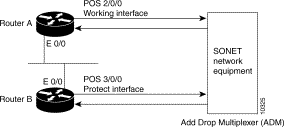
On router A, which contains the working interface, use the following configuration:
router# configure terminal
router(config)# interface loopback 1
router(config-if)# ip address 7.7.7.7 255.255.255.0
router(config)# interface pos 2/0/0
router(config-if)# aps group 1
router(config-if)# aps working 1
router(config-if)# pos ais-shut
router(config-if)# end
router#
On router B, which contains the protect interface, use the following configuration:
router# configure terminal
router(config)# interface loopback 2
router(config-if)# ip address 7.7.7.6 255.255.255.0
router(config)# interface pos 3/0/0
router(config-if)# aps group 1
router(config-if)# aps protect 1 7.7.7.7
router(config-if)# pos ais-shut
router(config-if)# end
router#
To verify the configuration or to determine if a switchover has occurred, use the show aps command.
To configure more than one protect/working interface on a router, you must use the aps group command. The following example shows the configuration of grouping more than one working/protect interface on a router. In this example, router A is configured with a working interface and a protect interface, and router B is configured with a working interface and a protect interface. If the working interface 2/0/0 on router A becomes unavailable, the connection will switchover to the protect interface 3/0/0 on router B because they are both in APS group 10. Similarly, if the working interface 2/0/0 on router B becomes unavailable, the connection will switchover to the protect interface 3/0/0 on router A because they are both in APS group 20.
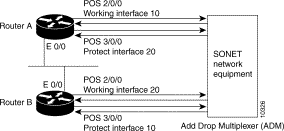 Multiple Working and Protect Interfaces Configuration
On router A, which contains the working interface for group 10 and the protect interface for group 20, use the following configuration:
router# configure terminal
router(config)# interface loopback 1
router(config-if)# ip address 7.7.7.6 255.255.255.0
router(config)# interface pos 2/0/0
router(config)# aps group 10
router(config-if)# aps working 1
router(config)# interface pos 3/0/0
router(config-if)# aps group 20
router(config-if)# aps protect 1 7.7.7.7
router(config-if)# pos ais-shut
router(config-if)# end
router#
On router B, which contains the protect interface for group 10 and the working interface for group 20, use the following configuration:
router# configure terminal
router(config)# interface loopback 2
router(config-if)# ip address 7.7.7.7 255.255.255.0
router(config)# interface pos 2/0/0
router(config)# aps group 20
router(config-if)# aps working 1
router(config)# interface pos 3/0/0
router(config-if)# aps group 10
router(config-if)# aps protect 1 7.7.7.6
router(config-if)# pos ais-shut
router(config-if)# end
router#
To verify the configuration or to determine if a switchover has occurred, use the show aps command.
This section documents new or modified commands. All other commands used with this feature are documented in the Cisco IOS Release 11.1 command references.
To enable authentication and specify the string that must be present to accept any packet on the out of band (OOB) communications channel, use the aps authenticate interface command. To disable authentication, use the no form of the command.
aps authenticate string
string | Text that must be present to accept the packet on a protected or working interface. Up to 8 alphanumeric characters are accepted. |
Authentication is disabled.
Interface configuration
This command first appeared in Cisco IOS Release 11.1 CC.
Use the aps authenticate command to ensure that only valid packets are accepted on the OOB communication channel.
The aps authenticate command must be configured on both the working and protect interfaces.
The following example enables authentication on POS interface 0 in slot 4:
router# configure terminal
router(config)# interface pos 4/0/0
router(config-if)# aps working 1
router(config-if)# aps authenticate sanjose
router(config-if)# exit
router(config)# exit
router#
To manually switch the specified circuit to a protect interface, unless a request of equal or higher priority is in effect, use the aps force interface configuration command. To cancel the switch, use the no form of the command.
aps force circuit-number
circuit-number | Number of the circuit to switch to the protect interface. |
No circuit is switched.
Interface configuration
This command first appeared in Cisco IOS Release 11.1 CC.
Use the aps force command to manually switch the interface to a protect interface when you are not using the aps revert command. For example, if you need to change the fiber connection, you can manually force the working interface to switch to the protect interface.
You can use the aps force 0 command to force traffic from the protect interface back onto the working interface. This is true only because APS always has one-plus-one (1+1) architecture.
The aps force command has a higher priority than any of the signal failures or the aps manual command.
The aps force command is configured only on protect interfaces.
The aps force command takes effect immediately and is not saved with the configuration.
The following example forces the circuit on POS interface 0 in slot 3 (a protect interface) back onto a working interface:
router# configure terminal
router(config)# interface pos 3/0/0
router(config-if)# aps protect 1
router(config-if)# aps force 1
router(config-if)# exit
router(config)# exit
router#
aps manual
aps protect
aps working
To allow more than one protect and working interface to be supported on a router, use the aps group interface configuration command. To remove a group, use the no form of the command.
aps group group-number
group-number | Number of the group. The default group number is 0. |
No groups exist.
Interface configuration
This command first appeared in Cisco IOS Release 11.1 CC.
The aps group command specifies a protect-group number for the protect or working circuit to which it applies.
The aps group command must be configured on both the protect and working interfaces.
The aps group command should appear before the aps working or aps protect command.
The aps group command specifies how the various working and protect circuits are associated. The aps group command must be configured on both the protect and working interfaces.
The following example configures two working/protect interface pairs. Working interface (3/0/0) is configured in group 10 (the protect interface for this working interface is configured on another router), and protect interface (2/0/1) is configured in group 20:
router# configure terminal
router(config)# interface loopback 1
router(config-if)# ip address 7.7.7.6 255.255.255.0
router(config)# interface pos 3/0/0
router(config-if)# aps group 10
router(config-if)# aps working 1
router(config)# interface pos 2/0/1
router(config-if)# aps group 20
router(config-if)# aps protect 1 7.7.7.7
router(config-if)# end
On the second router, protect interface (4/0/0) is configured in group 10, and working interface (5/0/0) is configured in group 20 (the protect interface for this working interface is configured on another router):
router(config)# interface loopback 2
router(config-if)# ip address 7.7.7.7 255.255.255.0
router(config)# interface pos 4/0/0
router(config-if)# aps group 10
router(config-if)# aps protect 1 7.7.7.6
router(config)# interface pos 5/0/0
router(config-if)# aps group 20
router(config-if)# aps working 1
router(config)# end
router#
To prevent a working interface from switching to a protect interface, use the aps lockout interface configuration command. To remove the lockout, use the no form of the command.
aps lockout circuit-number
circuit-number | Number of the circuit to lock out. |
No lockout exists.
Interface configuration
This command first appeared in Cisco IOS Release 11.1 CC.
The aps lockout command is configured only on protect interfaces.
The following example locks out (that is, prevents the circuit from switching to a protect interface in the event that the working circuit becomes unavailable) the POS interface 3/0/0:
router# configure terminal
router(config)# interface pos 3/0/0
router(config-if)# aps protect 1 7.7.7.7
router(config-if)# aps lockout 1
router(config-if)# end
router#
To manually switch a circuit to a protect interface, use the aps manual interface configuration command. To cancel the switch, use the no form of the command.
aps manual circuit-number
circuit-number | Number of the circuit to switch to a protect interface. |
No circuit is switched.
Interface configuration
This command first appeared in Cisco IOS Release 11.1 CC.
Use the aps manual command to manually switch the interface to a protect interface. For example, you can use this feature when you need to perform maintenance on the working channel. If a protection switch is already up, you can also use the aps manual command to revert the communication link back to the working interface before the wait to restore (WTR) time has expired. The WTR time period is set by the aps revert command.
In a one-plus-one (1+1) configuration only, you can use the aps manual 0 command to force traffic from the protect interface back onto the working interface.
The aps manual command is a lower priority than any of the signal failures or the aps force command.
The following example forces the circuit on POS interface 0 in slot 3 (a working interface) back onto the protect interface:
router# configure terminal
router(config)# interface pos 3/0/0
router(config-if)# aps working 1
router(config-if)# aps manual 1
router(config-if)# end
router#
aps force
aps protect
aps revert
aps working
To enable a POS interface as a protect interface, use the aps protect interface command. To remove the POS interface as a protect interface, use the no form of the command.
circuit-number | Circuit number of the associated working POS interface. |
ip-address | IP address of the router that has the working POS interface. |
No circuit is protected.
Interface configuration
This command first appeared in Cisco IOS Release 11.1 CC.
Use the aps protect command to configure the POS interface as backup to a specific working interface if the working interface becomes unavailable due to a router failure, degradation or loss of channel signal, or manual intervention.
The following example configures circuit 1 on POS interface 5/0/0 as a protect interface for the working interface on the router with the IP address of 7.7.7.7. For information on how to configure the working interface, refer to the aps working command.
router# configure terminal
router(config)# interface pos 5/0/0
router(config-if)# aps protect 1 7.7.7.7
router(config-if)# end
router#
To enable automatic switchover from the protect interface to the working interface after the working interface becomes available, use the aps revert interface command. To disable automatic switchover, use the no form of the command.
aps revert minutes
minutes | Number of minutes until the circuit is switched back to the working interface after the working interface is available. |
Automatic switchover is disabled.
Interface configuration
This command first appeared in Cisco IOS Release 11.1 CC.
Use the aps revert command to return the circuit to the working interface when it becomes available.
The aps revert command is configured only on protect interfaces.
The following example enables circuit 1 on POS interface 5/0/0 to revert to the working interface after the working interface has been available for 3 minutes:
router# configure terminal
router(config)# interface pos 5/0/0
router(config-if)# aps protect 1 7.7.7.7
router(config-if)# aps revert 3
router(config-if)# end
router#
To change the time between hello packets and the time before the protect interface process declares a working interface's router to be down, use the aps timers interface configuration command. To return to the default timers, use the no form of the command.
aps timers seconds1 seconds2
seconds1 | Number of seconds to wait before sending a hello packet (hello timer). The default is 1 second. |
seconds2 | Number of seconds to wait to receive a response from a hello packet before the interface is declared down (hold timer). The default is 3 seconds. |
Hello time is 1 second, and hold time is 3 seconds.
Interface configuration
This command first appeared in Cisco IOS Release 11.1 CC.
Use the aps timers command to control the time between an automatic switchover from the protect interface to the working interface after the working interface becomes available.
The hold timer and hello timer control aspects of the OOB communications.
Normally, the hold time is greater than or equal to three times the hello time.
The aps timers command is configured only on protect interfaces.
The following example specifies a hello time of 2 seconds and a hold time of 6 seconds on circuit 1 on POS interface 5/0/0:
router# configure terminal
router(config)# interface pos 5/0/0
router(config-if)# aps working 1
router(config-if)# aps timers 2 6
router(config-if)# end
router#
To configure a protect interface for unidirectional mode, use the aps unidirectional interface configuration command. To return to the default, bidirectional mode, use the no form of the command.
aps unidirectionalThis command has no keywords or arguments
Bidirectional mode.
Interface configuration
This command first appeared in Cisco IOS Release 11.1 CC.
Use the aps unidirectional command when you must interoperate with SONET network equipment (ADMs) that supports unidirectional mode.
The aps unidirectional command is configured only on protect interfaces.
The following example configures POS interface 3/0/0 for unidirectional mode:
router# configure terminal
router(config)# interface pos 3/0/0
router(config-if)# aps unidirectional
router(config-if)# aps protect 1 7.7.7.7
router(config-if)# end
router#
To configure a POS interface as a working interface, use the aps working interface command. To remove the protect from the POS interface, use the no form of the command.
circuit-number | Circuit number associated with this working interface. |
No circuit is configured as working.
Interface configuration
This command first appeared in Cisco IOS Release 11.1 CC.
When a working interface becomes unavailable because of a router failure, degradation or loss of channel signal, or manual intervention, the circuit is switched to the protect interface to maintain the connection.
To enable the circuit on the protect interface to switch back to the working interface after the working interface becomes available again, use the aps revert interface configuration command.
The following example configures the POS interface 0 in slot 4 as a working interface. For information on how to configure the protect interface, refer to the aps protect command.
router# configure terminal
router(config)# interface pos 4/0/0
router(config-if)# aps working 1
router(config-if)# end
router#
To send the alarm indication signal - line (AIS-L) when the POS interface is placed in administrative shut down state, use the pos ais-shut interface command. Use the no form of the command to disable sending LAIS on administrative shut down.
[no] pos ais-shutThis command has no keywords or arguments.
No line alarm indication signal is sent.
Interface configuration
This command first appeared in Cisco IOS Release 11.1 CC and Cisco IOS Release 11.2 GS.
In Automatic Protection Switching (APS) environments, AIS-L can be used to force a protection switch.
Prior to Release 11.2(11)GS2, when a POS interface shut down the framer was reset. In 11.2(11)GS2 and later 11.2GS releases, the framer no longer is reset when a POS interface is shut down. The pos ais-shut interface configuration command controls whether an Alarm Indication Signal - Line (AIS-L) is sent when a POS interface is shut down.
It is possible for an interface to shut down silently (no alarm) if pos ais-shut is not configured. For more information on APS, refer to Automatic Protection Switching of Packet-over-Sonet Circuits.
The following example forces the alarm indication on the POS OC-3 interface 0 in slot 3:
router# pos 3/0 ais-shut
To permit selected SONET alarms to be logged to the console for a POS interface, use the pos report interface command. To disable logging of select SONET alarms, use the no form of this command.
pos report {b1-tca | b2-tca | b3-tca | lais | lrdi | pais | plop | prdi | rdool | sd-ber | sf-ber |
b1-tca | Report B1 bit error rate (BER) threshold crossing alarm errors. Reported by default. |
b2-tca | Report B2 BER threshold crossing alarm errors. Reported by default. |
b3-tca | Report B3 BER threshold crossing alarm errors. Reported by default. |
lais | Report line alarm indication signal errors. |
lrdi | Report line remote defect indication errors. |
pais | Report path alarm indication signal errors. |
plop | Report path loss of pointer errors. Reported by default. |
prdi | Report path remote defect indication errors. |
rdool | Report receive data out of lock errors. |
sd-ber | Report signal degradation BER errors. |
sf-ber | Report signal failure BER errors. Reported by default. |
slof | Report section loss of frame errors. Reported by default. |
slos | Report section los of signal errors. Reported by default. |
b1-tca, b2-tca, b3-tca, plop, sf-ber, slof, and slos are reported by default.
Interface configuration
This command first appeared in Cisco IOS Release 11.1 CC.
Reporting an alarm means that the alarm can be logged to the console. Just because an alarm is permitted to be logged does not guarantee that it is logged. SONET alarm hierarchy rules dictate that only the most severe alarm of an alarm group is reported. Whether an alarm is reported or not, you can view the current state of a defect by checking the "Active Defects" line from the show controllers pos command output. A defect is a problem indication that is a candidate for an alarm.
For B1, the bit interleaved parity error report is calculated by comparing the BIP-8 code with the BIP-8 code extracted from the B1 byte of the following frame. Differences indicate that section level bit errors have occurred.
For B2, the bit interleaved parity error report is calculated by comparing the BIP-8/24 code with the BIP-8 code extracted from the B2 byte of the following frame. Differences indicate that line level bit errors have occurred.
For B3, the bit interleaved parity error report is calculated by comparing the BIP-8 code with the BIP-8 code extracted from the B3 byte of the following frame. Differences indicate that path level bit errors have occurred.
PAIS is sent by line terminating equipment (LTE) to alert the downstream path terminating equipment (PTE) that it has detected a defect on its incoming line signal.
PLOP is reported as a result of an invalid pointer (H1, H2) or an excess number of new data flag (NDF) enabled indications.
SLOF is detected when a severely error framing (SEF) defect on the incoming SONET signal persists for 3 milliseconds.
SLOS is detected when an all-zeros pattern on the incoming SONET signal lasts 19(+-3) microseconds or longer. This defect might also be reported if the received signal level drops below the specified threshold.
To determine the alarms that are reported on the interface, use the show controllers pos command.
The following example enables reporting of SD-BER and LAIS alarms on the interface:
Router(config)# interface pos 3/0/0
Router(config-if)# pos report sd-ber
Router(config-if)# pos report lais
Router(config-if)# end
Router#
interface pos
show controllers pos
To set the BER threshold values of the specified alarms for a POS interface, use the pos threshold interface command. To return to the default setting, use the no form of this command.
pos threshold {b1-tca | b2-tca | b3-tca | sd-ber | sf-ber} rate
b1-tca | B1 bit error rate (BER) threshold crossing alarm. |
b2-tca | B2 BER threshold crossing alarm. |
b3-tca | B3 BER threshold crossing alarm. |
sd-ber | Signal degrade BER threshold. |
sf-ber | Signal failure BER threshold. |
rate | Bit error rate from 3 to 9 (10-n). The default is 6 for all thresholds except for the sf-ber. For sf-ber, the default is 3 (that is, 10e-3). |
The default is 6 for b1-tca, b2-tca, b3-tca, and sd-ber. The default is 3 for sf-ber.
Interface configuration
This command first appeared in Cisco IOS Release 11.1 CC.
For B1, the bit interleaved parity error report is calculated by comparing the BIP-8 code with the BIP-8 code extracted from the B1 byte of the following frame. Differences indicate that section level bit errors have occurred.
For B2, the bit interleaved parity error report is calculated by comparing the BIP-8/24 code with the BIP-8 code extracted from the B2 byte of the following frame. Differences indicate that line level bit errors have occurred.
For B3, the bit interleaved parity error report is calculated by comparing the BIP-8 code with the BIP-8 code extracted from the B3 byte of the following frame. Differences indicate that path level bit errors have occurred.
SF-BER and SD-BER are sourced from B2 BIP-8 error counts (as is B2-TCA). However, SF-BER and SD-BER feed into the APS machine and can lead to a protection switch (if APS is configured).
B1-TCA, B2-TCA, and B3-TCA do nothing more than print a log message to the console (if reports for them are enabled).
To determine the BER thresholds configured on the interface, use the show controllers pos command.
The following example configures thresholds on the interface:
Router(config)# interface pos 3/0/0
Router(config-if)# pos threshold sd-ber 8
Router(config-if)# pos threshold sf-ber 4
Router(config-if)# pos threshold b1_tca 4
Router(config-if)# end
Router#
interface pos
show controllers pos
To display information about the current automatic protection switching (APS) feature, use the show aps EXEC command.
show apsThis command has no arguments or keywords.
Privileged EXEC
This command first appeared in Cisco IOS Release 11.1 CC.
The following is sample output of the show aps command on a router configured with a working interface. In this example, POS interface 0/0/0 is configured as a working interface in group 1, and the interface is selected (that is, active).
router1# show aps
POS0/0/0 working group 1 channel 1 Enabled Selected
The following is sample output of the show aps command on a router configured with a protect interface. In this example, POS interface 2/0/0 is configured as a protect interface in group 1, and the interface is not selected (the ~ indicates that the interface is not active). The output also shows that the working channel is located on the router with the IP address 15.1.6.1 and that the interface is currently selected (that is, active).
router2# show aps
POS2/0/0 protect group 1 channel 0 bidirectional ~Selected
For the K1 field (8 bits), the first 4 bits indicate the channel number that has made the request, and the last 4 bits map to the the requests (local or external) listed in Table 1. Under most conditions, the K1 bits are not displayed. For K2 field (8 bits), the first 4 bits indicate the channel number bridged onto the protect line, the next bit is the architecture used, and the last 3 bits indicate the mode of operation or non-APS use listed in Table 2. A show controller pos command displays K2 values.
| Bits (hex) | Description |
|---|---|
| K1 Bits 87654321 |
|
| Bits 8 through 5 |
|
nnnn | Channel number that made the request. |
| Bits 4 through 1 |
|
1111 (0xF) | Lockout of protection request. |
1110 (0xE) | Forced switch request. |
1101 (0xD) | Signal failure (SF)---high priority request. |
1100 (0xC) | Signal failure (SF)---low priority request. |
1011 (0xB) | Signal degradation (SD)---high priority request. |
1010 (0xA) | Signal degradation (SD)---low priority request. |
1001 (0x9) | Not used. |
1000 (0x8) | Manual switch request. |
0111 (0x7) | Not used. |
0110 (0x6) | Wait to restore request. |
0101 (0x5) | Not used. |
0100 (0x4) | Exercise request. |
0011 (0x3) | Not used. |
0010 (0x2) | Reverse request. |
0001 (0x1) | Do not revert request. |
0000 (0x0) | No request. |
| Bits | Description |
|---|---|
| K2 Bits 87654321 |
|
| Bits 8 through 5 |
|
nnnn | Channel number bridged on the protection line. |
| Bit 4 |
|
1 | One to n (1:n) architecture. |
0 | One plus one (1+1) architecture. |
| Bits 3 through 1 |
|
111 | Line AIS. |
110 | Line RDI. |
101 | Bidirectional operation mode. |
100 | Unidirectional operation mode. |
other | Reserved. |
To display information about the POS controllers, use the show controllers pos privileged EXEC command.
show controllers pos [slot-number] [details]
slot-number | (Optional) The chassis slot that contains the POS interface. For the Cisco 7500 series, use slot/port-adapter/port (for example, 2/0/0). For the Cisco 12000 series, use slot/port (for example, 4/0). The "/" is required. If you do not specify a slot number, information for all the installed POS controllers is displayed. |
details | (Optional) In addition to the normal information displayed by the show controllers pos command, the details option provides a hexadecimal and ASCII "dump" of the path trace buffer. |
Privileged EXEC
This command first appeared in Cisco IOS Release 11.1 CC and 11.2 GS.
The information displayed is generally useful for diagnostic tasks performed by technical support personnel only.
The following is sample output of the show controllers pos command on a Cisco 7500 series router:
router# show controllers pos
POS2/0/0
SECTION
  LOF = 0          LOS = 2335                         BIP(B1) = 77937133
LINE
  AIS = 2335       RDI = 20         FEBE = 3387950089 BIP(B2) = 1622825387
PATH
  AIS = 2340       RDI = 66090      FEBE = 248886263  BIP(B3) = 103862953
  LOP = 246806     NEWPTR = 11428072   PSE = 5067357     NSE = 4645
Active Defects: B2-TCA B3-TCA
Active Alarms:  None
Alarm reporting enabled for: B1-TCA
APS
  COAPS = 12612784   PSBF = 8339
  State: PSBF_state = False
  Rx(K1/K2): 00/CC  Tx(K1/K2): 00/00
  S1S0 = 03, C2 = 96
CLOCK RECOVERY
  RDOOL = 64322060
  State: RDOOL_state = True
PATH TRACE BUFFER: UNSTABLE
  Remote hostname :
  Remote interface:
  Remote IP addr  :
  Remote Rx(K1/K2): ../..  Tx(K1/K2): ../..
BER thresholds:  SF = 10e-3  SD = 10e-8
TCA thresholds:  B1 = 10e-7   B2 = 10e-3  B3 = 10e-6
router#
Table 3 describes the fields shown in the display.
| Field | Description |
|---|---|
POS2/0/0 | Slot number of the POS interface. |
LOF | Section loss of frame is detected when a severely error framing (SEF) defect on the incoming SONET signal persist for 3 milliseconds. |
LOS | Section loss of signal is detected when an all-zeros pattern on the incoming SONET signal lasts 19(+-3) microseconds or longer. This defect might also be reported if the received signal level drops below the specified threshold. |
BIP(B1)/BIP(B2)/BIP(B3) | Bit interleaved parity error reported. For B1, the bit interleaved parity error report is calculated by comparing the BIP-8 code with the BIP-8 code extracted from the B1 byte of the following frame. Differences indicate that section level bit errors have occurred. For B2, the bit interleaved parity error report is calculated by comparing the BIP-8/24 code with the BIP-8 code extracted from the B2 byte of the following frame. Differences indicate that line level bit errors have occurred. For B3, the bit interleaved parity error report is calculated by comparing the BIP-8 code with the BIP-8 code extracted from the B3 byte of the following frame. Differences indicate that path level bit errors have occurred. |
AIS | Alarm indication signal. Line alarm indication signal is sent by the section terminating equipment (STE) to alert the downstream line terminating equipment (LTE) that a LOS or LOF defect has been detected on the incoming SONET section. Path alarm indication signal is sent by the LTE to alert the downstream path terminating equipment (PTE) that it has detected a defect on its incoming line signal. |
RDI | Remote defect indication. Line remote defect indication is reported by the downstream LTE when it detects LOF, LOS, or AIS. Path remote defect indication is reported by the downstream PTE when it detects a defect on the incoming signal. |
FEBE | Far end block errors. Line far end block error (accumulated from the M0 or M1 byte) is reported when the downstream LTE detects BIP(B2) errors. Path far end block error (accumulated from the G1 byte) is reported when the downstream PTE detects BIP(B3) errors. |
LOP | Path loss of pointer is reported as a result of an invalid pointer (H1, H2) or an excess number of new data flag (NDF) enabled indications. |
NEWPTR | An inexact count of the number of times the SONET framer has validated a new SONET pointer value (H1,H2). |
PSE | An inexact count of the number of times the SONET framer has detected a positive stuff event in the received pointer (H1, H2). |
NSE | An inexact count of the number of times the SONET framer has detected a negative stuff event in the received pointer (H1, H2). |
Active Defects | List of all currently active SONET defects. |
Active Alarms | List of current Alarms as enforced by Sonet Alarm Hierarchy. |
Alarm reporting enabled for | List of alarms that you enabled reporting for with the pos report interface command. |
APS | Automatic protection switching. |
COAPS | An inexact count of the number of times a new APS value has been detected in the K1, K2 bytes. |
PSBF | An inexact count of the number of times a protection switching byte failure has been detected (no three consecutive SONET frames contain identical K1 bytes). |
PSBF_state | Protection switching byte failure state. |
Rx(K1/K2)/Tx(K1/K2) | Contents of the received and transmitted K1 and K2 bytes. For more information on the K1 field, refer to Table 1. For more information on the K2 field, refer to Table 2. |
S1S0 | The two S bits received in the last H1 byte. |
C2 | The value extracted from the SONET path signal label byte (C2). |
CLOCK RECOVERY | SONET clock is recovered using information in the SONET overhead. RDOOL is an inexact count of the number of times Receive Data Out Of Lock has been detected which indicates the clock recovery phased lock loop is unable to lock to the receive stream. |
PATH TRACE BUFFER | SONET path trace buffer is used to communicate information regarding the remote hostname, interface name/number and IP address. This is a Cisco-proprietary use of the J1 (path trace) byte. |
BER thresholds | List of the bit error rate (BER) thresholds you configured with the pos threshold interface command. |
TCA thresholds | List of threshold crossing alarms (TCA) you configured with the pos threshold interface command. |
|
|