|
|

This chapter describes the basic tasks that you can perform to manage the general system features of the Cisco IOS software--those features that are generally not specific to a particular protocol. Cisco's system management features are supported through the Simple Network Management Protocol (SNMP). Cisco supports the SNMP Version 1 protocol, referred to as SNMPv1, and the SNMP Version 2 protocol, referred to as SNMPv2. This chapter describes the tasks needed to configure SNMP support on Cisco routers. A part of SNMP is the Management Information Base (MIB). MIBs provide variables that can be set or read to change parameters or provide information on network devices and interfaces. Cisco supports several MIBs, including the Internet standard MIB II, and also provides its own Cisco MIB. For information on the Cisco MIB, see the Cisco Management Information Base (MIB) User Quick Reference.
Cisco Systems also provides CiscoWorks, a feature-rich network management application suite that is integrated with Sun Microsystems' SunNet Manager product running on a Sun SPARCstation platform. CiscoWorks provides a menu-driven graphical user interface and supports all five areas of network management. (See the next section, "Understanding System Management," for details.) With CiscoWorks, you can create network maps and set up automated network performance monitors and fault tests, such as pinpointing connectivity problems. Test results can be displayed in several graph formats. Refer to CiscoWorks online help for information on how to use CiscoWorks on a Sun SPARCstation. See the CiscoWorks Installation and Reference Guide for installation and reference information.
In addition to CiscoWorks for the Sun SPARCstation platform, Cisco Systems provides CiscoWorks for Windows. CiscoWorks for Windows incorporates the features of the Cisco Configuration Builder, which was based on an MS-Windows graphical user interface. CiscoWorks for Windows replaces the Cisco Configuration Builder, previously provided for configuring Cisco routers. For information on how to use CiscoWorks for Windows, refer to the online help provided with the product and the CiscoWorks for Windows Getting Started Guide.
For a list of recommended books on network management, refer to the appendix "References and Recommended Reading" in the Configuration Fundamentals Command Reference.
For a complete description of the commands mentioned in this chapter, refer to the "System Management Commands" chapter of the Configuration Fundamentals Command Reference.
This chapter describes the tasks you can perform to manage the router and its performance on the network. In general, system or network management falls into the categories described in the following sections:
You can complete any of the tasks in the following sections to perform configuration management functions:
Other configuration management tasks are described in the "Loading Images and Configuration Files" chapter.
| Task | Command |
|---|---|
| Customize the prompt. | prompt string |
| Remove the configuration prompt (config). | no service prompt config |
One of the first basic tasks is to name your router. The name is considered the host name and is the name that is displayed by the system prompt. If no name is configured, the system default name is Router. You can name the router in global configuration mode as follows:
| Task | Command |
|---|---|
| Set the host name. | hostname name |
For an example of configuring a router name, see the section "System Configuration File Example" at the end of this chapter.
You can create aliases for commonly used or complex commands. Use word substitutions or abbreviations to tailor command syntax for you and your user community.
To create and display command aliases, perform the tasks in the following sections:
To create a command alias, perform the following task in global configuration mode:
| Task | Command |
|---|---|
| Configure a command alias. | alias mode alias-name alias-command-line |
To display alias names and the original command syntax, perform the following task in EXEC mode:
| Task | Command |
|---|---|
| Show all command aliases and original command syntax, or specify the aliases in a particular command mode. | show aliases [mode] |
You can change the period of time over which a set of data is used for computing load statistics. By decreasing the load interval, dial backup and other decisions are based on an average that is computed over a shorter period of time and is more responsive to bursts of traffic.
To change the length of time for which a set of data is used to compute load statistics, perform the following task in interface configuration mode:
| Task | Command |
|---|---|
| Set the length of time for which data is used for load calculations. | load-interval seconds |
All Cisco routers provide an array of time-of-day services. These services allow the products to accurately keep track of the current time and date, to synchronize multiple products to the same time, and to provide time services to other systems.
The heart of the time service is the system clock. This clock runs from the moment the system starts up and keeps track of the current date and time. The system clock can be set from a number of sources and in turn can be used to distribute the current time through various mechanisms to other systems. When a Cisco 7000 series is initialized, the system clock is set based on the time in the hardware; on other models, the system clock it is set to midnight on March 1, 1993. The system clock can then be set from the following sources:
The system clock can provide time to the following services:
The system clock keeps track of time internally based on Coordinated Universal Time (UTC), also known as Greenwich Mean Time (GMT). You can configure information about the local time zone and summer time (daylight savings time) so that the time is displayed correctly relative to the local time zone.
The system clock keeps track of whether the time is "authoritative" or not (that is, whether it has been set by a time source considered to be authoritative). If it is not authoritative, the time will be available only for display purposes and will not be redistributed.
The Network Time Protocol (NTP) is a protocol designed to time-synchronize a network of machines. NTP runs over UDP, which in turn runs over IP. NTP is documented in RFC 1305.
An NTP network usually gets its time from an authoritative time source, such as a radio clock or an atomic clock attached to a time server. NTP then distributes this time across the network. NTP is extremely efficient; no more than one packet per minute is necessary to synchronize two machines to within a millisecond of one another.
NTP uses the concept of a "stratum" to describe how many NTP "hops" away a machine is from an authoritative time source. A "stratum 1" time server has a radio or atomic clock directly attached, a "stratum 2" time server receives its time via NTP from a "stratum 1" time server, and so on. A machine running NTP will automatically choose as its time source the machine with the lowest stratum number that it is configured to communicate with via NTP. This strategy effectively builds a self-organizing tree of NTP speakers.
NTP is careful to avoid synchronizing to a machine whose time may not be accurate. It avoids doing so in two ways. First of all, NTP will never synchronize to a machine that is not in turn synchronized itself. Secondly, NTP will compare the time reported by several machines, and will not synchronize to a machine whose time is significantly different than the others, even if its stratum is lower.
The communications between machines running NTP (known as "associations") are usually statically configured; each machine is given the IP address of all machines with which it should form associations. Accurate timekeeping is made possible by exchanging NTP messages between each pair of machines with an association. However, in a local-area network (LAN) environment, NTP can be configured to use IP broadcast messages instead. This alternative reduces configuration complexity because each machine can simply be configured to send or receive broadcast messages. However, the accuracy of timekeeping is marginally reduced because the information flow is one-way only.
Cisco's implementation of NTP does not support stratum 1 service; in other words, it is not possible to connect to a radio or atomic clock. It is recommended that time service for your network be derived from the public NTP servers available in the IP Internet. If the network is isolated from the Internet, Cisco's implementation of NTP allows a machine to be configured so that it acts as though it is synchronized via NTP, when in fact it has determined the time using other means. Other machines then synchronize to that machine via NTP.
When multiple sources of time (VINES, Cisco 7000 calendar, manual configuration) are available, NTP is always considered to be more authoritative. NTP time overrides the time set by any other method.
A number of manufacturers include NTP software for their host systems, and a publicly available version for systems running UNIX and its various derivatives is also available. This software allows host systems to be time-synchronized as well.
Simple Network Time Protocol (SNTP) is a simplified, client-only version of NTP for use on Cisco 1003, Cisco 1004, and Cisco 1005 routers. SNMP can only receive the time from NTP servers; it cannot be used to provide time services to other systems.
SNTP typically provides time within 100 milliseconds of the accurate time, but it does not provide the complex filtering and statistical mechanisms of NTP. In addition, SNTP does not authenticate traffic, although you can configure extended access lists to provide some protection. An SNTP client is more vulnerable to misbehaving servers than an NTP client and should only be used in situations where strong authentication is not required.
You can configure SNTP to request and accept packets from configured servers or to accept NTP broadcast packets from any source. When multiple sources are sending NTP packets, the server with the best stratum is selected. If multiple servers are at the same stratum, a configured server is preferred over a broadcast server. If multiple servers pass both tests, the first one to send a time packet is selected. SNTP will only choose a new server if it stops receiving packets from the currently selected server, or if a better server (according to the above criteria) is discovered.
Time service is also available when Banyan VINES is configured. This protocol is a standard part of VINES. Cisco's implementation allows the VINES time service to be used in two ways. First, if the system has learned the time from some other source, it can act as a VINES time server and provide time to other machines running VINES. It also can use the VINES time service to set the system clock if no other form of time service is available.
The Cisco 7000 contains a battery-powered calendar system that tracks the date and time across system restarts and power outages. This calendar system is always used to initialize the system clock when the system is restarted. It can also be considered to be an authoritative source of time and be redistributed via NTP or VINES time service if no other source is available. Furthermore, if NTP is running, the Cisco 7000 calendar can be periodically updated from NTP, compensating for the inherent drift in the calendar time.
NTP services are enabled on all interfaces by default. The optional tasks you can perform are documented in the following sections:
If you want to authenticate the associations with other systems for security purposes, perform the tasks that follow. The first task enables the NTP authentication feature. The second task defines each of the authentication keys. Each key has a key number, a type, and a value. Currently the only key type supported is md5. Third, a list of "trusted" authentication keys is defined. If a key is trusted, this system will be ready to synchronize to a system that uses this key in its NTP packets.
To configure NTP authentication, perform the following tasks in global configuration mode:
| Task | Command |
|---|---|
| Step 1 Enable the NTP authentication feature. | ntp authenticate |
| Step 2 Define the authentication keys. | ntp authentication-key number md5 value |
| Step 3 Define trusted authentication keys. | ntp trusted-key key-number |
An NTP association can be a peer association (meaning that this system is willing to either synchronize to the other system or to allow the other system to synchronize to it), or it can be a server association (meaning that only this system will synchronize to the other system, and not the other way around). If you want to form an NTP association with another system, perform one of the following tasks in global configuration mode:
| Task | Command |
|---|---|
| Form a peer association with another system. | ntp peer ip-address [version number] [key keyid] [source interface] [prefer] |
| Form a server association with another system. | ntp server ip-address [version number] [key keyid] [source interface] [prefer] |
Note that only one end of an association needs to be configured; the other system will automatically establish the association.
See the example entitled "Clock, Calendar, and NTP Configuration Examples" at the end of this chapter.
The system can either send broadcast packets or listen to them on an interface-by-interface basis. The estimated round-trip delay for broadcast packets can also be configured. Perform one or more of the following tasks in global configuration mode if you want to use NTP's broadcast feature:
| Task | Command |
|---|---|
| Send NTP broadcast packets. | ntp broadcast [version number] |
| Receive NTP broadcast packets. | ntp broadcast client |
| Adjust estimated delay. | ntp broadcastdelay microseconds |
See the example entitled "Clock, Calendar, and NTP Configuration Examples" at the end of this chapter.
You can control NTP access on two levels by completing the following tasks:
To control access to NTP services, you can create an NTP access group and apply a basic IP access list to it. To do so, perform the following task in global configuration mode:
| Task | Command |
|---|---|
| Create an access group and apply a basic IP access list to it. | ntp access-group {query-only | serve-only | serve | peer} access-list-number |
The access group options are scanned in the following order from least restrictive to most restrictive:
1 . Peer--Allows time requests and NTP control queries and allows the system to synchronize itself to a system whose address passes the access list criteria.
2 . Serve--Allows time requests and NTP control queries, but does not allow the system to synchronize itself to a system whose address passes the access list criteria.
3 . Serve-only--Allows only time requests from a system whose address passes the access list criteria.
4 . Query-only--Allows only NTP control queries from a system whose address passes the access list criteria.
If the source IP address matches the access lists for more than one access type, the first type is granted. If no access groups are specified, all access types are granted to all systems. If any access groups are specified, only the specified access types will be granted.
For details on NTP control queries, see RFC 1305 (NTP version 3).
NTP services are enabled on all interfaces by default. You can disable NTP packets from being received through an interface by performing the following task in interface configuration mode:
| Task | Command |
|---|---|
| Disable NTP services on a specific interface. | ntp disable |
When the system sends an NTP packet, the source IP address is normally set to the address of the interface through which the NTP packet is sent. Perform the following task in global configuration mode if you want to configure a specific interface from which the IP source address will be taken:
| Task | Command |
|---|---|
| Configure an interface from which the IP source address will be taken. | ntp source interface |
This interface will be used for the source address for all packets sent to all destinations. If a source address is to be used for a specific association, use the source parameter on the ntp peer or ntp server command shown earlier in this chapter.
Perform the following task in global configuration mode if you want the system to be an authoritative NTP server, even if the system is not synchronized to an outside time source:
| Task | Command |
|---|---|
| Make the system an authoritative NTP server. | ntp master [stratum] |
 Caution Use this command with extreme caution. It is very easy to override valid time sources using this command, especially if a low stratum number is configured. Configuring multiple machines in the same network with the ntp master command can cause instability in timekeeping if the machines do not agree on the time.
For an example of configuring an authoritative NTP server, see the section "Clock, Calendar, and NTP Configuration Examples" at the end of this chapter.
Perform the following task in global configuration mode if the system is synchronized to an outside time source via NTP and you want the Cisco 7000 calendar to be synchronized periodically to NTP time:
| Task | Command |
|---|---|
| Configure NTP to update the Cisco 7000 calendar. | ntp update-calendar |
For an example of configuring NTP to update the Cisco 7000 calendar, see the section "Clock, Calendar, and NTP Configuration Examples" at the end of this chapter.
SNTP is disabled by default. In order to enable SNTP on a Cisco 1003, Cisco 1004, or Cisco 1005 router, perform one or both of the following tasks in global configuration mode:
| Task | Command |
|---|---|
| Configure SNTP to request NTP packets from an NTP server. | sntp server {address | hostname} [version number] |
| Configure SNTP to accept NTP packets from any NTP broadcast server. | sntp broadcast client |
Enter the sntp server command once for each NTP server. The NTP servers must be configured to respond to the SNTP messages from the router.
If you enter both the sntp server command and the sntp broadcast client command, the router will accept time from a broadcast server but prefers time from a configured server, assuming the strata are equal.
To display information about SNTP, use the show sntp EXEC command.
Perform the following task in global configuration mode if you want to distribute the system clock to other VINES systems:
| Task | Command |
|---|---|
| Distribute the system clock to other VINES systems. | vines time use-system1 |
To receive VINES time service to control the system clock, perform the following task in global configuration mode:
| Task | Command |
|---|---|
| Receive VINES time service. | vines time set-system1 |
If no other source of time is available, you can manually configure the current time and date after the system is restarted. The time will remain accurate until the next system restart. We recommend that you use manual configuration only as a last resort.
To set up time services, complete the following tasks as needed. If you have an outside source to which the router can synchronize, you do not need to manually set the system clock.
Complete the following task in global configuration mode to manually configure the time zone used by the Cisco IOS software:
| Task | Command |
|---|---|
| Set the time zone. | clock timezone zone hours [minutes] |
For an example of configuring the time zone, see the section "Clock, Calendar, and NTP Configuration Examples" at the end of this chapter.
To configure summer time (daylight savings time) in areas where it starts and ends on a particular day of the week each year, perform the following task in global configuration mode:
| Task | Command |
|---|---|
| Configure summer time. | clock summer-time zone recurring [week day month hh:mm week day month hh:mm [offset]] |
If summer time in your area does not follow this pattern, you can configure the exact date and time of the next summer time events by performing one of the following tasks in global configuration mode:
| Task | Command |
|---|---|
| Configure summer time. | clock summer-time zone date month date year hh:mm month date year hh:mm [offset]
or clock summer-time zone date date month year hh:mm date month year hh:mm [offset] |
For an example of configuring summer time, see the section "Clock, Calendar, and NTP Configuration Examples" at the end of this chapter.
If you have an outside source on the network that provides time services (such as an NTP server or VINES time service), you do not need to manually set the system clock.
However, if you have do not have any time service source, complete one of the following tasks in EXEC mode to set the system clock:
| Task | Command |
|---|---|
| Set the system clock. | clock set hh:mm:ss day month year
or clock set hh:mm:ss month day year |
In addition to a system clock, the Cisco 4500 and Cisco 7000 hardware provides a system calendar that can set the system time and control the system clock, as well as enable the router to act as a time service for the network.
You can complete the following tasks to enable the Cisco 4500 and Cisco 7000 calendar capabilities:
If you do not have an external time source, perform the following task in EXEC mode to set the system calendar:
| Task | Command |
|---|---|
| Set the calendar. | calendar set hh:mm:ss day month year
or calendar set hh:mm:ss month day year |
Although the system clock is always initialized from the calendar when the system is restarted, by default it is not considered to be authoritative and so will not be redistributed with NTP or VINES Time Service. To make the calendar be authoritative, complete the following task in global configuration mode:
| Task | Command |
|---|---|
| Enable the router to act as a valid time source to which network peers can synchronize. | clock calendar-valid |
For an example of making the calendar authoritative, see the section "Clock, Calendar, and NTP Configuration Examples" at the end of this chapter.
To set the system clock to the new calendar setting, perform the following task in EXEC mode:
| Task | Command |
|---|---|
| Set the system clock from the calendar. | clock read-calendar |
To update the calendar with the new clock setting, perform the following task in EXEC mode:
| Task | Command |
|---|---|
| Set the calendar from the system clock. | clock update-calendar |
To monitor clock, calendar, and NTP EXEC services, complete the following tasks in EXEC mode:
| Task | Command |
|---|---|
| Display the current calendar time (for the Cisco 4500 and Cisco 7000 series only). | show calendar |
| Display the current system clock time. | show clock [detail] |
| Show the status of NTP associations. | show ntp associations [detail] |
| Show the status of NTP. | show ntp status |
| Display information about SNTP (Cisco 1003, Cisco 1004, Cisco 1005 only). | show sntp |
You can access minor TCP, UDP, and BOOTP services available from hosts on the network. These services are enabled by default.
To enable these services, perform the following tasks in global configuration mode:
| Task | Command |
|---|---|
| Access minor TCP services such as echo, chargen, discard, and daytime. | service tcp-small-servers |
| Access minor UDP services such as echo, chargen, and discard. | service udp-small-servers |
| Access the BOOTP service. | ip bootp server |
| Task | Command |
|---|---|
| Enable the Finger protocol requests. | service finger |
You can hide addresses while attempting to establish a Telnet session. To configure the router to suppress Telnet addresses, perform the following task in global configuration mode:
| Task | Command |
|---|---|
| Hide addresses while establishing a Telnet session. | service hide-telnet-address |
Use the busy-message command with the service hide-telnet-address command to customize the information displayed during Telnet connection attempts. If the connection attempt is not successful, the router suppresses the address and displays the message specified with the busy-message command.
The Simple Network Management Protocol (SNMP) system consists of three parts: an SNMP manager, an SNMP agent, and a Management Information Base (MIB). SNMP is an application-layer protocol that allows SNMP manager and agent to communicate. SNMP provides a message format for sending information between an SNMP manager and an SNMP agent. The SNMP manager can be part of a Network Management System (NMS), such as CiscoWorks.
The agent and MIB reside on the router. To configure SNMP on the router, you define the relationship between the manager and the agent.
An agent can send unsolicited traps to the manager. Traps are messages alerting the SNMP manager to a condition on the network. Traps can indicate improper user authentication, restarts, link status (up or down), closing of a TCP connection, or loss of connection to a neighbor router.
Figure 36 illustrates the communications relationship between the SNMP manager and agent. It shows that a manager can send the agent requests to get and set MIB values. The agent can respond to these requests. Independent of this interaction, the agent can send unsolicited traps to the manager notifying the manager of network conditions.
Cisco supports the SNMP Version 1 protocol, referred to as SNMPv1, and the SNMP Version 2 protocol, referred to as SNMPv2. Cisco's implementation of SNMP supports all MIB II variables (as described in RFC 1213) and SNMP traps (as described in RFC 1215). See the Cisco Management Information Base (MIB) User Quick Reference for a list and detailed description of each Cisco MIB variable and SNMP trap.
RFC 1447, "SNMPv2 Party MIB" (April 1993), describes the managed objects that correspond to the properties associated with SNMPv2 parties, SNMPv2 contexts, and access control policies, as defined by the SNMPv2 Administrative Model. RFC 1450, "SNMPv2 MIB," (April 1993) describes the managed objects that instrument the behavior of an SNMPv2 implementation. Cisco supports the MIB variables as required by the conformance clauses specified in these MIBs.
Cisco also provides its own MIB with every system. One of the set of MIB objects provided is the Cisco Chassis MIB that enables the SNMP manager to gather data on system card descriptions, serial numbers, hardware and software revision levels, and slot locations.
Although SNMPv2 offers more robust support than SNMPv1, Cisco continues to support SNMPv1. This is because not all management stations have migrated to SNMPv2 and you must configure the relationship between the agent and the manager to use the version of SNMP supported by the management station.
SNMPv1 offers a community-based form of security defined through an IP address access control list and password. SNMPv2 offers richer security configured through an access policy that defines the relationship between a single manager and agent. SNMPv2 security includes message authentication support using the Message Digest (MD5) algorithm, but because of the Data Encryption Standard (DES) export restrictions, it does not include encryption support through DES. SNMPv2 security provides data origin authentication, ensures data integrity, and protects against message stream modification.
In addition to enhanced security, SNMPv2 support includes a bulk retrieval mechanism and more detailed error message reporting to management stations. The bulk retrieval mechanism supports the retrieval of tables and large quantities of information, minimizing the number of round-trips required.
The SNMPv2 improved error handling support includes expanded error codes that distinguish different kinds of error conditions; these conditions are reported through a single error code in SNMPv1. Error return codes now report the error type. Three kinds of exceptions are also reported: no such object exceptions, no such instance exceptions, and end of MIB view exceptions.
There is no specific command that you use to enable SNMP. The first snmp-server command that you enter enables both versions of SNMP.
To configure SNMP support, perform the tasks in one of the following sections:
To configure relationship between the agent and the manager on the router, you need to know the version of the SNMP protocol that the management station supports. An agent can communicate with multiple managers; for this reason, you can configure the Cisco IOS software to support communications with one management station using the SNMPv1 protocol and another using the SNMPv2 protocol.
You can perform tasks in the following sections to configure support for both SNMPv1 and SNMPv2:
Using SNMP packets, a network management tool can send messages to users on virtual terminals and the console. This facility operates in a similar fashion to the EXEC send command; however, the SNMP request that causes the message to be issued to the users also specifies the action to be taken after the message is delivered. One possible action is a shutdown request. After a system is shut down, typically it is reloaded. Because the ability to cause a reload from the network is a powerful feature, it is protected by the snmp-server system-shutdown global configuration command. If you do not issue this command, the shutdown mechanism is not enabled. To enable the SNMP agent shutdown mechanism, perform the following task:
| Task | Command |
|---|---|
| Use the SNMP message reload feature and request a system shutdown message. | snmp-server system-shutdown |
To understand how to use this feature with SNMP requests, read the document mib.txt available by anonymous FTP from ftp.cisco.com.
You can set the system contact, location, and serial number of the SNMP agent so that these descriptions can be accessed through the configuration file. To do so, perform one or more of the following tasks in global configuration mode:
| Task | Command |
|---|---|
| Set the system contact string. | snmp-server contact text |
| Set the system location string. | snmp-server location text |
| Set the system serial number. | snmp-server chassis-id text |
You can set the maximum packet size permitted when the SNMP agent is receiving a request or generating a reply. To do so, perform the following task in global configuration mode:
| Task | Command |
|---|---|
| Establish the maximum packet size. | snmp-server packetsize byte-count |
You can limit the TFTP servers used for saving and loading configuration files via SNMP to the servers specified in an access list. To do so, perform the following task in global configuration mode:
| Task | Command |
|---|---|
| Limit TFTP servers used for configuration file copies via SNMP to the servers in an access list. | snmp-server tftp-server-list number |
To monitor SNMP input and output statistics, including the number of illegal community string entries, errors, and requested variables, complete the following task in EXEC mode:
| Task | Command |
|---|---|
| Monitor SNMP status. | show snmp |
To disable both versions of SNMP (SNMPv1 and SNMPv2) concurrently, perform the following task in global configuration mode:
| Task | Command |
|---|---|
| Disable SNMP agent operation. | no snmp-server |
Step 1 Define a view to identify the objects that can be seen, if you do not want to use one of the standard predefined views.
Step 2 Define a context to identify the object resources that can be acted on.
Step 3 Define a party for both the manager and the agent to identify them.
Step 4 Using the definitions created in the previous tasks, configure the access policy that characterizes the communications that can occur between the manager and the agent. The privileges that you define for the access policy depend on whether the agent is defined as the source or the destination. For example:
Figure 37 shows the information exchanged between the manager and the agent. The top arrow, leading from the manager to the agent, shows the types of requests the manager can send to the agent. The bottom arrow, leading from the agent to the manager, shows the kind of information that the agent can send to the manager. Note that the agent sends trap messages to the manager in response to certain network conditions; trap messages are unsolicited and are not related to the request/response communication exchange between the manager and the agent that occurs in relation to MIB variables. For any given manager and agent relationship, the privileges defined in the access policy constrain communications to a specific set of operations.
You must create access policies for each new agent that is installed. You also must create access policies on an agent when new management stations with which the agent will communicate are installed. Moreover, every time a network address changes on a management station, you must reconfigure the access policy to reflect the new information for the management station.
This section describes each task that you must perform to configure an access policy. Then it addresses the alternative method and describes the task of configuring the user ID for the simplified security conventions method.
To configure support for SNMv2, perform the following tasks:
After you create a record, you can modify the record contents by changing one or more of the record values. To do this, issue the command again, naming the record that you created originally. You must fully specify the record values, including the argument values to remain unchanged.
To create or modify an SNMP view record, perform the following task in global configuration mode:
| Task | Command |
|---|---|
| Create or modify a view record. | snmp-server view view-name oid-tree {included | excluded} |
To remove a view record, use the no snmp-server view command.
To create or modify an SNMP context record, perform the following task in global configuration mode:
| Task | Command |
|---|---|
| Create or modify a context record. | snmp-server context context-name context-oid view-name |
To remove a context entry, use the no snmp-server context command. Specify only the name of the context. The name identifies the context to be deleted.
To create or modify an SNMPv2 party record, perform the following task in global configuration mode:
| Task | Command |
|---|---|
| Create or modify a party record. | snmp-server party party-name party-oid [protocol-address] [packetsize size] [local | remote] [authentication md5 key [clock clock] [lifetime lifetime]] |
To remove a party record, use the no snmp-server party command.
To create or modify an SNMPv2 access policy, perform the following task in global configuration mode:
| Task | Command |
|---|---|
| Create or modify an access policy. | snmp-server access-policy destination-party source-party context privileges |
The SNMP trap operations allow a system administrator to configure the agent router to send information to an SNMP manager when a particular event occurs.
To define the recipient of the trap message, you configure a party record for the manager, including the protocol address, and specify the party record as the destination party for the snmp-server access policy command. To configure the router to send traps to a host, perform the following tasks in global configuration mode:
| Task | Command |
|---|---|
| Specify the access policy that defines the traps that the agent can send to the manager. | snmp-server access-policy destination-party source-party context privileges |
| Specify the recipient of the trap message. | snmp-server host host community-string [trap-type] |
| Specify the types of traps sent. | snmp-server enable traps [trap-type] [trap-option] |
| Establish trap message authentication. | snmp-server trap-authentication [snmpv1 | snmp2] |
Optionally, you can specify a value other than the default for the source interface, message (packet) queue length for each trap host, or retransmission interval.
| Task | Command |
|---|---|
| Specify the source interface (and hence IP address) of the trap message. | snmp-server trap-source interface |
| Establish the message queue length for each trap host. | snmp-server queue-length length |
| Define how often to resend trap messages on the retransmission queue. | snmp-server trap-timeout seconds |
By default, SNMP link traps are sent when an interface goes up or down. For interfaces expected to go up and down during normal usage, such as ISDN interfaces, the output generated by these traps may not be useful. Use the no snmp trap link-status command to disable these traps.
Because SNMP traps are inherently unreliable and much too important to lose, at least one syslog message, the most recent, is stored in a history table on the router. You can also specify the level of syslog traps (Cisco Syslog MIB) that get stored in the history table and sent to the SNMP network management station. For information on the history table, refer to the "Define the Error Message Severity Level and Facilities" section later in this chapter.
Using the snmp-server community command, you specify a string, and, optionally, a MIB view and an access list. The string is used as a password. The MIB view defines the subset of all MIB objects that the given community may access. The access list identifies the IP addresses of systems on which SNMPv1 managers reside that might use the community string to gain access to the SNMPv1 agent.
To configure support for SNMPv1, you perform tasks in the following sections:
You can also configure the router to restrict SNMPv1 agents using SNMPv2 security methods. In this case, use the snmp-server party authentication snmpv1 command to associate a given community string with a party. Configure thehe context and access policy as described in the SNMPv2 section.
To configure a community string, perform the following task in global configuration mode:
| Task | Command |
|---|---|
| Define the community access string. | snmp-server community string [view view-name] [ro | rw] [access-list number] |
You can configure one or more community strings. To remove a specific community string, use the no snmp-server community command.
For an example of configuring a community string, see the section "System Configuration File Example" at the end of this chapter.
The SNMP trap operations allow a system administrator to configure the agent router to send information to an SNMP manager when a particular event occurs.
To configure the router to send traps to a host, perform the following tasks in global configuration mode:
| Task | Command |
|---|---|
| Specify the recipient of the trap message. | snmp-server host host community-string [trap-type] |
| Specify the types of traps sent. | snmp-server enable traps [trap-type] [trap-option] |
| Establish trap message authentication. | snmp-server trap-authentication [snmpv1 | snmp2] |
Optionally, you can specify a value other than the default for the source interface, message (packet) queue length for each trap host, or retransmission interval.
| Task | Command |
|---|---|
| Specify the source interface (and hence IP address) of the trap message. | snmp-server trap-source interface |
| Establish the message queue length for each trap host. | snmp-server queue-length length |
| Define how often to resend trap messages on the retransmission queue. | snmp-server trap-timeout seconds |
By default, SNMP link traps are sent when an interface goes up or down. For interfaces expected to go up and down during normal usage, such as ISDN interfaces, the output generated by these traps may not be useful. Use the no snmp trap link-status command to disable these traps.
Because SNMP traps are inherently unreliable and much too important to lose, at least one syslog message, the most recent, is stored in a history table on the router. You can also specify the level of syslog traps (Cisco Syslog MIB) that get stored in the history table and sent to the SNMP network management station. For information on the history table, refer to the "Define the Error Message Severity Level and Facilities" section later in this chapter.
For an example of configuring trap authentication, see the section "System Configuration File Example" at the end of this chapter.
Full RMON packet analysis as described in RFC 1757 is available only on an Ethernet interface of a Cisco 2500 series router. RMON requires that SNMP be configured. A generic RMON console application is required in order to take advantage of RMON's network management capabilities.
RMON can be very data and processor intensive. Users should measure usage effects to ensure that router performance is not degraded and to minimize excessive management traffic overhead. Native mode is less intensive than promiscuous mode.
All Cisco IOS software images ordered without the explicit RMON option include limited RMON support (RMON alarms and event groups only). Images ordered with the RMON option include support for all nine groups (statistics, history, alarms, hosts, hostTopN, matrix, filter, capture, and event). As a security precaution, support for the packet capture group allows capture of packet header information only; data payloads are not captured.
To enable RMON on an Ethernet interface, perform the following task in interface configuration mode:
| Task | Command |
|---|---|
| Enable RMON. | rmon {native | promiscuous} |
The default size of the queue that holds packets for analysis by the RMON process is 64 packets. To change the size of the queue, perform the following task in global configuration mode:
| Task | Command |
|---|---|
| Change the size of the RMON queue. | rmon queuesize size |
To set an RMON alarm or event, perform one of the following tasks in global configuration mode:
| Task | Command |
|---|---|
| Set an alarm on a MIB object. | rmon alarm number variable interval {delta | absolute} rising-threshold value [event-number] falling-threshold value [event-number] [owner string] |
| Add or remove an event in the RMON event table. | rmon event number [log] [trap community] [description string] [owner string] |
You can set an alarm on any MIB object in the access server. To disable an alarm, you must enable the no form of this command on each alarm you configure. You cannot disable all the alarms you configure at once. Refer to RFC 1757 to learn more about alarms and events and how they interact with each other.
To display the current RMON status, perform the following task in EXEC mode:
| Task | Command |
|---|---|
| Display general RMON statistics. | show rmon
or show rmon task |
| Display the RMON alarm table. | show rmon alarms |
| Display the RMON buffer capture table. Available on Cisco 2500 series and Cisco AS5200 only. | show rmon capture |
| Display the RMON event table. | show rmon events |
| Display the RMON filter table. Available on Cisco 2500 series and Cisco AS5200 only. | show rmon filter |
| Display the RMON history table. Available on Cisco 2500 series and Cisco AS5200 only. | show rmon history |
| Display the RMON hosts table. Available on Cisco 2500 series and Cisco AS5200 only. | show rmon hosts |
| Display the RMON matrix table. Available on Cisco 2500 series and Cisco AS5200 only. | show rmon matrix |
| Display the RMON statistics table. Available on Cisco 2500 series and Cisco AS5200 only. | show rmon statistics |
| Display the RMON top-n hosts table. Available on Cisco 2500 series and Cisco AS5200 only. | show rmon topn |
For an example of configuring RMON alarms and events, see the section "RMON Alarm and Event Examples" at the end of this chapter.
In Cisco IOS Release 10.3, IP access lists changed format. If you decide to downgrade from Release 11.0 to Release 10.2, you can configure the software to regenerate a configuration in the format of Release 10.2, thereby saving time and making your IP access lists compatible with the software.
To have the software regenerate a configuration in the format prior to Release 10.3, perform the following task in global configuration mode:
| Task | Command |
|---|---|
| Generate a backward-compatible configuration. | downward-compatible-config version |
The Cisco Discovery Protocol (CDP) is a media- and protocol-independent protocol that runs on all Cisco-manufactured equipment including routers, bridges, access servers, and switches. With CDP, network management applications can learn the device type and the SNMP agent address of neighboring devices. This enables applications to send SNMP queries to neighboring devices.
CDP runs on all media that support Subnetwork Access Protocol (SNAP), including local-area network (LAN), Frame Relay, and Asynchronous Transfer Mode (ATM) media. CDP runs over the data link layer only. Therefore, two systems that support different network-layer protocols can learn about each other.
Each device configured for CDP sends periodic messages to a multicast address. Each device advertises at least one address at which it can receive SNMP messages. The advertisements also contain time-to-live, or holdtime, information, which indicates the length of time a receiving device should hold CDP information before discarding it.
There is a CDP MIB for the management of CDP on Cisco devices.
To configure CDP, perform the tasks in the following sections:
To set the frequency of CDP transmissions and the hold time for CDP packets, perform the following tasks in global configuration mode:
| Task | Command |
|---|---|
| Specify frequency of transmission of CDP updates. | cdp timer seconds |
| Specify the amount of time a receiving device should hold the information sent by your device before discarding it. | cdp holdtime seconds |
CDP is enabled by default. To disable CDP and later reenable it, perform the following tasks in global configuration mode:
| Task | Command |
|---|---|
| Disable CDP. | no cdp run |
| Enable CDP. | cdp run |
CDP is enabled by default on the router and is also enabled by default on all supported interfaces to send and receive CDP information. To disable CDP on an interface, perform the following task in interface configuration mode:
| Task | Command |
|---|---|
| Disable CDP on an interface. | no cdp enable |
| Enable CDP on an interface. | cdp enable |
To monitor and maintain CDP on your device, perform the following tasks in privileged EXEC mode:
| Task | Command |
|---|---|
| Reset the traffic counters to zero. | clear cdp counters |
| Delete the CDP table of information about neighbors. | clear cdp table |
| Display global information such as frequency of transmissions and the holdtime for packets being transmitted. | show cdp |
| Display information about a specific neighbor. Display can be limited to protocol or version information. | show cdp entry entry-name [protocol | version] |
| Display information about interfaces on which CDP is enabled. | show cdp interface [type number] |
| Display information about neighbors. The display can be limited to neighbors on a specific interface, and expanded to provide more detailed information. | show cdp neighbors [type number] [detail] |
| Display CDP counters, including the number of packets sent and received and checksum errors. | show cdp traffic |
| Display information about the types of debugging that are enabled for your router. See the Debug Command Reference for more information about CDP debug commands. | show debugging |
To perform general fault management, complete the tasks in the following sections:
Most chapters in the Cisco IOS Software Configuration Guides include fault management tasks in a monitoring and maintaining section. For example, the "Configuring Interfaces" chapter in the Configuration Fundamentals Configuration Guide provides a section on interface loopback testing. Another example is the information on Internet Control Messages Protocol (ICMP) support described in the "Configuring IP" chapter in the Network Protocols Configuration Guide, Part 1.
To provide information about system processes, the Cisco IOS software includes an extensive list of EXEC commands that begin with the word show, which, when executed, display detailed tables of system information. Following is a list of the more common system management show commands. Perform these tasks in EXEC mode to display the information described:
| Task | Command |
|---|---|
| Display information about the CPU and midplane for the Cisco 7200 series routers. | show c7200 |
| Display information stored in NVRAM when the router crashes. This command is only useful to your technical support representative. This command is supported on the Cisco 7000 series, Cisco 7200 series, and Cisco 7500 series routers. | show context |
| Display a message indicating whether an environmental warning condition currently exists, the temperature and voltage information, the last measured value from each of the six test points stored in nonvolatile memory, or the environmental specifications. This command is supported on the Cisco 7000 series, Cisco 7200 series, and Cisco 7500 series routers. | show environment [all | last | table] |
| Display all GT64010 internal registers and interrupt status on the Cisco 7200 series routers. | show gt64010 |
| Display information about the peripheral component interconnect (PCI) hardware registers or bridge registers for the Cisco 7200 series routers. | show pci {hardware | bridge [register]} |
| Display information about all active processes. | show processes [cpu] |
| Display the configured protocols. | show protocols |
| Display subsystem information. | show subsys [class class | name name] |
| Display the status of TCP connections. | show tcp [line-number] |
| Display a concise description of TCP connection endpoints. | show tcp brief [all] |
| Display general information about the router or VIP card when reporting a problem. | show tech-support [page] [password] |
Look for specific show commands in the tables of configuration tasks found throughout the chapters in Cisco IOS software configuration guides. See the Cisco IOS software command references for detailed descriptions of the commands.
On the Cisco 7000 only, the environmental monitor is built into the route processor (RP). If a measurement exceeds acceptable margins, a warning message is printed to the system console. The system software queries the RP for measurements once every 60 seconds, but warnings for a given test point are printed at most once every four hours. If the temperature measurements are out of specification more than the shutdown margin, the software shuts the router down but the fan will stay on. The router has to be manually turned off and on after such a shutdown. You can query the RP using the show environment command at any time to determine whether a measurement is out of tolerance. Refer to the System Error Messages publication for a description of environmental monitor warning messages.
On the Cisco 7000 only, if the RP detects that any of its temperature test points have exceeded maximum margins, it performs the following steps in this order:
1 . Saves the last measured values from each of the six test points to internal nonvolatile memory.
2 . Interrupts the system software and causes a shutdown message to be printed on the system console.
3 . Shuts off the power supplies after a few milliseconds of delay.
The following is the message the system displays if temperatures exceed maximum margins, along with a message indicating the reason for the shutdown:
Router#
%ENVM-1-SHUTDOWN: Environmental Monitor initiated shutdown
%ENVM-2-TEMP: Inlet temperature has reached SHUTDOWN level at 64(C)
Refer to the hardware installation and maintenance publication for your router for more information about environmental specifications.
Complete the tasks in the following sections to test basic network connectivity:
The TCP keepalive capability allows a router to detect when the host with which it is communicating experiences a system failure, even if data stops being transmitted (in either direction). This is most useful on incoming connections. For example, if a host failure occurs while talking to a printer, the router might never notice, because the printer does not generate any traffic in the opposite direction. If keepalives are enabled, they are sent once every minute on otherwise idle connections. If five minutes pass and no keepalives are detected, the connection is closed. The connection is also closed if the host replies to a keepalive packet with a reset packet. This will happen if the host crashes and comes back up again.
To set up the TCP keepalive packet service, perform the following task in global configuration mode:
| Task | Command |
|---|---|
| Generate TCP keepalive packets on idle network connections, either incoming connections initiated by a remote host, or outgoing connections initiated by a user. | service {tcp-keepalives-in | tcp-keepalives-out} |
As an aid to diagnosing basic network connectivity, many network protocols support an echo protocol. The protocol involves sending a special datagram to the destination host, then waiting for a reply datagram from that host. Results from this echo protocol can help in evaluating the path-to-host reliability, delays over the path, and whether the host can be reached or is functioning.
To use the echo protocol, perform the following task in either user or privileged EXEC mode:
| Task | Command |
|---|---|
| Invoke a diagnostic tool for testing connectivity. | ping [protocol] {host | address} |
Look for specific ping commands in the tables of configuration tasks found throughout the chapters in Cisco IOS Software configuration guides. See the Cisco IOS Software command references for detailed descriptions of the command.
| Task | Command |
|---|---|
| Trace packet routes through the network (privileged level). | trace [protocol] [destination] |
When using a standard TCP implementation to send keystrokes between machines, TCP tends to send one packet for each keystroke typed. On larger networks, many small packets use up bandwidth and contribute to congestion.
By default, the Nagle algorithm is not enabled. To invoke the Nagle algorithm and thereby reduce TCP transactions, perform the following task in global configuration mode:
| Task | Command |
|---|---|
| Enable the Nagle slow packet avoidance algorithm. | service nagle |
You can test the status of the following items:
To test the status of Flash memory, perform the following task in privileged EXEC mode:
| Task | Command |
|---|---|
| Test Flash memory on MCI and envm Flash EPROM interfaces. | test flash |
To test the status of system memory, perform the following task in privileged EXEC mode:
| Task | Command |
|---|---|
| Diagnose Multibus memory, including nonvolatile memory. | test memory |
Caution Do not use this test to diagnose problems with an operational server.
To test the status of the interfaces, perform the following task on a nonoperational server in privileged EXEC mode:
| Task | Command |
|---|---|
| Check network interfaces. | test interfaces |
By default, routers send the output from the debug EXEC command and system error messages to a logging process. The logging process controls the distribution of logging messages to the various destinations, such as the logging buffer, terminal lines, or a UNIX syslog server, depending on your configuration. The syslog format is compatible with 4.3 BSD UNIX. The process also sends messages to the console. When the logging process is on, the messages are displayed on the console after the process that generated them has finished.
When the logging process is disabled, messages are only sent to the console. In addition, the messages are sent as they are generated, so error and debug output will be interspersed with prompts or output from the command.
You can set the severity level of the messages to control the type of messages displayed for the console and each of the destinations. You can timestamp log messages or set the syslog source address to enhance real-time debugging and management.
There are three syslog messages at LOG_NOTICE syslog level that make it easier to check the status of how the system provides address resolution. An example follows:
%LINK-5-BOOTP: Ethernet0 address 192.168.160.24, resolved by 192.168.1.111
%LINK-5-RARP: Ethernet0 address 192.168.160.24, resolved by 192.168.1.111
%LINK-5-SLARP: Ethernet0 address 192.168.160.24, resolved by 192.168.1.111
There are also startup messages that help you identify NVRAM problems:
Warning: NVRAM device not found
Warning: NVRAM invalid, possibly due to erase startup-config
The following level 4 LOG_WARNING message provides FDDI status information:
%FDDISTAT-4-STATUS: FDDI state indication detected on interface variable
The possible values for indication are listed in the next paragraph. The variable will be replaced with something like fddi0, for example.
Changes in status reflect interface connectivity or cabling problems (or fixes). The possible status reports include the following indications:
isolated
wrap A
wrap B
wrap a-B
thru A
thru B
thru A-B
Message logging is enabled by default. It must be enabled in order to send messages to any destination other than the console.
To disable message logging, use the no logging on command. Disabling the logging process can slow down the router since a process must wait until the messages are written to the console before continuing.
To re-enable message logging, perform the following task in global configuration mode:
| Task | Command |
|---|---|
| Enable message logging. | logging on |
To enable slave Versatile Interface Processor (VIP) cards to log important messages to the console, perform the following task in global configuration mode:
| Task | Command |
|---|---|
| Enable slave message logging. | service slave-log |
If message logging is enable, you can send messages to specifed locations, in addition to the console.
To specify the locations that receive messages, perform one or more of the following tasks in global configuration mode:
| Task | Command |
|---|---|
| Log messages to an internal buffer. | logging buffered [size] |
| Log messages to a nonconsole terminal | terminal monitor |
| Log messages to a UNIX syslog server host. | logging host |
The logging buffered command copies logging messages to an internal buffer. The buffer is circular, so newer messages overwrite older messages after the buffer is full. To display the messages that are logged in the buffer, use the show logging EXEC command. The first message displayed is the oldest message in the buffer. To clear the current contents of the buffer, use the clear logging privileged EXEC command.
The EXEC command terminal monitor locally accomplishes the task of displaying the system error messages to a nonconsole terminal.
The logging command identifies a syslog server host to receive logging messages. The argument host is the name or Internet address of the host. By issuing this command more than once, you build a list of syslog servers that receive logging messages. The no logging command deletes the syslog server with the specified address from the list of syslogs.
You can configure the system to synchronize unsolicited messages and debug output with solicited device output and prompts for a specific line. You can identify the types of messages to be output asynchronously based on the level of severity. You can also determine the maximum number of buffers for storing asynchronous messages for the terminal after which messages are dropped.
When synchronous logging of unsolicited messages and debug output is turned on, unsolicited device output is displayed on the console or printed after solicited device output is displayed or printed. Unsolicited messages and debug output is displayed on the console after the prompt for user input is returned. This is to keep unsolicited messages and debug output from being interspersed with solicited device output and prompts. After the unsolicited messages are displayed, the console displays the user prompt again.
To configure for synchronous logging of unsolicited messages and debug output with solicited device output and prompts, perform the following tasks:
| Task | Command |
|---|---|
| Step 1 Specify the line to be configured for synchronous logging of messages. | line [aux | console | VTY] line-number [ending-line-number]1 |
| Step 2 Enable synchronous logging of messages. | logging synchronous [level severity-level | all] [limit number-of-buffers] |
To set up the syslog daemon on a 4.3 BSD UNIX system, include a line such as the following in the file /etc/syslog.conf:
local7.debugging /usr/adm/logs/cisco.log
The debugging keyword specifies the syslog level; see Table 8 later in this chapter for a general description of other keywords. The local7 keyword specifies the logging facility to be used; see Table 9 later in this chapter for a general description of other keywords.
The syslog daemon sends messages at this level or a more severe level to the file specified in the next field. The file must already exist, and the syslog daemon must have permission to write to it.
You can limit messages displayed to the selected device by specifying the severity level of the error message. To do so, perform one of the following tasks in global configuration mode:
| Task | Command |
|---|---|
| Limit messages logged to the console. | logging console level |
| Limit messages logged to the terminal lines. | logging monitor level |
| Limit messages logged to the syslog servers. | logging trap level |
If you have enabled syslog messages traps to be sent to an SNMP network management station with the snmp-server enable trap command, you can also change the level of messages sent and stored in a history table on the router. You can also change the number of messages that get stored in the history table.
Messages are stored in the history table because SNMP traps are not guaranteed to reach their destination. By default, one message of the level warning and above (see Table 8) is stored in the history table even if syslog traps are not enabled.
To change the level and table size defaults, perform the following tasks in global configuration mode:
| Task | Command |
|---|---|
| Change the default level of syslog messages stored in the history file and sent to the SNMP server. | logging history level |
| Change the number of syslog messages that can be stored in the history table. | logging history size number |
The logging console command limits the logging messages displayed on the console terminal to messages with a level number at or below the specified severity level, which is specified by the level argument. Table 8 lists the error message level keywords and corresponding UNIX syslog definitions in order from the most severe level to the least severe level.
| Level Keyword | Level | Description | Syslog Definition |
|---|---|---|---|
| emergencies | 0 | System unusable | LOG_EMERG |
| alerts | 1 | Immediate action needed | LOG_ALERT |
| critical | 2 | Critical conditions | LOG_CRIT |
| errors | 3 | Error conditions | LOG_ERR |
| warnings | 4 | Warning conditions | LOG_WARNING |
| notifications | 5 | Normal but significant condition | LOG_NOTICE |
| informational | 6 | Informational messages only | LOG_INFO |
| debugging | 7 | Debugging messages | LOG_DEBUG |
The no logging console command disables logging to the console terminal.
The default is to log messages to the console at the debugging level and those level numbers that are lower, which means all levels. The logging monitor command defaults to debugging also. The logging trap command defaults to informational.
To display logging messages on a terminal, use the terminal monitor EXEC command.
Current software generates four categories of error messages:
You can also configure the syslog facility in which error messages are sent by performing the following task in global configuration mode:
| Task | Command |
|---|---|
| Configure system log facilities. | logging facility facility-type |
Table 9 lists the logging facility type keywords and their descriptions.
| Facility Type Keyword | Description |
| auth | Indicates the authorization system. |
| cron | Indicates the cron facility. |
| daemon | Indicates the system daemon. |
| kern | Indicates the Kernel. |
| local0-7 | Reserved for locally defined messages. |
| lpr | Indicates line printer system. |
| Indicates mail system. | |
| news | Indicates USENET news. |
| sys9 | Indicates system use. |
| sys10 | Indicates system use. |
| sys11 | Indicates system use. |
| sys12 | Indicates system use. |
| sys13 | Indicates system use. |
| sys14 | Indicates system use. |
| syslog | Indicates the system log. |
| user | Indicates user process. |
| uucp | Indicates UNIX-to-UNIX copy system. |
Refer also to your syslog manual pages.
To display logging information, perform the following task in EXEC mode:
By default, log messages are not timestamped. You can enable timestamping of log messages by performing the following task in global configuration mode:
| Task | Command |
|---|---|
| Enable log timestamps. | service timestamps log uptime
or service timestamps log datetime [msec] [localtime] [show-timezone] |
| Task | Command |
|---|---|
| Set the syslog source address. | logging source-interface type number |
| Task | Command |
|---|---|
| Display the state of each debugging option. | show debugging |
| Display a list and brief description of all the debug command options. | debug ? |
| Begin message logging for the specified debug command. | debug command |
| Turn message logging off for the specified debug command. | no debug command |
Caution The system gives high priority to debugging output. For this reason, debugging commands should be turned on only for troubleshooting specific problems or during troubleshooting sessions with technical support personnel. Excessive debugging output can render the system inoperable.
| Task | Command |
| Enable timestamping of system debug messages. | service timestamps debug uptime
or service timestamps debug datetime [msec] [localtime] [show-timezone] |
Normally, the messages are displayed only on the console terminal. See the section "Set the Error Message Display Device" earlier in this chapter to change the output device.
The following sections describe how to manage general system performance:
In addition, most chapters in this guide include performance tasks specific to the chapter content, and the Internetworking Design Guide includes detailed information on performance issues that arise when designing a network.
You can display stack usage of processes and interrupt routines, including the reason for the last system reboot. This feature is useful to Cisco engineers for analyzing system crashes. It is included here in case you need to read the displayed statistics to an engineer over the telephone. To display stack usage, perform the following task in EXEC mode:
| Task | Command |
| Display stack usage of processes and interrupt routines. | show stacks |
To display memory usage information, perform the following tasks in EXEC mode:
| Task | Command |
| Display memory pool statistics including summary information about the activities of the system memory allocator and a block-by-block listing of memory use. | show memory [type] [free] [summary] |
| Display information about memory usage. | show processes memory |
The normal operation of the network server allows the switching operations to use as much of the central processor as is required. If the network is running unusually heavy loads that do not allow the processor the time to handle the routing protocols, you might need to give priority to the system process scheduler. To do so, perform the following task in global configuration mode:
| Task | Command |
|---|---|
| Define the maximum amount of time that can elapse without running the lowest-priority system processes. | scheduler interval milliseconds |
To change the amount of time that the CPU spends on fast switching and process level operations on the Cisco 7200 series and Cisco 7500 series, perform the following task in global configuration mode:
| Task | Command |
|---|---|
| For the Cisco 7200 series and Cisco 7500 series, change the default time the CPU spends on process tasks and fast switching. | scheduler allocate network-microseconds process-microseconds |
Caution Cisco recommends that you do not change the default values of the scheduler allocate command.
There are four possible queuing algorithms used: first-come-first-serve (FCFS), weighted fair queuing, priority queuing, and custom queuing. For serial interfaces at E1 (2.048 Mbps) and below, weighted fair queuing is used by default. When no other queuing strategies are configured, all other interfaces use FCFS by default. There is also one congestion avoidance algorithm available: random early detection.
You can configure the Cisco IOS software to support the following types of queuing and congestion strategies for prioritizing network traffic:
You can configure weighted fair queuing, priority queuing, custom queuing, or random early detection, but you can assign only one type to an interface.
Weighted fair queuing can manage duplex data streams, such as those between pairs of applications, and simplex data streams such as voice or video. From the perspective of weighted fair queuing, there are two categories of data streams: high-bandwidth sessions and low-bandwidth sessions. Low-bandwidth traffic has effective priority over high-bandwidth traffic, and high-bandwidth traffic shares the transmission service proportionally according to assigned weights.
When you enable weighted fair queuing for an interface, new messages for high-bandwidth conversations are discarded after the congestive-messages threshold you set or the default one has been met. However, low-bandwidth conversations, which include control-message conversations, continue to enqueue data. As a result, the fair queue may occasionally contain more messages than are specified by the threshold number.
Priority output queuing is a mechanism that allows the administrator to set priorities on the type of traffic passing through the network. Packets are classified according to various criteria, including protocol and subprotocol type, and then queued on one of four output queues (high, medium, normal, and low).
When the server is ready to transmit a packet, it scans the priority queues in order, from highest to lowest, to find the highest-priority packet. After that packet is completely transmitted, the server scans the priority queues again. If a priority output queue fills up, packets are dropped and, for IP, quench indications are sent to the original transmitter.
Although you can enable priority output queuing for any interface, the intended application was for low-bandwidth, congested serial interfaces. Cisco's priority output queuing mechanism allows traffic control based on protocol or interface type. You can also set the size of the queue and defaults for what happens to packets that are not defined by priority output queue rules.
The priority output queuing mechanism can be used to manage traffic from all networking protocols. Additional fine-tuning is available for IP and for setting boundaries on the packet size.
The four priority queues--high, medium, normal, and low--are listed in order from highest to lowest priority. Keepalives sourced by the network server are always assigned to the high-priority queue; all other management traffic (such as IGRP updates) must be configured. Packets that are not classified by the priority list mechanism are assigned to the normal queue.
A priority list is a set of rules that describes how packets should be assigned to priority queues. A priority list might also describe a default priority or the queue size limits of the various priority queues.
Priority queuing introduces a fairness problem in that packets classified to lower-priority queues might not get serviced in a timely manner or at all, depending upon the bandwidth used by packets sent from the higher-priority output queues.
For queue numbers 1 through 16, the system cycles through the queues sequentially, delivering packets in the current queue before moving on to the next. Associated with each output queue is a configurable byte count, which specifies how many bytes of data the system should deliver from the current queue before it moves on to the next queue. When a particular queue is being processed, packets are sent until the number of bytes sent exceed the queue byte count or the queue is empty. Bandwidth used by a particular queue can only be indirectly specified in terms of byte count and queue length.
Queue number 0 is a system queue; it is emptied before any of the queues numbered 1 through 16 are processed. The system queues high-priority packets, such as keepalive packets, to this queue. Other traffic cannot be configured to use this queue.
On a Cisco 7000, IP and bridged traffic are classified in the fast switching path and all other protocols are classified in the process path. On all other platforms, all protocols are classified in the fast switching path.
Random early detection is recommended only for TCP/IP networks. You can use random early detection as a way to cause TCP to back off traffic. TCP not only pauses, but it also restarts quickly and adapts its transmission rate to the rate that the network can support.
Random early detection is not recommended for protocols, such as AppleTalk or Novell Netware, that respond to dropped packets by retransmitting the packets at the same rate. Random early detection should only be configured on an interface where most of the traffic is TCP/IP traffic.
For interfaces configured to use RSVP, random early detection chooses packets from other flows to drop rather than the RSVP flows. Also, IP precedence governs which packets are dropped--traffic that is at a lower precedence has a higher drop rate and therefore is more likely to be throttled back.
You can set up weighted fair queuing, priority queuing, custom queuing, or random early detection on your network, but you can assign only one of the four to an interface.
To enable weighted fair queuing for an interface, set the congestion threshold after which messages for high-bandwidth conversations are dropped, and specify the number of dynamic and reservable queues, perform the following task in interface configuration mode after specifying the interface:
| Task | Command |
|---|---|
| Configure an interface to use weighted fair queuing. | fair-queue [congestive-discard-threshold [dynamic-queues [reservable-queues]]] |
To disable weighted fair queuing for an interface, use the no fair-queue command. Fair queuing is automatically disabled if either autonomous or SSE switching is enabled. Fair queueing is disabled automatically on interfaces configured with the ppp multilink command. If the no ppp multilink command is configured, you must enable fair queuing manually on the interface.
Fair queueing is enabled by default for physical interfaces whose bandwidth is less than or equal to 2.048 megabits per second (Mbps) and that do not use Link Access Procedure, Balanced (LAPB), X.25, or Synchronous Data Link Control (SDLC) encapsulations. (Fair queuing is not an option for these protocols.) However, if custom queuing or priority queuing is enabled for a qualifying link, it overrides fair queueing, effectively disabling it. Additionally, fair queuing is automatically disabled if you enable autonomous or SSE switching.
You can establish queuing priorities based upon the protocol type by using one of the following commands in global configuration mode. All Cisco-supported protocols are allowed.
| Task | Command |
|---|---|
| Establish queuing priorities based upon the protocol type. | priority-list list-number protocol protocol-name {high | medium | normal | low} queue-keyword keyword-value
or queue-list list-number protocol protocol-name queue-number queue-keyword keyword-value |
Queue keywords provide additional options including byte-count, TCP service and port number assignments, and AppleTalk, IP, IPX, VINES, or XNS access list assignments. See the priority-list and queue-list command syntax descriptions in the "System Management Commands" chapter in the Configuration Fundamentals Command Reference.
You can assign a queue for those packets that did not match any other rule in the list. To do so, perform one of the following tasks in global configuration mode:
| Task | Command |
|---|---|
| Assign a priority queue for those packets that do not match any other rule in the priority list. | priority-list list-number default {high | medium | normal | low} |
| Assign a queue number for those packets that do not match any other rule in the custom queue list. | queue-list list-number default queue-number |
You can establish queuing priorities on packets entering from a specific interface by performing one of the following tasks in global configuration mode:
| Task | Command |
|---|---|
| Establish queuing priorities on packets entering from a given interface. | priority-list list-number interface interface-type {high | medium | normal | low} |
| Establish custom queuing based on packets entering from a given interface. | queue-list list-number interface interface-type interface-number queue-number |
You can specify the maximum number of packets that might be waiting in each of the priority queues. To do so, perform one of the following tasks in global configuration mode:
| Task | Command |
|---|---|
| Specify the maximum number of packets that can be waiting in each of the priority queues. | priority-list list-number queue-limit high-limit medium-limit normal-limit low-limit
or queue-list list queue queue-number limit limit-number |
| Designate the byte size allowed per queue. | queue-list list-number queue queue-number byte-count byte-count-number |
Both limit and byte-count keywords can appear as arguments to the queue-list list queue command.
You can assign a priority list number to an interface. Only one list can be assigned per interface. To assign an priority group or custom queue to an interface, perform one of the following tasks in interface configuration mode:
| Task | Command |
|---|---|
| Assign a priority list number to the interface. | priority-group list |
| Assign a custom queue list number to the interface. | custom-queue-list list |
You can display information about the input and output queues when priority queuing is enabled on an interface. To do so, perform one of the following tasks in EXEC mode:
| Task | Command |
|---|---|
| Show the status of the priority queuing lists. | show queueing priority |
| Show the status of the custom queuing lists. | show queueing custom |
| Show the current status of the custom output queues when custom queuing is enabled. | show interface type number1 |
If you enter the show queueing command without any keywords, the terminal displays status on both custom and priority queue lists.
To enable random early detection on the interface, perform the following task in interface configuration mode:
| Task | Command |
|---|---|
| Enable random early detection on an interface. | random-detect [weighting] |
To monitor the various drop statistics for early random detection, perform the following tasks in EXEC mode:
| Task | Command |
|---|---|
| Show the drop statistics for the interface. | show interface [type number]1 |
Traffic shaping is supported on all media and encapsulation types on the router. Traffic shaping can also be applied to a specific access list on an interface. To perform traffic shaping on Frame Relay virtual circuits, you can also use the frame-relay traffic-shaping command. For more information on Frame Relay traffic shaping, refer to the "Configuring Frame Relay" chapter in the Wide-Area Network Configuration Guide.
To enable traffic shaping for outbound traffic on an interface, perform one of the following tasks in interface configuration mode:
| Task | Command |
|---|---|
| Enable traffic shaping for outbound traffic on an interface. | traffic-shape rate bit-rate [burst-size [excess-burst-size]] |
| Enable traffic shaping for outbound traffic on an interface for a specify access list. | traffic-shape group access-list bit-rate [burst-size [excess-burst-size]] |
If traffic shaping is performed on a Frame Relay network with the traffic-shape rate command, you can also use the traffic-shape adaptive command to specify the minimum bit rate the traffic is shaped to.
To configure a Frame Relay subinterface to estimate the available bandwidth when backward explicit congestion notifications (BECNs) are received, perform the following task in interface configuration mode:
| Task | Command |
|---|---|
| Configure minimum bit rate that traffic is shaped to when BECNs are received on an interface. | traffic-shape adaptive [bit-rate] |
The traffic-shape adaptive command uses the configured bit rate as a lower bound of the range and the bit rate specified by the traffic-shape rate command as the upper bound. The rate that the traffic is actually shaped to will be between those two rates. Configure the traffic-shape adaptive command at both ends of the link because it also configures the device at the flow end to reflect forward explicit congestion notification (FECN) signals as BECNs, enabling the router at the high-speed end to detect and adapt to congestion even when traffic is flowing primarily in one direction.
To display the current traffic-shaping configuration and statistics, perform the following tasks in EXEC mode:
| Task | Command |
|---|---|
| Display the current traffic-shaping configuration. | show traffic-shape [interface] |
| Display the current traffic-shaping statistics. | show traffic-shape statistics [interface] |
For an example of configuring traffic shaping, see the section "Generic Traffic Shaping Example" at the end of this chapter.
You can adjust initial buffer pool settings and the limits at which temporary buffers are created and destroyed. To do so, perform the following tasks in global configuration mode:
| Task | Command |
|---|---|
| Adjust the system buffer sizes. | buffers {small | middle | big | verybig | large | huge | type number} {permanent | max-free | min-free | initial} number |
| Dynamically resize all huge buffers to the value that you supply. | buffers huge size number |
Caution Normally you need not adjust these parameters; do so only after consulting with technical support personnel. Improper settings can adversely impact system performance.
During normal system operation, there are two sets of buffer pools: public and interface.
See the section "Buffer Modification Examples" at the end of this chapter.
The server has one pool of queuing elements and six public pools of packet buffers of different sizes. For each pool, the server keeps count of the number of buffers outstanding, the number of buffers in the free list, and the maximum number of buffers allowed in the free list. To display statistics about the buffer pool on the system, perform the following tasks in EXEC mode:
| Task | Command |
| Display all public pool information. | show buffers |
| Display all public and interface pool information. | show buffers all |
| Display a brief listing of all allocated buffers. | show buffers alloc |
| Display interface pool information. | show buffers [type number] |
| Dump all allocated buffers. | show buffers alloc dump |
| Display all interface pool information. | show buffers interface |
| If the specified interface has its own buffer pool, display information for that pool. | show buffers interface type number |
| Display a brief listing of buffers allocated for this interface. | show buffers interface type number alloc |
| Dump the buffers allocated to this interface. | show buffers interface type number alloc dump |
You can delay the startup of the EXEC on noisy lines until the line has been idle for 3 seconds. To do so, perform the following task in global configuration mode:
| Task | Command |
|---|---|
| Delay startup of the EXEC. | service exec-wait |
This command is useful on noisy modem lines or when a modem attached to the line is configured to ignore MNP or V.42 negotiations, and MNP or V.42 modems may be dialing in. In these cases, noise or MNP/V.42 packets might be interpreted as usernames and passwords, causing authentication failure before the user can type a username/password. The command is not useful on nonmodem lines or lines without some kind of login configured.
You can configure the Cisco IOS software to set the TCP window to zero (0) when the Telnet connection is idle. To do so, perform the following task in global configuration mode:
| Task | Command |
|---|---|
| Set the TCP window to zero when the Telnet connection is idle. | service telnet-zero-idle |
Normally, data sent to noncurrent Telnet connections is accepted and discarded. When service telnet-zero-idle is enabled, if a session is suspended (that is, some other connection is made active or the EXEC is sitting in command mode), the TCP window is set to zero. This action prevents the remote host from sending any more data until the connection is resumed. Use this command when it is important that all messages sent by the host be seen by the users and the users are likely to use multiple sessions. Do not use this command if your host will eventually time out and log out a TCP user whose window is zero.
The response time reporter feature allows you to monitor network performance, network resources, and applications by measuring response times and availability. With this feature you can perform troubleshooting, problem notifications, and preproblem analysis based on response time reporter statistics.
The response time reporter feature is currently available only with the IBM feature set of the Cisco IOS software. A CiscoWorksBlue network management application will be available to support the response time reporter feature. Both the CiscoWorks Blue network management application and the router use the Cisco Round Trip Time Monitor (RTTMON) MIB. For more information on the RTTMON MIB, refer to the Cisco MIB User Quick Reference.
You can use the response time reporter feature to troubleshoot problems by checking the time delays between devices (such as a router and an MVS host) and the time delays on the path from the source device to the destination device at the protocol level.
You can also use this feature to send any combination of SNMP traps and SNA Alerts/Resolutions when one of the following has occurred: a user-configured threshold is exceeded, a connection is lost and reestablished, or when a timeout occurs. Thresholds can also be used to trigger additional collection of time delay statistics.
You can use this feature to perform preproblem analysis by scheduling the response time reporter and collecting the results as history and accumulated statistics. You can then use the statistics to model and predict future network topologies.
See the end of this chapter for "Response Time Reporter Examples."
| Task | Command |
|---|---|
| Step 1 Enter response time reporter configuration mode. | rtr probe |
| Step 2 Specify the type of probe. | type {echo | pathecho} protocol type type-target |
You must configure the probe's type before you can configure any of the other characteristics.
To configure optional characteristics, perform the following tasks in response time reporter configuration mode:
In most situations, you do not need to change the statistical distribution interval or size. Only change the size when distributions are needed (for example, when performing statistical modeling of your network).
To control how much and what type of statistics are stored on the router, complete the following optional tasks in response time reporter configuration mode:
To control how much and what type of history is stored on the router, complete the following tasks in response time reporter configuration mode. The first task is required; the remainder are optional.
To disable history collection, use the default value (0 lives) for the lives-of-history-kept command rather than use the filter-for-history none response time reporter configuration command because the lives-of-history-kept command disables history collection before the probe's operation is attempted and the filter-for-history command with the none keyword checks for history inclusion after the probe's operation attempt is made.
You can configure the probe to send threshold notifications and use those notifications to trigger additional collection of time delay statistics. You can also configure the probe to send notifications when the probe loses connection, reestablishes connections, times out, and first succeeds after a timeout.
To configure the probe's reaction conditions, perform the following optional tasks in global configuration mode:
| Task | Command |
|---|---|
| Schedule the probe by configuring the time parameters. | rtr schedule probe [life seconds] [start-time {pending | now | hh:mm [month day | day month]}] [ageout seconds] |
If the probe is in a pending state (the default), you can define the conditions under which the probe makes the transition from pending to active with the rtr reaction-trigger global configuration command. When the probe is in an active state it immediately begins collecting information.
| Task | Command |
|---|---|
| Stop all probes and clear the response time reporter configuration information. | rtr reset |
Caution Use the rtr reset command only in extreme situations such as the incorrect configuration of a number of probes.
In addition to stopping all probes and clearing the response time reporter configuration information, the rtr reset command returns the response time reporter feature to the startup condition. This command does not reread the configuration stored in NVRAM. You must retype the response time reporter's configuration or perform a config memory command (this has the side effect of reconfiguring the whole router to its startup).
The following sections provide system management examples:
The following is an example of a typical system configuration file:
! Define line password
line 0 4
 password secret
 login
!
! Define privileged-level password
enable-password Secret Word
!
! Define a system hostname
hostname TIP
! Define host filenames
boot host host1-confg 192.168.1.111
boot host host2-confg 192.168.1.111
! Define system filenames
boot system sys1-system 192.168.13.111
boot system sys2-system 192.168.1.111
!
! Enable SNMP
snmp-server community
snmp-server trap-authentication
snmp-server host 192.168.1.27 public
snmp-server host 192.168.1.111 public
snmp-server host 192.168.2.63 public
!
! Define TACACS server hosts
tacacs-server host 192.168.1.27
tacacs-server host 192.168.13.33
tacacs-server host 192.168.1.33
!
! Define a message-of-the-day banner
banner motd ^C
The Information Place welcomes you
Please call 1-800-555-2222 for a login account, or enter
your password at the prompt.
^C
In the following example, a Cisco 7000 has server associations with two other systems, transmits broadcast NTP packets, periodically updates the Cisco 7000 calendar, and redistributes time into VINES:
clock timezone PST -8
clock summer-time PDT recurring
ntp update-calendar
ntp server 192.168.13.57
ntp server 192.168.11.58
interface Ethernet 0/0
 ntp broadcast
vines time use-system
In the following example, a Cisco 7000 has no outside time source, so it uses the calendar as an authoritative time source and distributes the time via NTP broadcast packets.
clock timezone MET 2
clock calendar-valid
ntp master
interface fddi 0/0
 ntp broadcast
The following example instructs the system to keep at least 50 small buffers free:
buffers small min-free 50
The following example instructs the system to keep no more than 200 medium buffers free:
buffers middle max-free 200
The following example instructs the system to create one large temporary extra buffer, just after a reload:
buffers large initial 1
The following example instructs the system to create one permanent huge buffer:
buffers huge permanent 1
The following example enables the rmon event command:
rmon event 1 log trap eventtrap description "High ifOutErrors" owner sdurham
This example creates RMON event number 1, which is defined as High ifOutErrors, and generates a log entry when the event is triggered by an alarm. The user sdurham owns the row that is created in the event table by this command. This example also generates a Simple Network Management Protocol (SNMP) trap when the event is triggered.
The following example configures an RMON alarm using the rmon alarm command:
rmon alarm 10 ifEntry.20.1 20 delta rising-threshold 15 1 falling-threshold 0 owner jjohnson
This example configures RMON alarm number 10. The alarm monitors the MIB variable ifEntry.20.1 once every 20 seconds until the alarm is disabled, and checks the change in the variable's rise or fall. If the ifEntry.20.1 value shows a MIB counter increase of 15 or more, such as from 100000 to 100015, the alarm is triggered. The alarm in turn triggers event number 1, which is configured with the rmon event command. Possible events include a log entry or an SNMP trap. If the ifEntry.20.1 value changes by 0, the alarm is reset and can be triggered again.
This example shows the configuration of two traffic-shaped interfaces on a router. Ethernet 0 is configured to limit User Datagram Protocol (UDP) traffic to 1 Mbps. Ethernet 1 is configured to limit all output to 5 Mbps.
access-list 101 permit udp any any
interface Ethernet0
 traffic-shape group 101 1000000 125000 125000
!
interface Ethernet1
 traffic-shape rate 5000000 625000 625000
The following is a sample display for the show traffic-shape command for the example shown:
router#show traffic-shape
The following is a sample display for the show traffic-shape statistics command for the example shown:
router#show traffic-shape statistics
In the example shown in Figure 38, probe 1 is configured from router A to host 2 and probe 2 is configured from router B to host 2 to perform a normative analysis of the network to determine a baseline from which triggers (and reactions in general) are then configured. Also, two SNA Physical Units (PUs) are assumed to be configured: CWBC0A and CWBC0B. For information on configuring PUs, see the dspu host or the sna host command in the Bridging and IBM Networking Command Reference.
RouterA(config)# rtr 1
RouterA(config-rtr)# type echo protocol snaLU2EchoAppl CWBC0A
RouterA(config-rtr)# exit
RouterA(config)# rtr schedule 1 start-time now
RouterA(config)# exit
RouterB(config)# rtr 2
RouterB(config-rtr)# type echo protocol snaLU2EchoAppl CWBC0B
RouterB(config-rtr)# exit
RouterB(config)# rtr schedule 1 start-time now
RouterB(config)# exit
After you save the configurations (using the copy running-config startup-config command), the following information is stored in the configuration files. Note the addition of the "kept" commands in the configuration file. They are automatically included because they differ depending on the type you specify for the probe.
!Router A Configuration File
! Router A's PU Configuration
sna host CWBC0A xid-snd 05dcc00a rmac 4001.3745.1088 rsap 4 lsap 12 focalpoint
rtr 1
 type echo protocol snaLU2EchoAppl CWBC0A
 paths-of-statistics-kept 1
 hops-of-statistics-kept 1
 samples-of-history-kept 1
rtr schedule 1 start-time now
!Router B Configuration File
!Router B's PU Configuration from the Configuration File:
sna host CWBC0B xid-snd 05dcc00b rmac 4001.3745.1088 rsap 4 lsap 12 focalpoint
rtr 2
 type echo protocol snaLU2EchoAppl CWBC0B
 paths-of-statistics-kept 1
 hops-of-statistics-kept 1
 samples-of-history-kept 1
rtr schedule 2 start-time now
In the example shown in Figure 39, probe 3 is configured from router B to router A to perform troubleshooting of the network to determine a network problem from which triggers (and reactions in general) are then configured.
This example sets up a pathEcho (with history) pending entry from router B to router A via IP/ICMP. It will attempt to execute three times in 25 seconds (first attempt starts at 0 seconds) and will keep those three times with three buckets. It can be started five times before wrapping over stored history (lives 5). Because this configuration keeps history, it uses more RAM on the router.
RouterB(config)# rtr 3
RouterB(config-rtr)# type pathEcho protocol ipIcmpEcho RouterA
RouterB(config-rtr)# frequency 10
RouterB(config-rtr)# lives-of-history-kept 5
RouterB(config-rtr)# buckets-of-history-kept 3
RouterB(config-rtr)# filter-for-history all
RouterB(config-rtr)# exit
RouterB(config)# rtr schedule 3 life 25
RouterB(config)# exit
After you save the configuration (using the copy running-config startup-config command), the following information is stored in the configuration file. Note the addition of the "kept" commands in the configuration file. They are automatically included because they differ depending on the type you specify for the probe.
rtr 3
 type pathEcho protocol ipIcmpEcho 172.28.161.21
 frequency 10
 response-data-size 1
 lives-of-history-kept 5
 buckets-of-history-kept 3
 filter-for-history all
rtr schedule 3 life 25 start-time pending
Figure 40 shows probes 1, 2, and 3 in the network. This example shows how to configure a trigger if probe 2 encounters a connection loss from router B to host 2. If a connection loss occurs between router B and host 2, a trap is issued, an SNA NMVT Alert is issued, and probe 3's state is changed to "active."
RouterB(config)# rtr reaction-configuration 2 connection-loss-enable
                 action-type trapNmvtAndTrigger
RouterB(config)# rtr reaction-trigger 2 3
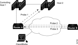
|
|