|
|

This chapter describes how to configure DLSw+, our implementation of the data-link switching (DLSw) standard for Systems Network Architecture (SNA) devices. For a complete description of the commands in this chapter, refer to the "DLSw+ Configuration Commands" chapter of the Router Products Command Reference publication.
DLSw+ is our implementation of DLSw, an SNA-over-IP routing standard that helps to integrate SNA and local-area network (LAN) internetworks by encapsulating nonroutable SNA and NetBIOS protocols within routable IP protocols. It is a means of transporting SNA and NetBIOS traffic over an Internet Protocol (IP) network. DLSw is an alternative to source-route bridging (SRB) and addresses the following limitations of SRB:
Because these limitations occur when SRB is extended across a wide-area network (WAN), DLSw is typically used to transport SNA and NetBIOS across a WAN.
The DLSw standard, documented in RFC 1795, defines the switch-to-switch protocol used between DLSw routers and defines a mechanism to locally terminate data link control connections and multiplex the traffic from the data link control connections onto a Transmission Control Protocol (TCP) connection. The standard always calls for the transport protocol to be TCP and always requires that data link control connections be locally terminated (the equivalent of our local acknowledgment option). The standard also requires that the SRB route information field (RIF) be terminated at the DLSw router. The standard describes a means for prioritization and flow control and defines error recovery procedures that assure data link control connections are appropriately disabled if any part of their associated circuits breaks.
The DLSw standard does not specify when to establish TCP connections. The capabilities exchange allows compliance to the standard but at different levels of support. The standard does not specify how to cache learned information about MAC addresses, RIFs, or NetBIOS names. It also does not describe how to keep track of both capable or preferred DLSw partners for either backup or load-balancing purposes. It does not provide the specifics of media conversion, but leaves the details up to the implementation. It does not define how to map switch congestion to data link control flow control. Finally, the management information base (MIB) is documented under a separate RFC.
DLSw+ includes the following features:
DLSw+ includes enhancements in the following areas:
DLSw+ operates in three modes:
Some enhanced DLSw+ features are also available when a Cisco router is operating in standards compliance mode with another vendor's router. In particular, enhancements that are locally controlled options on a router can be accessed even though the remote router does not have DLSw+. These include location learning (the ability to determine if a destination is on a local LAN before sending "canureach" frames across a WAN), explorer firewalls, and media conversion.
One significant factor that limits the size of Token Ring internetworks is the amount of explorer traffic that traverses the WAN. DLSw+ includes the following features to reduce the number of explorers:

The transport connection between DLSw+ routers can vary according to the needs of the network and is not necessarily tied to TCP/IP as the DLSw standard is. We support three different transport protocols between DLSw+ routers:
DLSw+ offers enhanced availability by maintaining a peer table of multiple paths to a given MAC address or NetBIOS name (where a path is either a remote peer or a local port). Each of our routers maintains a preferred path and one or more capable paths to each destination. The preferred peer is either the peer that responds first to an explorer frame or the peer with the least cost. The preferred port is always the port over which the first positive response to an explorer was received. If the preferred peer to a given destination is unavailable, the next available capable peer is promoted to the new preferred peer. No additional broadcasts are required, and recovery through an alternate peer is immediate.
Maintaining multiple paths per destination is especially attractive in SNA networks. A common technique used in the hierarchical SNA environment is assigning the same MAC address to different Token Ring interface couplers (TICs) on the IBM front-end processors (FEPs). DLSw+ ensures that duplicate TIC addresses are found, and if multiple DLSw+ peers can be used to reach the FEPs, they are all cached.
The way that multiple capable peers are handled with DLSw+ can be biased to meet either of the following network needs:
Figure 30-2 shows a peer table of preferred (Pref) and capable (Cap) routes.
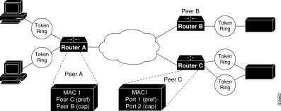
DLSw+ supports media conversion between local or remote LANs and SDLC or Ethernet. For clarity, the configuration task list below describes configuration in a Token Ring environment. The only differences for SDLC and Ethernet are the specific commands needed to configure those media, plus a media-specific command to associate the interface with DLSw+.
To configure DLSw+, perform tasks in the following sections:
See the end of this chapter for "DLSw+ Configuration Examples." Media-specific configuration examples for Ethernet and SDLC are also provided. For details of SDLC commands in the sample SDLC configuration, refer to the "LLC2 and SDLC Commands" chapter of the Router Products Command Reference publication.
The source-bridge ring can be shared between DLSw+ and SRB/RSRB. In DLSw+, the source-bridge ring group specifies the virtual ring that will appear to be the last ring in the RIF. Because RIFs are terminated at the router, there is no correlation between the ring-group number specified in DLSw+ peers. They can be the same for management simplicity, but they do not have to be. To define a source-bridge ring group for DLSw+, perform the following task in global configuration mode:
| Task | Command |
|---|---|
Define a ring group. | source-bridge ring-group ring-group1 |
| 1This command is documented in the "Source-Route Bridging Commands" chapter of the Router Products Command Reference. |
Refer to the DLSw+ Using TCP Encapsulation and LLC2 Local AcknowledgmentBasic Configuration Example for an sample configuration file.
Defining a DLSw+ local peer for a router enables DLSw+. You specify all local DLSw+ parameters as part of the local peer definition. To define a local peer, perform the following task in global configuration mode:
| Task | Command |
|---|---|
Define the DLSw+ local peer. | dlsw local-peer [peer-id ip-address] [group group] [border] [cost cost] [lf size] [keepalive seconds] [passive] [promiscuous] |
Refer to theDLSw+ Using TCP Encapsulation and LLC2 Local AcknowledgmentBasic Configuration Example for a sample configuration.
To define a ring list, perform the following task in global configuration mode:
| Task | Command |
|---|---|
Define a ring list. | dlsw ring-list list-number rings ring-number |
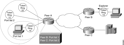
DLSw+ port lists are used to map traffic on a local interface (either Token Ring or serial) to remote peers. You can create a port list of local ports and apply the list to remote peer definitions. Traffic received from a remote peer is only forwarded to peers if the input port number appears in the port list applied to the remote peer definition. The port list command provides a single command to specify both serial and Token Ring interfaces. The definition of a port list is optional. If you want all peers and all interfaces to receive all traffic, you do not have to define a port list. Simply specify 0 for the list number in the remote peer statement.
To define a port list, perform the following task in global configuration mode:
| Task | Command |
|---|---|
Define a port list. | dlsw port-list list-number [serial | tokenring] number [serial | tokenring] number ... |
DLSw+ bridge group lists are used to map traffic on the local Ethernet bridge group interface to remote peers. You can create a bridge group list and apply the list to remote peer definitions. Traffic received from a remote peer is only forwarded to the bridge group specified in the bridge group list. Traffic received from a local interface is only forwarded to peers if the input bridge group number appears in the bridge group list applied to the remote peer definition. The definition of a bridge group list is optional. Since each remote peer has a single list number associated with it, if you want traffic to go to a bridge group and to either a ring list or port list, you should specify the same list number in each definition.
| Task | Command |
|---|---|
Define a ring list. | dlsw bgroup-list list-number bgroups number |
You can define direct, FST, or TCP encapsulation remote peers by performing one of the following tasks in global configuration mode
| Task | Command |
|---|---|
Define a direct encapsulation in HDLC for remote peer. | dlsw remote-peer list-number interface interface-name [mac-address] [cost cost] [lf size] [keepalive seconds] [lsap-output-list list] [host-netbios-out host-list-name] [bytes-netbios-out bytes-list-name] |
Define a direct encapsulation in Frame Relay for the remote peer. | dlsw remote-peer list-number frame-relay interface serial number dlci-number [pass-thru] [cost cost] [lf size] [keepalive seconds] [lsap-output-list list] [host-netbios-out host-list-name] [bytes-netbios-out bytes-list-name] |
Define an FST encapsulation remote peer. | dlsw remote-peer list-number fst ip-address [cost cost] [lf size] [keepalive seconds] [lsap-output-list list] [host-netbios-out host-list-name] [bytes-netbios-out bytes-list-name] [backup-peer ip-address] |
Define a TCP encapsulation remote peer. | dlsw remote-peer list-number tcp ip-address [priority] [cost cost] [lf size] [keepalive seconds] [tcp-queue-max size] [lsap-output-list list] [host-netbios-out host-list-name] [bytes-netbios-out bytes-list-name] [backup-peer ip-address] |
Refer to the DLSw+ Using TCP Encapsulation and LLC2 Local AcknowledgmentBasic Configuration Example for a sample configuration.
To configure peer-on-demand defaults, perform one of the following task in global configuration mode:
| Task | Command |
|---|---|
Configure FST peer-on-demand defaults. | dlsw peer-on-demand-defaults fst [bytes-netbios-out bytes-list-name] [cost cost] [host-netbios-out host-list-name] [inactivity minutes] [keepalive seconds] [lf size] [lsap-output-list list] [port-list port-list-number] |
Configure TCP peer-on-demand defaults. | dlsw peer-on-demand-defaults tcp [bytes-netbios-out bytes-list-name] [cost cost] [host-netbios-out host-list-name] [inactivity minutes] [keepalive seconds] [lf size] [local-ack] [lsap-output-list list] [priority] |
To reduce explorer traffic destined for this peer, the peer can send other peers a list of resources for which it has information (icanreach) or does not have information (icannotreach). This information is exchanged as part of a capabilities exchange.To configure static resources that will be exchanged as part of a capabilities exchange, perform one of the following tasks in global configuration mode:
| Task | Command |
|---|---|
Configure a resource not locally reachable by the router. | dlsw icannotreach saps sap [sap...] |
Configure a resource locally reachable by the router. |
To configure static paths to minimize explorer traffic originating in this peer, perform one of the following tasks in global configuration mode:
| Task | Command |
|---|---|
Configure the location or path of a static MAC address. | dlsw mac-addr mac-addr {ring-group ring | remote-peer {interface serial number | ip-address ip-address} | group group} |
Configure a static NetBIOS name. | dlsw netbios-name netbios-name {ring-group ring | remote-peer {interface serial number | ip-address ip-address}| group group} |
To configure duplicate path handling, perform the following task in global configuration mode:
| Task | Command |
|---|---|
Configure duplicate path handling. | dlsw duplicate-path-bias [load-balance] |
To enable DLSw+ on a Token Ring interface, perform the following task in interface configuration mode:
| Task | Command |
|---|---|
Enable DLSw+ on a Token Ring interface. | source-bridge local-ring bridge-number ring-group1 |
| 1This command is documented in the "Source-Route Bridging Command" chapter of the Router Products Command Reference. |
To enable DLSw+ on certain Ethernet interfaces, perform the following task in global configuration mode:
| Task | Command |
|---|---|
Enable DLSw+ on an Ethernet interface. | dlsw bridge-group bgroup-num |
To enable DLSw+ on an SDLC interface, perform the following task in interface configuration mode:
| Task | Command |
|---|---|
Enable DLSw+ on an SDLC interface. | sdlc dlsw station-address, station address ... |
To modify an existing configuration parameter, perform one or more of the following tasks in global configuration mode:
| Task | Command |
|---|---|
Disable and re-enable DLSw+ without altering the configuration. | |
Configure the depth of DLSw+ explorer queue router. | dlsw explorerq-depth queue-max |
Configure DLSw+ timers. | dlsw timer {icannotreach-block-time | netbios-cache-timeout | netbios-explorer-timeout | netbios-retry-interval | netbios-verify-interval | sna-cache-timeout | sna-explorer-timeout | sna-retry-interval | sna-verify-interval} time |
To monitor and maintain activity on the DLSw+ network, perform one or more of the following tasks in privileged EXEC mode:
| Task | Command |
|---|---|
Display capabilities of a direct-encapsulated remote peer. | show dlsw capabilities interface type | number |
Display capabilities of a TCP/FST remote peer. | show dlsw capabilities ip-address ip-address |
Display capabilities of the local peer. | show dlsw capabilities local |
Display DLSw+ circuit information. | |
Display DLSw+ peer information. | show dlsw peers |
Display DLSw+ reachability information. |
The following sections provide DLSw+ configuration examples:
This sample configuration requires the following tasks, which are described in earlier sections of this document:
Encapsulate the source-route bridged traffic inside IP datagrams passed over a TCP connection between two routers/bridges with local acknowledgment enabled when you have LANs separated by wide geographic distances and you want to avoid multiple retransmissions or loss of user sessions that can occur with time delays.
Logical Link Control-Type 2 (LLC2) is an ISO standard data link level protocol used in Token Ring networks. LLC2 was designed to ensure reliable transmission of data across LAN media with minimal or predictable time delays. With the advent of DLSw+ and WAN backbones, LANs are now separated by wide, geographic distances spanning countries and continents. As a result, these LANs have time delays that are longer than LLC2 allows for bidirectional communication between hosts. The local acknowledgment capability in routers and bridges supporting remote source-route bridging addresses the problem of unpredictable time delays, multiple retransmissions, and loss of user sessions.
In a typical LLC2 session, when one host sends a frame to another host, the sending host expects the receiving host to respond positively or negatively in a predefined period of time commonly called the T1 time. If the sending host does not receive an acknowledgment of the frame it sent within the T1 time, it retries a few times (normally 8 to 10). If there is still no response, the sending host drops the session.
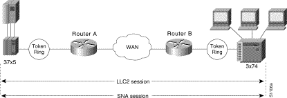
Figure 30-4 illustrates an LLC2 session. A 37x5 on a LAN segment can communicate with a 3x74 on a different LAN segment separated via a wide-area backbone network. Frames are transported between Router A and Router B by means of DLSw+. However, the LLC2 session between the 37x5 and the 3x74 is still end-to-end; that is, every frame generated by the 37x5 traverses the backbone network to the 3x74, and the 3x74, on receipt of the frame, acknowledges it.
On backbone networks consisting of slow serial links, the T1 timer on end hosts could expire before the frames have a chance to reach the remote hosts, causing the end host to retransmit. This results in duplicate frames reaching the remote host at the same time as the first frame also reached the remote host, albeit slowly. These frame duplications break the LLC2 protocol, resulting in the loss of sessions between the two IBM machines.
One way to solve this time delay problem is to increase the timeout value on the end nodes to account for the maximum transit time between the two end machines. However, in networks consisting of hundreds or even thousands of nodes, every machine would need to be reconfigured with new values. With local acknowledgment for LLC2 turned on, the LLC2 session between the two end nodes would not be end-to-end, but instead, terminate at two local routers. Figure 30-5 shows the LLC2 session with the 37x5 ending at Router A and the LLC2 session with the 3x74 ending at Router B. Both Router A and Router B execute the full LLC2 protocol as part of local acknowledgment for LLC2.

With local acknowledgment for LLC2 enabled in both routers, Router A acknowledges frames received from the 37x5. The 37x5 still recognizes the acknowledgments it receives as belonging to the 3x74. Router A looks like the 3x74 to the 37x5. Similarly, Router B acknowledges frames received from the 3x74. The 3x74 recognizes the acknowledgments it receives as coming from the 37x5. Router B looks like the 3x74 to 37x5. Because the frames no longer have to travel the WAN backbone networks to be acknowledged, but instead are locally acknowledged by routers, the end machines do not time out, resulting in no loss of sessions.
The advantages of enabling local acknowledgment for LLC2 include the following:
LLC2 local acknowledgment is enabled only with TCP remote peers (as opposed to LAN or direct serial interface remote peers).
If the LLC2 session between the local host and the router terminates in either router, the other will be informed to terminate its connection to its local host.
If the TCP queue length of the connection between the two routers reaches the highwater mark, the routers sends Receiver-Not-Ready (RNR) messages to the local hosts until the queue limit is reduced to below this limit.
The configuration of the LLC2 parameters for the local Token Ring interfaces can affect overall performance. Refer to the chapter "Configuring LLC2 and SDLC Parameters" in this manual for more details about fine-tuning your network through the LLC2 parameters.
The routers at each end of the LLC2 session execute the full LLC2 protocol, which could result in some overhead. The decision to use local acknowledgment for LLC2 should be based on the speed of the backbone network in relation to the Token Ring speed. For LAN segments separated by slow-speed serial links (for example, 56 kbps), the T1 timer problem could occur more frequently. In such cases, it might be wise to turn on local acknowledgment for LLC2. For LAN segments separated by a T1, backbone delays will be minimal; in such cases, FST or direct should be used. Speed mismatch between the LAN segments and the backbone network is one criterion to help you decide to use local acknowledgment for LLC2.
There are some situations (such as the receiving host failing between the time the sending host sends data and the time the receiving host receives it), in which the sending host would determine, at the LLC2 layer, that data was received when it actually was not. This error occurs because the router acknowledges that it received data from the sending host before it determines that the receiving host can actually receive the data. But because both NetBIOS and SNA have error recovery in situations where an end device goes down, these higher-level protocols will resend any missing or lost data. Because these transaction request/confirmation protocols exist above LLC2, they are not affected by tight timers, as is LLC2. They also are transparent to local acknowledgment.
If you are using NetBIOS applications, note that there are two NetBIOS timers—one at the link level and one at the next higher level. Local acknowledgment for LLC2 is designed to solve link timeouts only. If you are experiencing NetBIOS session timeouts, you have two options:
Figure 30-6 illustrates a DLSw+ configuration with local acknowledgment.

source-bridge ring-group 10
!
dlsw local-peer peer-id 10.2.25.1
dlsw remote-peer 0 tcp 10.2.5.2
int loopback 0
ip address 10.2.25.1 255.255.255.0
.
.
.
interface TokenRing 0
no ip address
ring-speed 16
source-bridge active 25 1 10
source-bridge ring-group 12
dlsw local-peer peer-id 10.2.5.2
dlsw remote-peer 0 tcp 10.2.25.1
int loopback 0
ip address 10.2.5.2 255.255.255.0
.
.
.
interface TokenRing 0
no ip address
ring-speed 16
source-bridge active 5 1 12
Figure 30-7 illustrates DLSw+ configured using border peers, showing circuits to each other. Router A is configured to operate in promiscuous mode, and border peers Routers B and C forward broadcasts. This configuration reduces processing requirements in router A (the access router) and still support any-to-any networks.
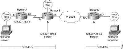
The following are configuration files for the routers in Figure 30-7.
hostname RouterA
!
source-bridge ring group 31
dlsw local-peer peer-id 128.207.152.5 group 70 promiscuous
dlsw remote peer 0 tcp 128.207.150.8
!
interface Serial0
ip unnumbered TokenRing
clockrate 56000
!
interface TokenRing 0
ip address 128.207.152.5 255.255.255.0
ring-speed 16
source-bridge 200 13 31
source-bridge spanning
!
.
.
.
router igrp 777
network 128.207.0.0
hostname RouterB
!
.
.
.
source-bridge ring-group 31
dlsw local-peer peer-id 128.207.150.8 group 70 border promiscuous
dlsw remote-peer 0 tcp 128.207.169.3
dlsw remote-peer 0 tcp 128.207.152.5
!
.
.
.
interface serial0
ip unnumbered tokenring 0
bandwidth 56
!
.
.
.
interface tokenring 0
ip address 128.207.150.8 255.255.255.0
ring-speed 16
source-bridge 3 14 31
source-bridge spanning
!
router igrp 777
network 128.207.0.0
hostname RouterC
!
.
.
.
source-bridge ring-group 69
dlsw local-peer peer-id 128.207.169.3 group 69 border promiscuous
dlsw remote-peer 0 tcp 128.207.150.8
!
.
.
.
interface tokenring 3/0
description fixed to flashnet
ip address 128.207.2.152 255.255.255.0
ring-speed 16
multiring all
!
interface tokenring 3/1
ip address 128.207.169.3 255.255.255.0
ring-speed 16
source-bridge 33 2 69
source-bridge spanning
!
.
.
.
router igrp 777
network 128.207.0.0
Figure 30-8 illustrates a peer group configuration that allows any-to any connection except for Router B.
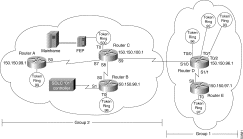
The following are configuration files for the routers in Figure 30-8:
hostname Router A
!
.
.
.
source-bridge ring-group 2000
dlsw local-peer peer-id 150.150.99.1
dlsw remote-peer 0 tcp 150.150.100.1
!
interface loopback 0
 ip address 150.150.99.1 255.255.255.192
!
interface serial 0
 ip address 150.150.9.1 255.255.255.192
!
.
.
.
interface tokenring 0
 no ip address
 ring-speed 16
 source-bridge 99 1 2000
 source-bridge spanning
!
.
.
.
router eigrp 202
 network 150.150.0.0
hostname RouterB
!
.
.
.
source-bridge ring-group 2000
dlsw local-peer peer-id 150.150.98.1 group 2
dlsw remote-peer 0 tcp 150.150.100.1
!
interface loopback 0
 ip address 150.150.98.1 255.255.255.192
!
.
.
.
interface serial 1
 no ip address
 encapsulation sdlc
 no keepalive
 priority-group 1
 clockrate 9600
 sdlc role primary
 sdlc vmac 4000.8888.0100
 sdlc address 01
 sdlc xid 01 05d20006
 sdlc partner 4000.1020.1000 01
 sdlc dlsw 1
!
interface tokenring 0
 no ip address
 ring-speed 16
 multiring all
 source-bridge 98 1 2000
 source-bridge spanning
!
.
.
.
router eigrp 202
 network 150.150.0.0
hostname RouterC
!
.
.
.
source-bridge ring-group 2000
dlsw local-peer peer-id 150.150.100.1 group 2 border promiscuous
dlsw remote-peer 0 tcp 150.150.96.1
dlsw remote-peer 0 tcp 150.150.98.1
dlsw remote-peer 0 tcp 150.150.99.1
!
interface loopback 0
 ip address 150.150.100.1 255.255.255.192
!
.
.
.
interface serial 7
 ip address 150.150.9.2 255.255.255.192
 clockrate 56000
!
interface serial 8
 ip address 150.150.10.2 255.255.255.192
!
interface serial 9
 ip address 150.150.8.2 255.255.255.192
!
interface tokenring 0
 no ip address
 ring-speed 16
 multiring all
 source-bridge 500 1 2000
!
router eigrp 202
 network 150.150.0.0
hostname RouterD
!
.
.
.
source-bridge ring-group 2000
dlsw local-peer peer-id 150.150.96.1 group 1 border
dlsw remote-peer 0 tcp 150.150.97.1
dlsw remote-peer 0 tcp 150.150.100.1
!
interface loopback 0
 ip address 150.150.96.1 255.255.255.192
!
.
.
.
interface serial 1/0
 ip address 150.150.8.1 255.255.255.192
 clockrate 56000
!
interface serial 1/1
 ip address 150.150.16.1 255.255.255.192
!
.
.
.
interface tokenrin g0/0
 ip address 150.150.2.1 255.255.255.192
 ring-speed 16
 source-bridge 96 1 2000
 source-bridge spanning
!
interface tokenring 0/1
 ip address 150.150.13.1 255.255.255.192
 no ip address
 ring-speed 16
 source-bridge 92 1 2000
 source-bridge spanning
!
.
.
.
router eigrp 202
 network 150.150.0.0
hostname RouterE
!
.
.
.
source-bridge ring-group 2000
dlsw local-peer peer-id 150.150.97.1 group 1 promiscuous
dlsw remote-peer 0 tcp 150.150.96.1
!
interface loopback 0
 ip address 150.150.97.1 255.255.255.192
!
interface serial 0
 mtu 1400
 ip address 150.150.16.2 255.255.255.192
!
.
.
.
interface tokenring 0
 no ip address
 no ip route-cache
 ring-speed 16
 source-bridge 97 1 2000
 source-bridge spanning
!
.
.
.
router eigrp 202
 network 150.150.0.0
DLSw+ also supports Ethernet media. Except for configuring for a specific media, in this case Ethernet, the configuration is similar to other DLSw+ configuration.

The following are the configuration files for the routers in figure 26-9.
hostname RouterA
!
.
.
.
source-bridge ring-group 31
dlsw local-peer peer-id 128.207.2.155
dlsw remote-peer 0 tcp 128.207.1.145 lf 1500
dlsw bridge-group 5
!
interface Ethernet 0
 ip address 128.207.111.1 255.255.255.0
 bridge-group 5
!
.
.
bridge 5 protocol ieee
!
.
.
hostname RouterB
!
.
.
.
source-bridge ring-group 500
dlsw local-peer peer-id 128.207.1.145
dlsw remote-peer 0 tcp 128.207.2.155 lf 1500
 dlsw bridge-group 5
.
.
.
interface ethernet 1/2
 ip address 128.207.1.145 255.255.255.0
 bridge-group 5

.
.
.
interface tokenring 2/0
 no ip address
 ring-speed 16
 multiring all
 source-bridge 7 1 500
 source-bridge spanning
!
.
.
.
router igrp 777
 network 128.207.0.0
DLSw+ provides media conversion between local or remote LANs and SDLC. For additional information about configuring SDLC parameters, refer to the chapter "Configuring LLC2 and SDLC Parameters."
Figure 30-10 illustrates DLSw+ with SDLC encapsulation. For this example, 4000.1020.1000 is the MAC address of the FEP host (PU4). 1000.5aed.1f53 is the MAC address of the AS/400 host, which is defined as Node Type 2.1. Router B serves as the primary station for the remote secondary stations 01. Router B can serve as either primary station or secondary station to remote station D2.
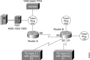
The following is the configuration file for Router A:
hostname RouterA
!
.
.
.
source-bridge ring-group 2000
dlsw local-peer peer-ed 150.150.10.2
dlsw remote-peer 0 tcp 150.150.10.1
!
.
.
.
interface serial 8
 ip address 150.150.10.2 255.255.255.192
 clockrate 56000
!
.
.
.
interface tokenring 0
 no ip address
 ring-speed 16
 source-bridge 500 1 2000
source-bridge spanning
!
.
.
.
router eigrp 202
 network 150.150.0.0
hostname RouterB
!
.
.
.
source-bridge ring-group 2000
dlsw local-peer peer-id 150.150.10.1
dlsw remote-peer 0 tcp 150.150.10.2
!
.
.
.
interface serial 0
 ip address 150.150.10.1 255.255.255.192
!
interface serial 1
 description PU2 with SDLC station role set to secondary
 no ip address
 encapsulation sdlc
 no keepalive
 clockrate 9600
 sdlc role primary
 sdlc vmac 4000.9999.0100
 sdlc address 01
 sdlc xid 01 05d20006
 sdlc partner 4000.1020.1000 01
sdlc dlsw 1
!
interface serial 2
 description Node Type 2.1 with SDLC station role set to negotiable or primary
 encapsulation sdlc
 sdlc role none
 sdlc vmac 1234.3174.0000
 sdlc address d2
 sdlc partner 1000.5aed.1f53 d2
 sdlc dlsw d2
!
interface tokenring 0
 no ip address
 early-token-release
 ring-speed 16
 multiring all
 source-bridge 100 1 2000
 source-bridge spanning
!
interface tokenring 1
 no ip address
 ring-speed 16
 multiring all
 source-bridge 400 1 2000
 source-bridge spanning
!
router eigrp 202
 network 150.150.0.0\
![]()
![]()
![]()
![]()
![]()
![]()
![]()
![]()
Posted: Wed Oct 16 10:16:54 PDT 2002
All contents are Copyright © 1992--2002 Cisco Systems, Inc. All rights reserved.
Important Notices and Privacy Statement.