|
|

This chapter describes how to configure protocol translation sessions. It assumes you understand how to use the IOS software. It provides procedures for specifying system-wide facilities, as well as application examples. Before continuing with this chapter, be sure that you are familiar with the information provided in the Local Area Transport (LAT), TN3270, Serial Line Internet Protocol (SLIP) and Point-to-Point Protocol (PPP), and XRemote configuration chapters in this publication. For information about X.25 and Transmission Control Protocol/Internet Protocol (TCP/IP, which includes TCP, SLIP and PPP, and Telnet), refer to the Router Products Configuration Guide and the Router Products Command Reference publications.
For a complete description of the commands in this chapter, see the "Protocol Translation Session Commands" chapter later in this publication. For information about making connections and establishing translation sessions, see the Cisco Access Connection Guide.
The IOS software attempts to provide transparent protocol translation between systems running disparate protocols. The software fully supports two-way virtual terminal protocol translation between nodes running X.25, LAT, SLIP or Point-to-Point Protocol (PPP), and Telnet.
The IOS software supports limited translation for XRemote (to X.25 PAD environments) and TN3270 (to LAT, X.25, and Telnet environments). However, there is no translation between other services such as file-transfer protocols. The protocol translation software allows terminal users on one network to access hosts on another network, despite differences in the native protocol stacks associated with the originating device and the target host. You can use either of two methods to accomplish this:
A router running protocol translation uses the International Telecommunication Union Telecommunication Standardization Sector (ITU-T) Recommendation X.25 for transferring raw data over X.25 networks. The X.25 software supports both commercial and defense data network (DDN) versions. Such a router also supports X.25 as a transport mechanism for IP packets, and X.3- and X.29-based PAD connections. This allows the routers with protocol translation to connect to an X.25 public data network (PDN). This X.25 connection allows transport of TCP/IP packets across the X.25 packet-switching network in the same way as would occur on a standalone protocol translator.
Routers without protocol translation software do not support an X.25 PAD function, so they cannot communicate with hosts directly connected to the X.25 PDN. Routers with protocol translation encapsulate TCP/IP packets in X.25 packets for transfer over a packet-switching network. These packets can be received by another router configured with protocol translation software. Only protocol translation software includes PAD capabilities, but other internetworking devices can communicate with routers running such software using the TCP/IP or LAT protocols. Protocol translation software can translate TCP/IP and LAT into X.25, and then communicate with X.25 hosts. Protocol translation software supports all PAD standards (X.28, X.29, and X.3). The connection to the packet-switching network is through a synchronous line.
Connections to a PAD are made using EXEC commands. You can configure PAD parameter profiles that can be used to set PAD parameters with other commands, and you can configure access lists to control X.25 network access. Both these features use the message fields defined in Recommendation X.29, which describes procedures for exchanging data between PADs or between a PAD and a DTE.
Perform the tasks in the following sections, as appropriate, when setting up protocol translation:
Perform the tasks in the following sections to apply X.29 PAD connections under X.25:
See the section "Protocol Translation Session Configuration Examples" at the end of this chapter for protocol translation application examples.
If you want to translate SLIP or PPP (on outgoing connections only) using the two-step protocol translation method, you first need to enable asynchronous protocol functions on all virtual terminal lines that have been created for the router.
SLIP and PPP function only on asynchronous interfaces, or on virtual terminal lines set up for asynchronous protocol functions. A virtual terminal line set up for asynchronous protocol functions is called a virtual asynchronous interface. For more information about virtual asynchronous interfaces, refer to the "Configuring SLIP and PPP" chapter in this publication.
Enabling SLIP and PPP on virtual asynchronous interfaces permits you to run SLIP and PPP in an X.25 PAD environment, thus extending remote node capability into the X.25 area. You can also run SLIP and PPP in a Telnet or LAT environment.
To translate from X.25, LAT, or Telnet to SLIP or PPP using the one-step method, you do not need to enter any special commands. Simply use the translate command with the SLIP or PPP keywords for one-step connections. The translate command automatically enables asynchronous protocol functions on one virtual terminal line at a time.
To create a virtual asynchronous interface to enable translation of SLIP and PPP, perform the following task in global configuration mode:
| Task | Command |
|---|---|
Create a virtual asynchronous interface for translating SLIP and PPP. | vty-async1 |
| 1This command is described in the "SLIP and PPP Configuration Commands" chapter in this publication. |
For more information about configuring virtual asynchronous interfaces, refer to the "Configuring SLIP and PPP" chapter.
To configure the two-step method of protocol translation, see the configuration task list in the Cisco Access Connection Guide.
One disadvantage of using the one-step method is that the initiating computer or user does not know that two networking protocols are being used. This means that parameters of the foreign network protocols cannot be changed once the connections are established. The exception to this limitation is the set of parameters common to both networking protocols. Any parameter in this set can be changed from the first host to the final destination.
To configure the one-step method of protocol translation, set up the following protocols and connection options in the configuration file:
To perform one-step protocol translation of LAT, X.25, Telnet, or SLIP/PPP, enter the following command in global configuration mode:
| Task | Command |
|---|---|
Configure protocol translation. | translate protocol incoming-address [in-options] protocol outgoing-address [out-options] [global-options] |
SLIP and PPP can only be translated on outgoing connections.
For examples of using the one-step method, see the section "Protocol Translation Session Configuration Examples" later in this chapter.
In the two-step method, perform the following two steps:
Step 1 Establish the incoming connection directly to the router running protocol translation software.
Step 2 Establish the outgoing connection from the router running protocol translation software to another network host.
Specifically, once the transmission protocols—LAT, X.25, TCP/IP, SLIP, or PPP—are configured, all that is required for the two-step protocol translation method is to enter the EXEC connection
commands—lat, pad, telnet, slip, ppp—first to the router, then to the outgoing device.
Protocol translation software supports the two-step method in both directions (for example, from Telnet to PAD, and vice versa).
In general, you use the two-step method when you want to use a router running protocol translation software as a general-purpose gateway between two types of networks (for example, X.25 PDN and TCP/IP). Instead of configuring every possible connection via embedded translate commands, the two-step method allows you greater flexibility in terms of connecting to network resources accessible via the router running protocol translation software.
The two-step method also allows additional security when TACACS and password protection is enabled. These security features are described in Router Products Configuration Guide, in the chapter "Managing the System." Additionally, if you use the two-step method to connect, you can change X.25 PAD and local terminal parameters dynamically during a session.
With the two-step connection method, you can individually modify the parameters of either network connection, even while a session is in process. This process is similar to connecting a group of terminal lines from a PAD to a group of terminal lines from a router running protocol translation software. The difference is that you do not encounter the wiring complexity, unreliability, management problems, and performance bottlenecks that occur when two separate devices are connected via asynchronous serial lines.
The number of protocol translation sessions supported by the IOS Release 10.3 software depends on the router model. On a Cisco 4000 or Cisco 4500, the maximum number of protocol translation sessions is 180 whether or not routing is enabled. On a Cisco 2500 or Cisco 3000, the maximum number of protocol translation sessions is 100 sessions, or 32 sessions if routing is enabled.
The number of protocol translation sessions is tied to the number of virtual terminal lines set up on the router running protocol translation software. That is, if such a router has ten virtual terminal lines, you can have up to ten protocol translation sessions. The default number of virtual terminal lines is five (lines 0 through 4). To increase the number of lines, and thus the maximum number of protocol translation sessions, perform the following task in line configuration mode:
| Task | Command |
|---|---|
Increase the number of virtual terminal lines, and thus, the maximum number of protocol translation sessions. | line vty number1 |
Decrease the number of virtual terminal lines, and thus, the maximum number of protocol translation sessions. | no line vty number |
| 1This command is documented in the "Terminal Lines and Modem Support Commands" chapter in the Router Products Command Reference publication. |
The protocol translation software provides access lists, which make it possible to limit access to a router running protocol translation software from certain X.25 hosts. Access lists take advantage of the message field defined by Recommendation X.29, which describes procedures for exchanging data between two PADs or between a PAD and a DTE device.
To define X.29 access lists, perform the following tasks:
Step 1 Create an access list.
Step 2 Apply an access list to a virtual line or include it in a translate command.
These tasks are described in the following sections.
When configuring protocol translation, you can specify an access-list number with each translate command. In the case of translation sessions that result from incoming PAD connections, the corresponding X.29 access list is used.
To specify the access conditions, perform the following global configuration task:
| Task | Command |
|---|---|
Restrict incoming and outgoing connections between a particular virtual terminal line (into a Cisco device) and the addresses in an access list. | x29 access-list access-list-number {permit | deny} regular-expression |
An access list can contain any number of lines. The lists are processed in the order in which you type the entries. The first match causes the permit or deny condition. If an X.121 address does not match any of the entries in the access list, access will be denied.
To apply an access list to a virtual line, perform the following tasks in line configuration mode:
| Task | Command |
|---|---|
Restrict incoming and outgoing connections between a particular virtual terminal line (into a Cisco device) and the addresses in an access list. |
| 1This command is documented in the "LAT Configuration Commands" chapter. |
The access-list number is used both for incoming TCP access and for incoming PAD access. For TCP access, the router running protocol translation software uses the defined IP access lists. For incoming PAD connections, the same X.29 access list is used. If you want to have access restrictions on only one of the protocols, you can create an access list that permits all addresses for the other protocol.
You can create an X.29 profile script for use by the translate command. When an X.25 connection is established, the router running protocol translation software then acts as if an X.29 SET PARAMETER packet had been sent that contained the parameters and values set by this command.
To create an X.29 profile script, perform the following global configuration task:
| Task | Command |
|---|---|
Create an X.29 profile script. |
To define symbolic host names, perform the following task in global configuration mode:
| Task | Command |
|---|---|
Define a symbolic host name. |
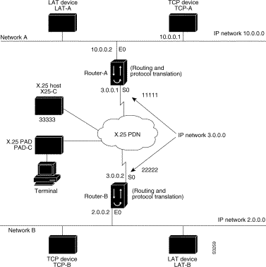
The following sections present examples of configuring protocol translation sessions. The environment used in these examples is illustrated in Figure 6-1.
In these examples, a LAT device can be a LAT terminal server or LAT host, and a TCP device can be either a TCP terminal server or TCP host.
The following examples illustrate the basic global configuration commands and interface configuration commands for setting up Router-A (connected to Network A) and Router-B (connected to Network B), as illustrated in Figure 6-1. Refer to the chapter "Configuring LAT," earlier in this publication, for more information about LAT. For information on configuring X.25, refer to the Router Products Configuration Guide.
interface ethernet 0
ip address 1.0.0.2 255.255.0.0
!
! Enable LAT on interface
lat enabled
!
interface serial 0
encapsulation X.25
x25 address 11111
!
! The following parameters may depend on your network
x25 facility packetsize 512 512
x25 facility windowsize 7 7
!
! IP address and MAP command needed only if routing IP
ip address 3.0.0.1 255.255.0.0
x25 map ip 3.0.0.2 22222 broadcast
!
! Set up IP routing
router igrp 100
network 1.0.0.0
network 3.0.0.0
!
! Advertise as available for connections via LAT
! Use this name (Router-A) if connecting via 2-step method
! (for connecting directly to a specific router)
lat service Router-A enable
!
! Set up some IP host names/addresses
ip host Router-A 1.0.0.2 3.0.0.1
ip host TCP-A 1.0.0.1
ip host TCP-B 2.0.0.1
ip host Router-B 3.0.0.2 2.0.0.2
interface ethernet 0
ip address 2.0.0.2 255.255.0.0
!
! enable LAT on interface
lat enabled
!
interface serial 0
encapsulation X.25
x25 address 22222
! The following parameters may depend on your network
x25 facility packetsize 512 512
x25 facility windowsize 7 7
!
! IP address and MAP command needed only if routing IP
ip address 3.0.0.2 255.255.0.0
x25 map ip 3.0.0.2 11111 broadcast
!
! Set up IP routing
router igrp 100
network 2.0.0.0
network 3.0.0.0
!
! advertise as available for connections via LAT
! Use this name (Router-B) if connecting via 2-step method
! (for connecting directly to a specific Router)
lat service Router-B enable
!
! Set up some IP host names/addresses
ip host Router-A 3.0.0.1 1.0.0.2
ip host TCP-A 1.0.0.1
ip host TCP-B 2.0.0.1
ip host Router-B 2.0.0.2 3.0.0.2
The following example sets the number of protocol translation sessions to 120, whether routing is turned on or off:
line vty 119
The following example sets the number of protocol translation sessions to 10, whether routing is turned on or off:
no line vty 10
A router running protocol translation software can translate between LAT and Telnet traffic to allow communication among resources in these protocol environments. In Figure 6-2, the LAT device on Network A (LAT-A) is shown connecting to a device running Telnet (TCP-A).
This is only a partial example. The commands in this example are only part of the complete configuration file for an individual device.
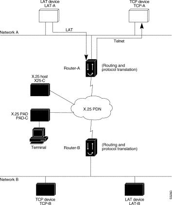
The following example configures device Router-A to translate from LAT to TCP:
! Translate LAT connections to TCP for connectivity to TCP-A
translate lat TCP-A tcp TCP-A
! Optional additional commands
lat service TCP-A ident Protocol Translation to TCP-A
In the last command, the text string "Protocol Translation to TCP-A" is an identification string for the LAT service named TCP-A. This string is sent to other servers on the local network.
A router running protocol translation software can translate between X.25 and PPP traffic to allow communication among resources in these protocol environments. In Figure 6-3, the PC establishes a SLIP or PPP session with the router through an X.25 network using CHAP authentication. The router then establishes a connection to IP host and passes traffic from the PC running SLIP or PPP to IP host.
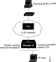
The following configuration tunnels PPP inside X.25 packets from the PPP client to the virtual asynchronous interface with IP address 1.0.0.4. Routing and CHAP authentication are enabled for the PPP session. With the router connected to IP host, the PC running SLIP or PPP can now communicate with the IP host.
translate x25 31370054065 ppp 1.0.0.4 routing authentication chap
This is only a partial example. The commands in this example would be only part of the complete configuration file for an individual device.
A router running protocol translation software can translate between TCP and SLIP traffic to allow communication among resources in these protocol environments. In Figure 6-3, the PC running SLIP is connecting to a TCP/IP network and making a connection with the device IP host. This example enables routing and turns on header compression.

The following configuration tunnels SLIP inside of TCP packets from the SLIP client with IP address 2.0.0.5 to the router. The router then establishes a protocol translation session to IP host. Routing and header compression are enabled for the SLIP session.
translate tcp 1.0.0.1 slip 2.0.0.5 routing header-compression passive
The device IP host on a different network attached to the router can be accessed by the SLIP client because routing has been enabled on the interface in the router where the SLIP session is established.
This is only a partial example. The commands in this example would be only part of the complete configuration file for an individual device.
Protocol translation permits LAT devices to communicate with X.25 hosts through an X.25 PDN. In the application illustrated in Figure 6-5, LAT-A is a LAT device that is communicating with X25-C, an X.25 host. The LAT traffic from LAT-A is translated to X.25.
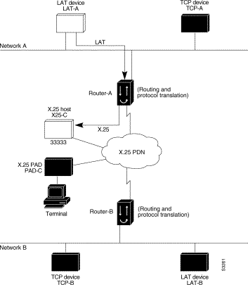
The following example illustrates how to use the translate global configuration command to translate from LAT to X.25. It is applied to Router-A. This example sets up reverse charging for connections, which causes the router running protocol translation software to instruct the PDN to charge the destination for the connection. It is essentially a collect call. The reversal of charges must be pre-arranged with the PDN and destination location (on an administrative basis), or the call will not be accepted.
! Translate LAT to X.25 host, with reverse charging
translate lat X25-C x25 33333 reverse
!
! Specify optional X.25 hostname
x25 host X25-C 33333
Protocol translation permits terminals connected to X.25 PADs to communicate with LAT devices on a remote LAN (Figure 6-6). X.25 PAD terminals make a call using an X.121 address, which is translated to a LAT node. To the PAD terminal user, the connection appears to be a direct connection to a host on the X.25 PDN. The router also supports X.29 access lists, which allow you to restrict LAN resources (LAT or TCP) available to the PAD user.
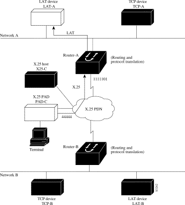
The following example illustrates how to use the translate global configuration command to translate from an X.25 PAD to a LAT device on Network A. It is applied to Router-A. The configuration example includes an access list that limits remote LAT access through Router-A to connections from PAD-C.
! Define X25 access list to only allow pad-c
x29 access-list 1 permit ^44444
x29 access-list 1 deny .*
!
! Set up translation
translate x25 1111101 lat LAT-A access-class 1
This configuration example typifies the use of access lists in the IOS software. The first two lines define the scope of access-list 1. The first line specifies that access list 1 will permit all calls from X.121 address 44444. The caret symbol (^) specifies that the first number 4 is the beginning of the address number. Refer to the appendix "Regular Expressions" later in this publication for details concerning the use of special characters in defining X.121 addresses. The second line of the definition explicitly denies calls from any other number.
This access list is then applied to all incoming traffic on the serial port for Router-A (X.121 address 1111101) with the third configuration line in the example. However, it applies only to the translate command at the end of this example. This translate command specifies that incoming X.25 packets on the serial line (with address 1111101) are translated to LAT and sent to LAT-A if they pass the restrictions of the access list.
If you define multiple X.25 translate commands, each must contain a unique X.121 address. It is also important that the ITU-T protocol used in transferring packets match among X.121 addresses. This is specified in the protocol identification field of call-user data. This field specifies whether a packet is routed, translated, or handled as a virtual terminal connection.
Making a translated connection from an X.25 PAD to a TCP device (Figure 6-7) is analogous to the preceding X.25 PAD-to-LAT example. Instead of translating to LAT, the Router-A configuration includes a statement to translate to TCP (Telnet). Note that a router running protocol translation software can include statements supporting both translations (X.25 PAD-to-LAT and X.25 PAD-to-TCP). Different users on the same PAD can talk to X.25, LAT, or TCP devices.
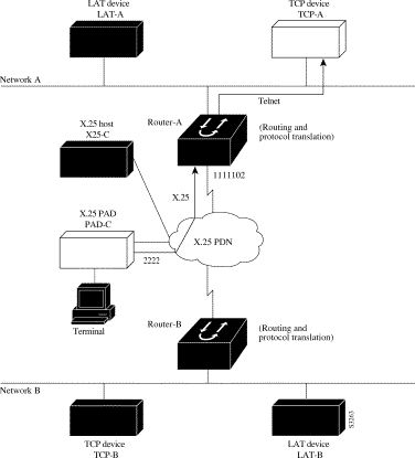
The following example illustrates how to use the translate global configuration command to translate from an X.25 PAD to a TCP device on Network A. It is applied to Router-A.
! Set up translation
translate x25 2222 tcp TCP-A
The protocol translation software provides transparent connectivity between LAT devices on different networks via an X.25 PDN. In Figure 6-8, which illustrates this application, the LAT device on Network A (LAT-A) first makes a virtual connection to Router-A on Network A using the LAT protocol. Router-A then translates the LAT packets into X.25 packets and sends them through the X.25 network to Router-B on Network B. Router-B translates the X.25 packets back to LAT packets and establishes a virtual connection to the LAT device on Network B (LAT-B). These handoffs are handled transparently when the protocol translation software is configured for a one-step translation.

The following two examples illustrate how to use the translate global configuration command to translate from LAT to X.25 and from X.25 back to LAT to allow connection service to a LAT device on Network B from a LAT device on Network A. This requires two separate configurations, one for each LAT device.
! Translate LAT to X.25 on Router-A, which is on Network A
translate lat DISTANT-LAT x25 2222201

! Translate X.25 to LAT on Router-B, which is on Network B
translate x25 2222201 lat LAT-B
In the first translate command, DISTANT-LAT defines a LAT service name for Router-A. When a user on device LAT-A attempts to connect to TCP-B, the target specified in the connect command is DISTANT-LAT. (The connect command is described in the Cisco Access Connection Guide.)
In the translate command for Router-B, the name of the LAT service on the target host (LAT-B) is LAT-B. Router-B translates the incoming X.25 packets from 2222201 to LAT and then transparently relays these packets to LAT-B.
The following is an example of a connection request. In this configuration example, when the user enters this command, a connection attempt from LAT-A on Network A to TCP-B on Network B is attempted.
local> connect DISTANT-LAT
To configure Router-B to send information back from LAT-B to LAT-A, use commands symmetrical to the prior configuration (this path is not shown in Figure 6-8):
! Translate LAT to X.25 on Router-B, which is on Network B
translate lat FAR-LAT x25 1111103

! Translate X.25 to LAT on Router-A, which is on Network A
translate x25 1111103 lat LAT-A
You can use protocol translation software to provide transparent connectivity between LAT and TCP devices on different networks via an X.25 PDN. In the application illustrated in Figure 6-9, the LAT device on Network A is communicating with the TCP device on Network B. There are two ways to provide this connectivity: the LAT traffic from Network A can be translated into either X.25 packets or TCP/IP packets to be sent out on the X.25 PDN.
If the traffic is translated from LAT directly into X.25 frames by Router-A, then Router-B on Network B translates incoming packets intended for device TCP-B into TCP. If Router-A converts LAT to TCP, then the TCP traffic is being encapsulated in X.25 and sent on the X.25 network; Router-B on Network B strips off the encapsulation and routes the TCP packet. In this case, protocol translation is not needed on Router-B.
If the traffic is translated to TCP by Router-A, the packets are encapsulated within X.25 frames. In general, translating the traffic directly to X.25 is more efficient in this application because no encapsulation is necessary. X.25 packets have only 5 bytes of header information, while TCP over X.25 has 45 bytes of header information.

The following examples illustrate how to use the translate global configuration command to translate from LAT to X.25 (on Router-A) and from X.25 to TCP (on Router-B), thus allowing connection service to a TCP device on Network B (TCP-B) from a LAT device on Network A (LAT-A). You must configure Router-A and Router-B separately.
! Translate LAT to X.25 on Router-A, which is on Network A
translate lat DISTANT-TCP x25 2222202

! Translate X.25 to TCP on Router-B, which is on Network B
translate x25 2222202 tcp TCP-B
In the translate command for Router-A, DISTANT-TCP defines a LAT service name for Router-A. When a user on device LAT-A attempts to connect to LAT-B, the target specified in the connect command is DISTANT-TCP.
In the translate command for Router-B, the TCP service on the target host (TCP-B) is TCP-B. Router-B translates the incoming X.25 packets from 2222202 to TCP packets and transparently relays these packets to TCP-B.
The following is an example of a connection request. In this configuration example, when the user enters this command, a connection attempt from LAT-A on Network A to LAT-B on Network B is attempted.
local> connect DISTANT-TCP
To transport LAT traffic over a Frame Relay or an SMDS network, LAT must first be translated to TCP. The TCP traffic is routed over the Frame Relay network and then translated back to LAT on Router-B on Network B. See Figure 6-10.
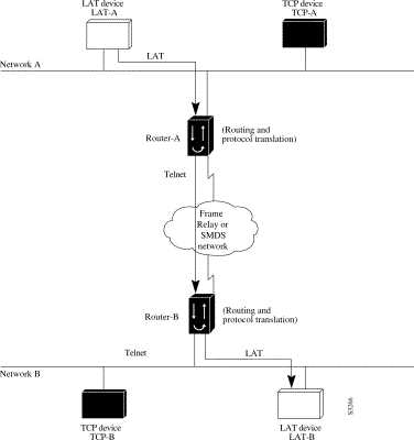
The following example illustrates how to use translate global configuration command to translate from LAT to LAT when the WAN uses Frame Relay or SMDS. In this configuration, the router routes encapsulated packets translated from LAT to TCP over the Frame Relay or SMDS network. Packets are then translated back to LAT on the other side of the Frame Relay or SMDS network.
! Translate LAT to TCP/Telnet on Router-A, which is on Network A
translate lat DISTANT-LAT tcp Router-A

! Translate TCP to LAT on Router-B, which is on Network B
translate tcp Router-B lat LAT-B
The protocol translation software can be used to connect LAT devices over a WAN backbone that only allows routable protocols (see Figure 6-11). This configuration exists when LAT networks are either isolated or on their own internetwork.
With the protocol translation software, LAT traffic can be translated to TCP and then routed on the WAN as TCP traffic. The LAT connections stay local between the LAT device and the router running protocol translation software. Thus, connections are not susceptible to delays on the WAN. This reduces the amount of traffic on the WAN because only the data from specific LAT sessions is forwarded on the WAN rather than all the LAT protocol status information packets.
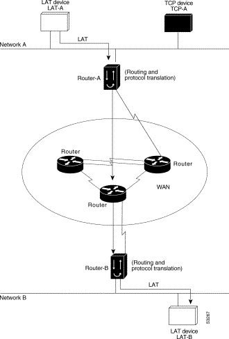
The following example illustrates how to use the translate global configuration command to translate from LAT to LAT when an IP WAN is used. In this configuration, the router running protocol translation software routes encapsulated packets translated from LAT to TCP over the WAN. Packets are then translated back to LAT on the other side of the WAN. Example translation configurations for both Router-A and Router-B are shown, but these examples do not include specifics of configuration for devices in the WAN. These examples are essentially the same configurations for protocol translation as those in the earlier Frame Relay example.
! Translate LAT to TCP/Telnet for Router-A, which is on Network A
translate lat DISTANT-LAT tcp Router-A

! Translate TCP to LAT for Router-B, which is on Network B
translate tcp Router-B lat LAT-B
To support this application, a router running protocol translation software is directly connected back-to-back (Figure 6-12) to another Cisco device. This second device acts as an X.25 switch, by sending X.25 packets to Router-B while concurrently routing and bridging other protocols.
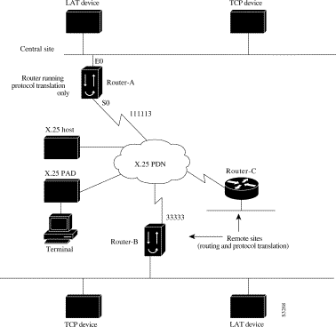
The following example illustrates how to configure a device to support translating protocols over an X.25 network among multiple sites.
Router-C is configured to act as an X.25 switch to send X.25 packets to Router-A while concurrently routing and bridging other protocols.
The following example also illustrates how to use the translate global configuration command to translate LAT and TCP over X.25 WAN media. In this configuration, Router-A can translate LAT or TCP traffic into X.25 packets for transmission over an X.25 PDN network. Packets are then translated back to LAT or TCP on the other side of the WAN.
interface ethernet 0
ip address 1.0.0.2 255.255.0.0
!
! enable LAT on interface if concurrently routing (8.3 feature)
lat enable
!
interface serial 0
encapsulation X.25
! note that this is subaddress 3 of 11111
x25 address 111113
! The following parameters may depend on your network
x25 facility packetsize 512 512
x25 facility windowsize 7 7
no ip address

! "Other" Central Site Cisco Router Configuration
!
! Interface to WAN
interface serial 0
x25 address 11111
x25 route ^111113 interface serial 1
ip address ....
! Interface to Router-A
interface serial 1
x25 route .* interface serial 0
no ip address

! Translate Configuration for Router-A
!
no ip routing
! Note subaddress of subaddress 11111(3(3))
translate x25 1111133 tcp tcpdevice
translate lat TCP-B x25 3333301
translate lat tcp-device tcp tcp-device
! etc...any translate commands needed by application
If you need a large number of local LAT-to-TCP translation sessions, you can set up Router-A to use only an Ethernet port. This application allows 100 concurrent translation sessions. In the applications illustrated in Figure 6-13, any other router that supports protocol translation can be used to interconnect network segments performing bridging or routing.
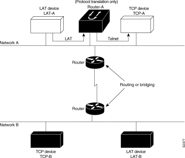
! Translation Configuration for Router-A only
!
interface ethernet 0
ip address 1.0.0.2 255.255.0.0
!
! enable LAT on this interface
lat enabled
!
interface serial 0
shutdown
no ip routing
default-gateway 1.0.0.100
!
translate lat TCP-A tcp TCP-A
translate lat TCP-B tcp TCP-B
translate tcp LAT-A lat lat-z
! etc...translate commands as required
The following example illustrates an X.29 access list. Incoming permit conditions are set for all IP hosts and LAT nodes that have specific characters in their names. All X.25 connections to a printer are denied. Outgoing connections are restricted.
!Permit all IP hosts and LAT nodes beginning with "VMS".
!Deny X.25 connections to the printer on line 5.
!
access-list 1 permit 0.0.0.0 255.255.255.255
lat access-list 1 permit ^VMS.*
x29 access-list 1 deny .*
!
line vty 5
access-class 1 in
!
!Permit outgoing connections for other lines.
!
!Permit IP access with the network 131.108
access-list 2 permit 131.108.0.0 0.0.255.255
!
!Permit LAT access to the prasad/gopala complexes.
lat access-list 2 permit ^prasad$
lat access-list 2 permit ^gopala$
!
!Permit X.25 connections to Infonet hosts only.
x29 access-list 2 permit ^31370
!
line vty 0 16
access-class 2 out
!
translate tcp 131.108.1.26 x25 5551234 access-class 2
The following profile script turns local edit mode on when the connection is made and establishes local echo and line termination upon receipt of a Return. The name linemode is used with the translate command to effect use of this script.
x29 profile linemode 2:1 3:2 15:1
translate tcp 131.108.1.26 x25 55551234 profile linemode
The X.3 PAD parameters are described in the appendix "X.3 PAD Parameters" later in this publication, and in the Cisco Access Connection Guide.
![]()
![]()
![]()
![]()
![]()
![]()
![]()
![]()
Posted: Mon Oct 21 12:35:27 PDT 2002
All contents are Copyright © 1992--2002 Cisco Systems, Inc. All rights reserved.
Important Notices and Privacy Statement.