|
|

Novell Internet Packet Exchange (IPX) is derived from the Xerox Network Systems (XNS) Internet Datagram Protocol (IDP). IPX and XNS have the following differences:
This chapter describes how to configure Novell IPX and provides configuration examples. For a complete description of the commands mentioned in this chapter, refer to the "Novell IPX Commands" chapter in the Router Products Command Reference publication. For historical background and a technical overview of Novell IPX, see the Internetworking Technology Overview publication.
Cisco's implementation of Novell's IPX protocol has been certified as providing full IPX router functionality. A Cisco router connects Ethernet, Token Ring, and FDDI networks, either directly or through high-speed serial lines (56 kbps to T1 speeds), X.25, or Frame Relay. At this time, the Cisco X.25 and T1 support is not compatible with Novell. This means that our routers must be used on both ends of T1 and X.25 circuits.
An IPX network address consists of a network number and a node number expressed in the format network.node.
The network number identifies a physical network. It is a four-byte (32-bit) quantity that must be unique throughout the entire IPX internetwork. The network number is expressed as eight hexadecimal digits. Our router software does not require that you enter all eight digits: you can omit leading zeros.
The node number identifies a node on the network. It is a 48-bit quantity, represented by dotted triplets of four-digit hexadecimal numbers.
The following is an example of an IPX network address:
4a.0000.0c00.23fe
In this example, the network number is 4a (more specifically, it is 0000004a), and the node number is 0000.0c00.23fe. All digits in the address are hexadecimal.
To configure IPX routing, complete the tasks in the following sections. At a minimum, you must enable IPX routing. The remaining tasks are optional.
See the end of this chapter for configuration examples.
To enable IPX routing, you must perform the tasks described in the following sections:
The first step in enabling IPX routing is to enable it on the router. To do so, perform the following global configuration task:
| Task | Command |
|---|---|
| Enable IPX routing on the router. | ipx routing [node] |
For an example of how to enable IPX routing, see the section "Enabling IPX Routing Example" later in this chapter.
 | Caution If you plan to use DECnet and IPX routing concurrently on the same interface, you should enable DECnet routing first, then enable IPX routing without specifying the optional Media Access Control (MAC) node number. If you enable IPX before enabling DECnet routing, routing for IPX will be disrupted because DECnet forces a change in the MAC-level node number. |
After you have enabled IPX routing on the router, you assign network numbers to individual interfaces. This has the effect of enabling IPX routing on those interfaces. When you enable IPX routing on an interface, you also can specify an encapsulation (frame type) to use for packets being transmitted on that network.
A single interface can support a single network or multiple logical networks. For a single network, you can configure any encapsulation type. Of course, it should match the encapsulation type of the servers and clients using that network number.
When assigning network numbers to an interface that supports multiple networks, you must specify a different encapsulation type for each network. Because multiple networks share the physical medium, this allows the router to determine which packets belong to which network. For example, you can configure up to four IPX networks on a single Ethernet cable, because four encapsulation types are supported for Ethernet. Again, the encapsulation type should match the servers and clients using the same network number.
The following sections describe how to enable IPX routing on interfaces that support a single network and those that support multiple networks.
To assign a network number to an interface that supports a single network, perform the following interface configuration task:
| Task | Command |
|---|---|
| Enable IPX routing on an interface. | ipx network number [encapsulation encapsulation-type] |
If you specify an encapsulation type, make sure you choose the one that matches that used by the servers and clients on that network.
For an example of how to enable IPX routing, see the section "Enabling IPX Routing Example" later in this chapter.
The first logical network you configure on an interface is considered the primary network. Any additional networks are considered secondary networks. Remember that each network on an interface must use a distinct encapsulation and that it should match the clients and servers using the same network number.
To configure multiple IPX networks on an interface, perform the following tasks in interface configuration mode:
To configure more than one secondary network, repeat step 2 as appropriate.
For an example of configuring multiple IPX networks on an interface, see the section "Enabling IPX Routing on Multiple Networks Example" later in this chapter.
Table 19-1 lists the encapsulation types you can use on IEEE interfaces and shows the correspondence between the encapsulation type and the IPX frame type.
| Interface Type | Encapsulation Type | IPX Frame Type |
|---|---|---|
| Ethernet | novell-ether (default) arpa sap snap | Ethernet_802.3 Ethernet_II Ethernet_802.2 Ethernet_Snap |
| Token Ring | sap (default) snap | Token-Ring Token-Ring_Snap |
| FDDI | snap (default) sap | Fddi_Snap Fddi_802.2 |
To control access to IPX networks, you create access lists and then apply them with filters to individual interfaces.
There are four types of IPX access lists that you can use to filter various kinds of traffic:
There are 13 different IPX filters that you can define for IPX interfaces. They fall into five groups:
Table 19-2 summarizes the types of filters and the commands you use to define them. Use the show ipx interfaces command to display the filters defined on an interface.
| Filter Type | Command Used to Define Filter |
|---|---|
| Generic filters | |
| Filter outbound packets based on protocol, address and address mask, and socket. | ipx access-group access-list-number |
| Routing table filters | |
| Control which networks are added to the routing table. | ipx input-network-filter access-list-number |
| Control which networks are advertised in routing updates. | ipx output-network-filter access-list-number |
| Control the routers from which updates are accepted. | ipx router-filter access-list-number |
| SAP filters | |
| Filter incoming service advertisements. | ipx input-sap-filter access-list-number |
| Filter outgoing service advertisements. | ipx output-sap-filter access-list-number |
| Control the routers from which SAP updates are accepted. | ipx router-sap-filter access-list-number |
| Filter list of servers in GNS response messages. | ipx output-gns-filter access-list-number |
| IPX NetBIOS filters | |
| Filter incoming packets by node name. | ipx netbios input-access-filter host name |
| Filter incoming packets by byte pattern. | ipx netbios input-access-filter bytes name |
| Filter outgoing packets by node name. | ipx netbios output-access-filter host name |
| Filter outgoing packets by byte pattern. | ipx netbios output-access-filter bytes name |
| Broadcast filters | |
| Control which broadcast packets are forwarded. | ipx helper-list access-list-number |
You perform the tasks in one or more of the following sections to control access to IPX networks:
Keep the following in mind when configuring IPX network access control:
To create access lists, you can perform one or more of the following tasks in global configuration mode:
Once you have created an access list, apply it to a filter on the appropriate interfaces as described in the sections that follow. This activates the access list.
Generic filters determine which packets to send out an interface based on the packet's source and destination addresses, IPX protocol type, and source and destination socket numbers.
To create generic filters, perform the following tasks:
Step 1 Create a standard or an extended access list.
Step 2 Apply a filter to an interface.
To create an access list, perform one of the following tasks in global configuration mode:
To apply a generic filter to an interface, perform the following task in interface configuration mode:
| Task | Command |
|---|---|
| Apply a generic filter to an interface. | ipx access-group access-list-number |
For an example of creating a generic filter, see the section "IPX Network Access Example" later in this chapter.
Routing table update filters control the entries that the router accepts for its routing table and the networks that it advertises in its routing updates.
To create filters to control updating of the routing table, perform the following tasks:
Step 1 Create a standard or an extended access list.
Step 2 Apply one or more routing filters to an interface.
To create an access list, perform one of the following tasks in global configuration mode:
To apply routing table update filters to an interface, perform one or more of the following tasks in interface configuration mode:
You can apply one of each of these filters to each interface.
A common source of traffic on Novell networks is Service Advertisement Protocol (SAP) messages, which are generated by NetWare servers and our routers when they broadcast their available services. To control how SAP messages from network segments or specific servers are routed among IPX networks, perform the following steps:
Step 1 Create a SAP access list.
Step 2 Apply one or more filters to an interface.
To create a SAP access list, perform the following task in global configuration mode:
| Task | Command |
|---|---|
| Create a SAP access list. | access-list access-list-number {deny | permit} network[.node] [network.node-mask] [service-type [server-name]] |
To apply SAP filters to an interface, perform one or more of the following tasks in interface configuration mode:
You can apply one of each of these filters to each interface.
For examples of creating and applying SAP filters, see the sections "SAP Input Filter Example" and "SAP Output Filter Example" later in this chapter.
To create filters for controlling which servers are included in the GNS responses sent by the router, perform the following tasks:
Step 1 Create a SAP access list.
Step 2 Apply a GNS filter to an interface.
To create a SAP access list, perform the following task in global configuration mode:
| Task | Command |
|---|---|
| Create a SAP access list. | access-list access-list-number {deny | permit} network[.node] [network.node-mask] [service-type [server-name]] |
To apply a GNS filter to an interface, perform the following task in interface configuration mode:
| Task | Command |
|---|---|
| Filter the list of servers in GNS response messages. | ipx output-gns-filter access-list-number |
Novell's IPX NetBIOS allows messages to be exchanged between nodes using alphanumeric names as well as node addresses. Therefore, the router lets you filter incoming and outgoing NetBIOS packets by the node name or by an arbitrary byte pattern (such as the node address) in the packet.
Keep the following in mind when configuring IPX NetBIOS access control:
To create filters for controlling IPX NetBIOS access, perform the following tasks:
Step 1 Create a NetBIOS access list.
Step 2 Apply the access list to an interface.
To create one or more NetBIOS access lists, perform one or both of the following tasks in global configuration mode:
To apply a NetBIOS access list to an interface, perform one or more of the following tasks in interface configuration mode:
You can apply one of each of these four filters to each interface.
Routers normally block all broadcast requests and do not forward them to other network segments. This is done to prevent the degradation of performance inherent in broadcast traffic over the entire network. You can define which broadcast messages get forwarded to other networks by applying a broadcast message filter to an interface.
To create filters for controlling broadcast messages, perform the following tasks:
Step 1 Create an access list.
Step 2 Apply a broadcast message filter to an interface.
To create an access list, perform one of the following tasks in global configuration mode:
To apply a broadcast message filter to an interface, perform the following tasks in interface configuration mode:
For examples of creating and applying broadcast message filters, see the section "Helper Facilities to Control Broadcasts Examples" later in this chapter.
To tune IPX network performance, perform the tasks in one of more of the following sections:
Cisco's implementation of Novell's IPX protocol has been certified as providing full IPX router functionality, as defined by Novell's IPX Router Specification, Version 1.10, published November 17, 1992.
To control specific aspects of IPX compliance, you can use a combination of global configuration and interface configuration commands. You can perform one or more of the following tasks in global configuration mode:
You can perform one or more of the following tasks in interface configuration mode:
To achieve full compliance, issue the following interface configuration commands on each interface configured for IPX:
You can also globally set interpacket delays for multiple-packet RIP and SAP updates to achieve full compliance, eliminating the need to set delays on each interface. To do so, issue the following commands from global configuration mode:
IPX uses the Routing Information Protocol (RIP) to determine the best path when several paths to a destination exist. RIP then dynamically updates the routing table. However, you might want to add static routes to the routing table to explicitly specify paths to certain destinations. Static routes always override any dynamically learned paths.
Be careful when assigning static routes. When links associated with static routes are lost, traffic may stop being forwarded or traffic may be forwarded to a nonexistent destination, even though an alternative path might be available.
To add a static route to the router's routing table, perform the following task in global configuration mode:
| Task | Command |
|---|---|
| Add a static route to the routing table. | ipx route network network.node |
You can set the interval between IPX RIP updates on a per-interface basis. You can also specify the delay between the packets of a multiple-packet RIP update on a per-interface or global basis. Additionally, you can specify the delay between packets of a multiple-packet triggered RIP update on a per-interface or global basis.
You can set RIP update times only in a configuration in which all routers are our routers or in which the IPX routers allow configurable timers. The timers for all routers connected to the same network segment should be the same. The RIP update value you choose affects internal IPX timers as follows:
You might want to set a delay between the packets in a multiple-packet update if there are some slower PCs on the network or on slower speed interfaces.
To adjust RIP update times on a per-interface basis, perform any or all of the following tasks in interface configuration mode:
To adjust RIP update times on a global basis, perform any or all of the following tasks in global configuration mode:
| Task | Command |
|---|---|
| Adjust the delay between multiple-packet routing updates sent on all interfaces. | ipx default-output-rip-delay delay |
| Adjust the delay between multiple-packet triggered routing updates sent on all interfaces. | ipx default-triggered-rip-delay delay |
Servers use SAP to advertise their services via broadcast packets. Routers store this information in the SAP table, also known as the Server Information Table (SIT). This table is updated dynamically. You might want to explicitly add an entry to the SIT so that clients always use the services of a particular server. Static SAP assignments always override any identical entries in the SAP table that are learned dynamically, regardless of hop count. If a dynamic route that is associated with a static SAP entry is lost or deleted, the router will not announce the static SAP entry until it relearns the route.
To add a static entry to the router's SAP table, perform the following task in global configuration mode:
| Task | Command |
|---|---|
| Specify a static SAP table entry. | ipx sap service-type name network.node socket hop-count |
The router maintains a list of SAP requests to process, including all pending Get Nearest Server (GNS) queries from clients attempting to reach servers. When the network is restarted, the router can be inundated with hundreds of requests for servers. Typically, many of these are repeated requests from the same clients. You can configure the maximum length allowed for the pending SAP requests queue. SAP requests received when the queue is full are dropped, and the client must resend them.
To set the queue length for SAP requests, perform the following task in global configuration mode:
| Task | Command |
|---|---|
| Configure the maximum SAP queue length. | ipx sap-queue-maximum number |
You can adjust the interval at which SAP updates are sent. You can also set the delay between packets of a multiple-packet SAP update on a per-interface or global basis. Additionally, you can specify the delay between packets of a multiple-packet triggered SAP update on a per-interface or global basis.
Changing the interval at which SAP updates are sent is most useful on limited-bandwidth, point-to-point links or on X.25 and Frame Relay multipoint interfaces. You should ensure that all Novell servers and routers on a given network have the same SAP interval. Otherwise, they might decide that a server is down when it is really up.
Adjusting the delay between packets sent in a multiple-packet SAP update is useful when the IPX network has slow IPX servers and/or routers. Setting a delay between packets in a multiple-packet SAP update forces our router to slow its output of SAP packets.
To modify the SAP timers on a per-interface basis, perform any or all of the following tasks in interface configuration mode:
To adjust SAP update times on a global basis (eliminating the need to configure delays on a per interface basis), perform any or all of the following tasks in global configuration mode:
| Task | Command |
|---|---|
| Adjust the interpacket delay of multiple-packet SAP updates sent on all interfaces. | ipx default-output-sap-delay delay |
| Adjust the interpacket delay of multiple-packet triggered SAP updates sent on all interfaces. | ipx default-triggered-sap-delay delay |
You can set the maximum number of equal-cost, parallel paths to a destination. (Note that when paths have differing costs, the router chooses lower-cost routes in preference to higher-cost routes.) The router then distributes output on a packet-by-packet basis in round-robin fashion. That is, the first packet is sent along the first path, the second packet along the second path, and so on. When the final path is reached, the next packet is sent to the first path, the next to the second path, and so on. This round-robin scheme is used whether or not fast switching is enabled.
The cost of a path is determined by ticks, with hop count used as a tie breaker.
Limiting the number of equal-cost paths can save memory on routers with limited memory or very large configurations. Additionally, in networks with a large number of multiple paths and systems with limited ability to cache out-of-sequence packets, performance might suffer when traffic is split between many paths.
To set the maximum number of paths on the router, perform the following task in global configuration mode:
| Task | Command |
|---|---|
| Set the maximum number of equal-cost paths to a destination. | ipx maximum-paths paths |
You can set the method in which the router responds to SAP (GNS) requests, and you can set the delay time in responding to these requests.
The default method of responding to GNS requests is to respond with the server whose availability was learned most recently.
To control responses to GNS requests, perform one or both of the following tasks in global configuration mode:
| Task | Command |
|---|---|
| Respond to GNS requests using a round-robin selection method. | ipx gns-round-robin |
| Set the delay when responding to GNS requests. | ipx gns-response-delay [milliseconds] |
Routers normally block all broadcast requests and do not forward them to other network segments. This is done to prevent the degradation of performance over the entire network. You can enable the forwarding of broadcast messages (except type 20 broadcasts) to other networks and forward all other unrecognized broadcast messages. These are non-RIP and non-SAP packets that are not addressed to the local network. Forwarding broadcast messages is sometimes useful when a network segment does not have an end-host capable of servicing a particular type of broadcast request. You can specify the address of a server, network, or networks that can process the broadcast messages.
Our routers support all-networks flooded broadcasts (sometimes referred to as all-nets flooding). These are broadcast messages that are forwarded to all networks. Use all-nets flooding carefully and only when necessary, because the receiving networks may be overwhelmed to the point that no other traffic can traverse them.
Use the ipx helper-list command, described earlier in this chapter, to define access lists that control which broadcast packets get forwarded.
To specify a helper address for forwarding broadcast messages, perform the following task in interface configuration mode:
| Task | Command |
|---|---|
| Specify a helper address for forwarding broadcast messages. | ipx helper-address network.node |
You can specify multiple helper addresses on a given interface.
For an example of using helper addresses to forward broadcast messages, see the section "Helper Facilities to Control Broadcasts Examples" later in this chapter.
NetBIOS over IPX uses type 20 propagation broadcast packets flooded to all networks to get information about the named nodes on the network. NetBIOS uses a broadcast mechanism to get this information, because it does not implement a network layer.
Routers normally block all broadcast requests. By enabling type 20 packet propagation, IPX interfaces on the router may accept and forward type 20 propagation packets. Before forwarding (flooding) the packets, the router performs loop detection as described by the IPX router specification.
You can configure the router to apply extra checks to type 20 propagation packets above and beyond the loop detection described in the IPX specification. These checks are the same ones that are applied to helpered all-nets broadcast packets. They can limit unnecessary duplication of type 20 broadcast packets. The extra helper checks are as follows:
While this extra checking increases the robustness of type 20 propagation packet handling by decreasing the amount of unnecessary packet replication, it has two side effects:
You can enable the forwarding of type 20 packets on individual interfaces, and you can restrict the acceptance and forwarding of type 20 packets. The tasks to do this are described in the following sections.
By default, type 20 propagation packets are dropped by the router. You can configure the router to receive type 20 propagation broadcast packets and forward (flood) them to other network segments, subject to loop detection.
To enable the receipt and forwarding of type 20 packets, perform the following task in interface configuration mode:
| Task | Command |
|---|---|
| Optionally enable type 20 packet propagation if you want to forward type 20 broadcast traffic across the router. | ipx type-20-propagation |
For incoming type 20 propagation packets, the router is configured by default to accept packets on all interfaces enabled to receive type 20 propagation packets. You can configure the router to accept packets only from the single network that is the primary route back to the source network. This means that similar packets from the same source that are received via other networks will be dropped.
Checking of incoming type 20 propagation broadcast packets is done only if the interface is configured to receive and forward type 20 packets.
To impose restrictions on the receipt of incoming type 20 propagation packets in addition to the checks defined in the IPX specification, perform the following global configuration task:
| Task | Command |
|---|---|
| Restrict the acceptance of IPX type 20 propagation packets. | ipx type-20-input-checks |
For outgoing type 20 propagation packets, the router is configured by default to send packets on all interfaces enabled to send type 20 propagation packets, subject to loop detection. You can configure the router to send these packets only to networks that are not routes back to the source network. (The router uses the current routing table to determine routes.)
Checking of outgoing type 20 propagation broadcast packets is done only if the interface is configured to receive and forward type 20 packets.
To impose restrictions on the transmission of type 20 propagation packets and to forward these packets to all networks using only the checks defined in the IPX specification, perform the following global configuration task:
| Task | Command |
|---|---|
| Restrict the forwarding of IPX type 20 propagation packets. | ipx type-20-output-checks |
Fast switching allows higher throughput by switching a packet using a cache created by previous packets. Fast switching is enabled by default on all interfaces.
Packet transfer performance is generally better when fast switching is enabled. However, you might want to disable fast switching in order to save memory space on interface cards and to help avoid congestion when high-bandwidth interfaces are writing large amounts of information to low-bandwidth interfaces.
To disable IPX fast switching, perform the following task in interface configuration mode:
| Task | Command |
|---|---|
| Disable IPX fast switching. | no ipx route-cache sse |
The silicon switching engine (SSE) is on the Silicon Switch Processor (SSP) board in the Cisco 7000 series. SSE switching contributes to very fast packet processing by allowing the SSE to perform switching independently of the system processor.
To enable SSE switching, perform the following task in interface configuration mode:
| Task | Command |
|---|---|
| Enable the SSE switching cache. | ipx route-cache sse |
Autonomous switching provides faster packet switching by allowing the ciscoBus controller to switch packets independently without having to interrupt the system processor. It is available only in Cisco 7000 systems and in AGS+ systems with high-speed network controller cards, such as the CSC-HSCI, CSC-MEC, CSC-FCI, CSC-C2FCIT, and CSC-C2CTR, and with a CSC-CCTL2 ciscoBus controller running Microcode Version 11.0 or later. Autonomous switching is disabled by default on all interfaces.
To enable autonomous switching, perform the following task in interface configuration mode:
| Task | Command |
|---|---|
| Enable autonomous switching. | ipx route-cache cbus |
Some IPX end hosts reject Ethernet packets that are not padded. Certain topologies can result in such packets being forwarded onto a remote Ethernet network. Under specific conditions, you can use padding on intermediate media as a temporary workaround for this problem.
To enable the padding of odd-length packets, perform the following tasks in interface configuration mode:
| Task | Command |
|---|---|
| Step 1 Disable fast switching. | no ipx route-cache |
| Step 2 Enable the padding of odd-length packets. | ipx pad-process-switched-packets |
To repair corrupted network numbers on an interface, perform the following tasks in interface configuration mode:
| Task | Command |
|---|---|
| Step 1 Disable fast switching. | no ipx route-cache |
| Step 2 Repair corrupted network numbers. | ipx source-network-update |
| Caution The ipx source-network-update interface configuration command interferes with the proper working of OS/2 Requestors. Do not use this command in a network that has OS/2 Requestors. |
| Caution Do not use the ipx source-network-update interface configuration command on interfaces on which NetWare servers are using internal network numbers (that is, all 3.1x and 4.0 servers). |
IPX accounting allows you to collect information about IPX packets and the number of bytes that are switched through the router. You collect information based on the source and destination IPX address. Accounting tracks only IPX traffic that is routed through the router; it does not track traffic generated by or terminating at the router.
IPX accounting statistics are accurate even if IPX fast switching is enabled or if IPX access lists are being used. However, IPX accounting does not keep statistics if autonomous switching is enabled.
The router software maintains two accounting databases: an active database and a checkpointed database.
To enable IPX accounting, perform the following task in interface configuration mode:
| Task | Command |
|---|---|
| Enable IPX accounting. | ipx accounting |
To control IPX accounting on the router, perform one or more of the following tasks in global configuration mode:
You can configure IPX over dial-on-demand routing (DDR), Frame Relay, Point-to-Point Protocol (PPP), Switched Multimegabit Data Service (SMDS), and X.25 networks. To do this, you configure the appropriate address mappings as described in the appropriate chapter. You can also route IPX packets over serial interfaces configured for DDR, and you can configure the IPXWAN protocol.
IPX sends periodic watchdog (keepalive) packets. Therefore, when configuring IPX over DDR, you might want to disable the generation of these packets. This is not an issue for the other WAN protocols, because they establish dedicated connections rather than establishing connections only as needed.
Novell IPX watchdog packets are keepalive packets that are sent from servers to clients after a client session has been idle for approximately 5 minutes. On a DDR link, this means that a call would be made every 5 minutes, regardless of whether there were data packets to send. You can prevent these calls from being made by configuring the router to respond to the server's watchdog packets on a remote client's behalf. This is sometimes referred to as "spoofing the server." To keep the serial interface idle when only watchdog packets are being sent, refer to the tasks described in the "Configuring DDR" chapter. For an example of configuring IPX over DDR, see the section "IPX over DDR Example" later in this chapter.
Our routers support the IPXWAN protocol, as defined in RFC 1362. IPXWAN allows two routers that are running IPX routing to connect via a serial link to another router, possibly from another manufacturer, that is also running IPX routing and using IPXWAN.
You can use the IPXWAN protocol over PPP. You can also use it over HDLC; however, the routers at both ends of the serial link must be our routers.
To configure IPXWAN, perform the following tasks in interface configuration mode on a serial interface:
| Task | Command |
|---|---|
| Step 1 Ensure that you have not configured an IPX network number on the interface. | no ipx network number |
| Step 2 Enable PPP. | encapsulation ppp1 |
| Step 3 Enable IPXWAN. | ipx ipxwan local-node number local-server [retry-interval] [retry-attempts] |
To monitor a Novell IPX network, perform one or more of the following tasks at the EXEC prompt:
This section provides configuration examples for the following IPX configuration situations:
The following configuration commands enable IPX routing, defaulting the IPX host address to that of the first IEEE-conformance interface (in this example, Ethernet 0). Routing is then enabled on Ethernet 0 and Ethernet 1 for IPX networks 2abc and 1def, respectively.
ipx routing
interface ethernet 0
ipx network 2abc
interface ethernet 1
ipx network 1def
The following example creates four networks on Ethernet interface 0:
interface ethernet 0
ipx network 1
ipx encapsulation novell-ether
ipx network 2 encapsulation snap secondary
ipx network 3 encapsulation arpa secondary
ipx network 4 encapsulation iso1 secondary
Any configuration parameters that you specify on this interface are applied to all the logical networks. For example, if you set the routing update timer to 120 seconds, this value is used on all four networks.
If you administratively bring down Ethernet interface 0 using the shut interface configuration command, all four networks are shut down. You cannot bring down each network independently using the shut command; however, you can do this using the ipx down command.
To bring down network 1, use the following command:
ipx down 1
To shut down all four networks on the interface and remove all the networks on the interface, use one of the following commands:
no ipx network
no ipx network 1
To remove one of the secondary networks on the interface (in this case, network 2), use this command:
no ipx network 2
When you configure the router to transport IPX packets over a serial interface that is running a WAN protocol such as X.25 or PPP, you specify how the packet will be encapsulated for transport. This encapsulation is not the same as the encapsulation used on an IPX LAN interface. Figure 19-1 illustrates IPX over a WAN interface.
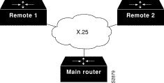
The following examples configure a serial interface for X.25 encapsulation and for several IPX subinterfaces used in a nonmeshed topology.
hostname Main
!
no ip routing
novell routing 0000.0c17.d726
!
interface Ethernet0
no ip address
Novell network 100
media-type 10BaseT
!
interface Serial0
no ip address
shutdown
!
interface Serial1
no ip address
encapsulation x25
x25 address 33333
x25 htc 28
!
interface Serial1.1 point-to-point
no ip address
novell network 2
x25 map novell 2.0000.0c03.a4ad 11111 BROADCAST
!
interface Serial1.2 point-to-point
no ip address
novell network 3
x25 map novell 3.0000.0c07.5e26 55555 BROADCAST
hostname Remote1
!
no ip routing
novell routing 0000.0c03.a4ad
!
interface Ethernet0
no ip address
novell network 1
!
interface Serial0
no ip address
encapsulation x25
novell network 2
x25 address 11111
x25 htc 28
x25 map novell 2.0000.0c17.d726 33333 BROADCAST
hostname Remote2
!
no ip routing
novell routing 0000.0c07.5e26
!
interface Ethernet0
no ip address
novell network 4
media-type 10BaseT
!
interface Serial0
no ip address
shutdown
!
interface Serial1
no ip address
encapsulation x25
novell network 3
x25 address 55555
x25 htc 28
x25 map novell 3.0000.0c17.d726 33333 BROADCAST
The following example configures IPX to run over the configuration illustrated in Figure 1-2. In this configuration, an IPX client is separated from its server by a DDR telephone line. Once the server and client have established contact, the server will send keepalive packets regularly. The purpose of these packets is to ensure that the connection between the server and the client is still functional; these packets contain no other information. Servers send keepalive packets approximately every 5 minutes. If you were to allow Router B to forward the server's watchdog packets to Router A and the client, Router B would have to telephone Router A every 5 minutes just to send the watchdog packets.
Instead of having Router B telephone Router A only to send keepalive packets, you can enable watchdog spoofing on Router B. This way, when the server connected to this router sends keepalive (watchdog) packets, Router B will respond on behalf of the remote client (the client connected to Router A).
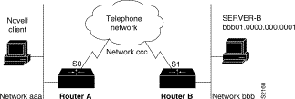
!configure the router to which the client is connected
ipx routing 0000.0c00.59e8
interface serial 0
no keepalive
dialer in-band
dialer string 8986
ipx network aaa
pulse-time 1
dialer-group 1
!
ipx route 42 aaa.0000.0x01.d877
!
access-list 800 permit ffffffff 42.0000.0000.0001
dialer-list 1 list 800
!configure the router to which the server is attached
ipx routing 0000.0x01.d877
interface serial 1
no ip address
bandwidth 56
no keepalive
dialer in-band
ipx network bbb
pulse-time 1
no ipx route-cache
no ipx-route-cache cbus
!enable watchdog spoofing on the server's router
ipx watchdog-spoof
Using access lists to manage traffic routing can be a powerful tool in overall network control. However, it requires a certain amount of planning and the appropriate application of several related commands. Figure 1-3 illustrates a network featuring two routers on two network segments.
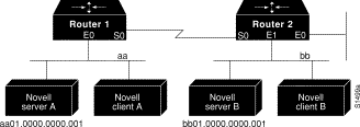
Suppose you want to prevent clients and servers on Network aa from using the services on Network bb, but you want to allow the clients and servers on Network bb to use the services on Network aa. To do this, you would need an access list on the E1 interface on Router 2 that blocks all packets coming from Network aa and destined for Network bb. You would not need any access list on the E0 interface on Router 1.
You would configure the S0 interface on Router 2 with the following commands:
ipx routing
access-list 800 deny aa bb01
access-list 800 permit -1 -1
interface serial 0
ipx network bb
ipx access-group 800
SAP input filters allow a router to determine whether or not to accept information about a service. Router C1, illustrated in Figure 1-4, will not accept and, consequently not advertise, any information about Novell server F. However, Router C1 will accept information about all other servers on the network 3c. Router C2 receives information about servers D and B.
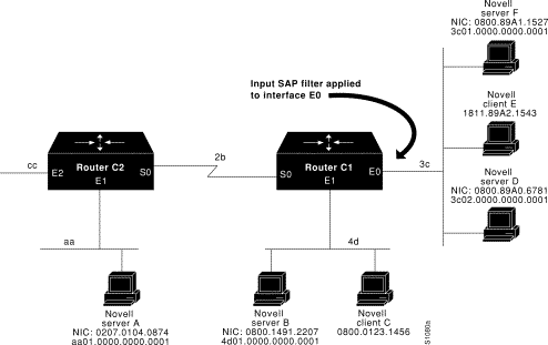
The following example configures Router C1. The first line denies server F. It accepts all other servers.
access-list 1000 deny 3c01.0000.0000.0001
access-list 1000 permit -1
interface ethernet 0
ipx network 3c
ipx input-sap-filter 1000
interface ethernet 1
ipx network 4d
interface serial 0
ipx network 2b
SAP output filters are applied prior to the router sending information out a specific interface. In the example that follows, Router C1 (illustrated in Figure 1-5) is prevented from advertising information about Novell server A out interface Ethernet 1, but can advertise server A on network 3c.
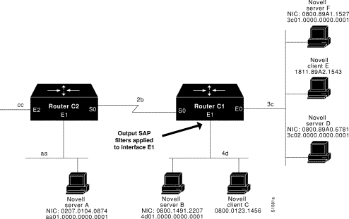
The following example refers to Router C1. The first line denies server A. All other servers are permitted.
access-list 1000 deny aa01.0000.0000.0001
access-list 1000 permit -1
interface ethernet 0
novell net 3c
interface ethernet 1
ipx network 4d
ipx output-sap-filter 1000
interface serial 0
ipx network 2b
The following is an example of using a NetBIOS host name to filter IPX NetBIOS frames. The example denies all outgoing IPX NetBIOS frames with a NetBIOS host name of Boojum on Ethernet interface 0:
netbios access-list host token deny Boojum
netbios access-list host token permit *
!
ipx routing 0000.0c17.d45d
!
interface ethernet 0
 ipx network 155 encapsulation ARPA
 ipx output-rip-delay 60
 ipx triggered-rip-delay 30
 ipx output-sap-delay 60
 ipx triggered-sap-delay 30
 ipx type-20-propagation
 ipx netbios output-access-filter host token
 no mop enabled
!
interface ethernet 1
 no ip address
 ipx network 105
!
interface fddi 0
 no ip address
 no keepalive
ipx network 305 encapsulation SAP
!
interface serial 0
 no ip address
 shutdown
!
interface serial 1
 no ip address
 no keepalive
 ipx network 600
 ipx output-rip-delay 100
 ipx triggered-rip-delay 60
 ipx output-sap-delay 100
 ipx triggered-sap-delay 60
 ipx type-20-propagation
The following is an example of using a byte pattern to filter IPX NetBIOS frames. This example permits IPX NetBIOS frames from IPX network numbers that end in 05. This means that all IPX NetBIOS frames from Ethernet interface 1 (network 105) and FDDI interface 0 (network 305) will be forwarded by serial interface 0, but this interface will filter out and not forward all frames from Ethernet interface 0 (network 155).
netbios access-list bytes finigan permit 2 **05
!
ipx routing 0000.0c17.d45d
!
ipx default-output-rip-delay 1000
ipx default-triggered-rip-delay 100
ipx default-output-sap-delay 1000
ipx default-triggered-sap-delay 100
!
interface ethernet 0
 ipx network 155 encapsulation ARPA
 ipx output-rip-delay 55
 ipx triggered-rip-delay 55
 ipx output-sap-delay 55
 ipx triggered-sap-delay 55
 ipx type-20-propagation
 media-type 10BaseT
!
interface ethernet 1
 no ip address
 ipx network 105
 ipx output-rip-delay 55
 ipx triggered-rip-delay 55
 ipx output-sap-delay 55
 ipx triggered-sap-delay 55
 media-type 10BaseT
!
interface fddi 0
 no ip address
 no keepalive
 ipx network 305 encapsulation SAP
 ipx output-sap-delay 55
 ipx triggered-sap-delay 55
!
interface serial 0
 no ip address
 shutdown
!
interface serial 1
 no ip address
 no keepalive
 ipx network 600
 ipx type-20-propagation
 ipx netbios input-access-filter bytes finigan
The following examples illustrate how to control broadcast messages on IPX networks. Note that in the following examples, packet type 2 is used. This type has been chosen arbitrarily; the actual type to use depends on the specific application.
All broadcast packets are normally blocked by the router. However, type 20 propagation packets may be forwarded, subject to certain loop-prevention checks. Other broadcasts may be directed to a set of networks or a specific host (node) on a segment. The following examples illustrate these options.
Figure 1-6 shows a router (C1) connected to several Ethernet interfaces. In this environment, all IPX clients are attached to segment aa, while all servers are attached to segments bb and dd. In controlling broadcasts, the following conditions are to be applied:
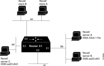
Note that network segment dd is connected to interface E3 (unlabeled in figure). Also note that Novell server A on network segment dd should be labeled Novell server C.
The following example configures the router shown in Figure 1-6. The first line permits broadcast traffic of type 2 from network aa. The interface and network commands configure each specific interface. The ipx helper-address commands permit broadcast forwarding from network aa to bb and from network aa to dd. The helper list allows type 2 broadcasts to be forwarded. A specific permission to allow type 20 broadcasts to be forwarded between networks aa and dd is also required.
access-list 900 permit 2 aa
interface ethernet 0
ipx network aa
ipx type-20-propagation
ipx helper-address bb.ffff.ffff.ffff
ipx helper-address dd.ffff.ffff.ffff
ipx helper-list 900
interface ethernet 1
ipx network bb
interface ethernet 3
ipx network dd
ipx type-20-propagation
This configuration means that any network that is downstream from network aa (for example, some arbitrary network aa1) will not be able to broadcast (type 2) to network bb through Router C1 unless the routers partitioning networks aa and aa1 are configured to forward these broadcasts with a series of configuration entries analogous to the example provided for Figure 1-5. These entries must be applied to the input interface and be set to forward broadcasts between directly connected networks. In this way, such traffic can be passed along in a directed manner from network to network. A similar situation exists for type 20 packets.
The following example rewrites the ipx helper-address interface configuration command line to direct broadcasts to server A:
ipx helper-address bb.00b4.23cd.110a
! Permits node-specific broadcast forwarding to
! Server A at address 00b4.23cd.110a on network bb
In some networks, it might be necessary to allow client nodes to broadcast to servers on multiple networks. If you configure your router to forward broadcasts to all attached networks, you are flooding the interfaces. In the environment illustrated in Figure 1-7, client nodes on network 2b1 must obtain services from IPX servers on networks 3c2, 4a1, and 5bb through Router C1. To support this requirement, use the flooding address (-1.ffff.ffff.ffff) in your ipx helper-address interface configuration command specifications.
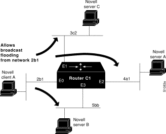
In the following example, the first line permits traffic of type 2 from network 2b1. Then the first interface is configured with a network number. The all-nets helper address is defined and the helper list limits forwarding to type 2 traffic.Type 2 broadcasts from network 2b1 are forwarded to all directly connected networks. All other broadcasts, including type 20, are blocked. To permit broadcasts, delete the ipx helper-list entry. To allow type 20 broadcast, enable the ipx type-20-propagation interface configuration command on all interfaces.
access-list 901 permit 2 2b1
interface ethernet 0
ipx network 2b1
ipx helper-address -1.ffff.ffff.ffff
ipx helper-list 901
interface ethernet 1
ipx network 3c2
interface ethernet 2
ipx network 4a1
interface ethernet 3
ipx network 5bb
The following example configures all-nets flooding on an interface.
interface ethernet 0
ipx network 23
ipx helper-address -1.FFFF.FFFF.FFFF
As a result of this configuration, Ethernet interface 0 will forward all broadcast messages (except type 20) to all the networks it knows how to reach. This flooding of broadcast messages might overwhelm these networks with so much broadcast traffic that no other traffic may be able to pass on them.
The following example configures two Ethernet network segments that are connected via a serial link. (See Figure 1-8.) On Router A, IPX accounting is enabled on both the input and output interfaces (that is, on Ethernet interface 0 and serial interface 0). This means that statistics are gathered for traffic traveling in both directions (that is, out to the Ethernet network and out the serial link). However, on Router B, IPX accounting is enabled only on the serial interface and not on the Ethernet interface. This means that statistics are gathered only for traffic that passes out the router on the serial link.
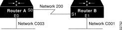
ipx routing
interface ethernet 0
no ip address
ipx network C003
ipx accounting
interface serial 0
no ip address
ipx network 200
ipx accounting
ipx routing
interface ethernet 1
no ip address
no keepalive
ipx network C001
no mop enabled
interface serial 1
no ip address
ipx network 200
ipx accounting
|
|