cc/td/doc/product/sn5000
hometocprevnextglossaryfeedbacksearchhelp
PDF

Table Of Contents

Cisco 10-Gigabit Fibre Channel X2 Transceiver Module Installation Note

Contents

Overview

Required Tools

Installing the 10-Gigabit Fibre Channel X2 Transceiver Module

Removing the 10-Gigabit Fibre Channel X2 Transceiver Module

Related Documentation

Release Notes

Compatibility Information

Regulatory Compliance and Safety Information

Hardware Installation

Cisco Fabric Manager

Command-Line Interface

Troubleshooting and Reference

Installation and Configuration Note

Obtaining Documentation, Obtaining Support, and Security Guidelines


Cisco 10-Gigabit Fibre Channel X2 Transceiver Module Installation Note


Release Date: April 30, 2007

Text Part Number: 78-17639-02

This document provides installation instructions for the 10-Gigabit Fibre Channel X2 transceiver modules listed in Table 1. The X2 transceiver is a hot-swappable input/output (I/O) device that plugs into a 10-Gigabit Fibre Channel port. The X2 transceiver links the switch to a fiber-optic or copper network.

Table 1 10-Gigabit Fibre Channel X2 Transceiver Modules

X2 Transceiver Module Product Number
Description

DS-X2-FC10G-SR

Cisco 10GFC-SR X2 transceiver module for SMF, dual SC connector

DS-X2-FC10G-LR

Cisco 10GFC-LR X2 transceiver module for SMF, dual SC connector

DS-X2-FC10G-ER

Cisco 10GFC-ER X2 transceiver module for SMF, dual SC connector


Note 
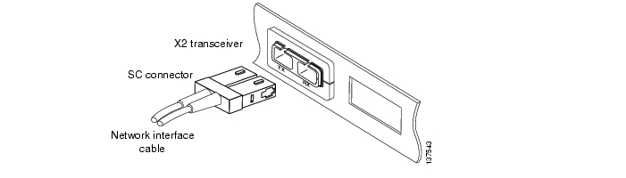
The dual SC connector on the X2 transceiver supports network interface cables with either Physical Contact (PC) or Ultra-Physical Contact (UPC) polished face types. The dual SC connector on the X2 transceiver does not support network interface cables with an Angle-Polished Connector (APC) face type.


Contents

This document contains these sections:

Overview

Required Tools

Installing the 10-Gigabit Fibre Channel X2 Transceiver Module

Removing the 10-Gigabit Fibre Channel X2 Transceiver Module

Related Documentation

Obtaining Documentation, Obtaining Support, and Security Guidelines

Overview

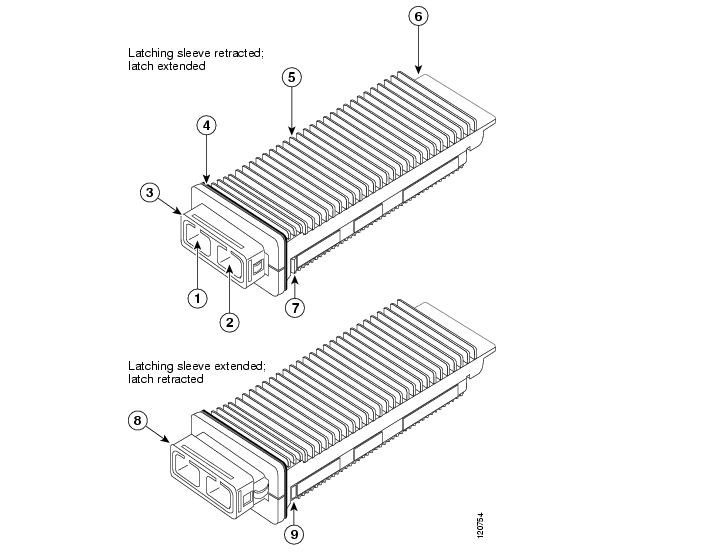
The 10-Gigabit Fibre Channel X2 transceiver module is a hot-swappable I/O device that plugs into a 10-Gigabit Fibre Channel port. (See Figure 1.) The X2 transceiver connects the electrical circuitry of the switch to an optical or copper network.

Figure 1 10-Gigabit Fibre Channel X2 Transceiver Module (Optical)

1

Transmit optical bore

6

Module connector

2

Receive optical bore

7

Latch (extended)

3

Latching sleeve (retracted)

8

Latching sleeve (extended)

4

EMI gasket

9

Latch (retracted)

5

Transceiver heat sink


Table 2 lists the port cabling specifications for the 10-Gigabit Fibre Channel X2 transceiver modules. Table 3 lists the X2 transceiver optical transmit and receive specifications.

Table 2 X2 Transceiver Port Cabling Specifications

X2 Product Number
Wavelength (nm)
Cable Type
Core Size (microns)
Modal Bandwidth (MHz/km)
Maximum Cabling Distance

DS-X2-FC10G-SR

850

SMF

62.5

62.5

50.0

50.0

50.0

160

200

400

500

2000

26 m (85.3 ft)

33 m (108.3 ft)

66 m (216.5 ft)

82 m (269 ft)

300 m (984.3 ft)

DS-X2-FC10G-LR

1310

SMF

G.652 fiber

10 km (6.21 miles)

DS-X2-FC10G-ER

1550

SMF

G.652 fiber

40 km (24.8 miles)


Table 3 X2 Transceiver Optical Transmit and Receive Specifications

X2 Product Number
Transceiver Type
Transmit Power (dBm)
Receive Power (dBm)
Transmit and Receive Wavelength (nm)

DS-X2-FC10G-SR

10GFC-SR, 850-nm SMF

— (Max)

-7.3 (Min)

-1.0 (Max)

-9.9 (Min)

840 to 860

DS-X2-FC10G-LR

10GFC-LR, 1310-nm SMF

0.5 (Max)

-8.2 (Min)

0.5 (Max)

-14.4 (Min)

1260 to 1355

DS-X2-FC10G-ER

10GFC-ER, 1550-nm SMF

4.0 (Max)

-4.7 (Min)

-1.0 (Max)

-15.8 (Min)

1550


Required Tools

You need the following tools to install the 10-Gigabit Fibre Channel X2 transceiver module:

Small flat-blade screwdriver for removing the X2 transceiver socket covers.

Wrist strap or other personal grounding device to prevent ESD occurrences.

Antistatic mat or antistatic foam to place the transceiver on.

Fiber-optic end-face cleaning tools and inspection equipment. For complete information on inspecting and cleaning fiber-optic connections, refer to the white paper at this URL: http://www.cisco.com/en/US/tech/tk482/tk876/technologies_white_paper09186a0080254eba.shtml

Installing the 10-Gigabit Fibre Channel X2 Transceiver Module

The 10-Gigabit Fibre Channel X2 transceiver module can have either a spring-loaded latch sleeve or a latch sleeve that is not spring loaded. Both transceiver types are functionally identical.


Note This installation procedure applies to both the spring loaded and non-spring loaded X2 transceivers.


Caution The X2 transceiver is a static-sensitive device. Always use an ESD wrist strap or similar individual grounding device when handling X2 transceivers or coming into contact with system modules.


Note Before you install the transceiver module, refer to the Regulatory Compliance and Safety Information for the Cisco 9000 Family for important safety information.


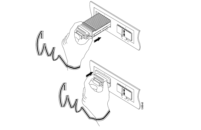
To install an X2 transceiver, follow these steps:


Step 1 Use a small flat-blade screwdriver, to carefully pry the X2 transceiver port cover off of the system module faceplate.

Use the two arrows on the port cover as guides for inserting the screwdriver blade. Save the port cover for future use.

Step 2 Remove the X2 transceiver from its protective packaging.


Note Do not remove the optical bore dust plugs until directed to do so later in the procedure.


Step 3 Check the label on the X2 transceiver body to verify that you have the correct model for your network.

Step 4 Follow these steps to install the X2 transceiver:

a. Insert the X2 transceiver into the transceiver socket on the system module front panel. (See Figure 2, top view.) Continue sliding the X2 transceiver into the socket until the X2 transceiver EMI gasket is flush against the system module faceplate. The X2 transceiver connector is now mated to the socket connector.

b. Verify that the X2 transceiver latches are fully engaged and secure by sliding the transceiver latching sleeve toward the system module faceplate. (See Figure 2, bottom view.)


Caution If the latches are not fully engaged, you may accidently disconnect the X2 transceiver.

Figure 2 Installing the 10-Gigabit Fibre Channel X2 Transceiver Module


Note 10-Gigabit Fibre Channel X2 transceivers are keyed to prevent incorrect insertion.


Step 5 Follow these steps to cable an optical X2 transceiver:


Note Before removing the dust plugs and making any optical connections, observe the following guidelines:

Always keep the protective dust plugs on the unplugged fiber-optic cable connectors and the transceiver optical bores until you are ready to make a connection.

Always inspect and clean the SC connector end-faces just before making any connections.

Always grasp the SC connector housing to plug or unplug a fiber-optic cable.


Tip For complete information on inspecting and cleaning fiber-optic connections, refer to the white paper at this URL:

http://www.cisco.com/en/US/tech/tk482/tk876/technologies_white_paper09186a0080254eba.shtml


a. Remove the dust plugs from the optical network interface cable SC connectors. Save the dust plugs for future use.

b. Inspect and clean the SC connector's fiber-optic end-faces.

c. Remove the dust plugs from the X2 transceiver module optical bores.

d. Immediately attach the network interface cable SC connectors to the X2 transceiver module. (See Figure 3.)

Figure 3 Cabling an Optical 10-Gigabit Fibre Channel X2 Transceiver Module

Removing the 10-Gigabit Fibre Channel X2 Transceiver Module


Note This removal procedure applies to both the spring loaded and non-spring loaded X2 transceivers.


Caution The X2 transceiver is a static-sensitive device. Always use an ESD wrist strap or similar individual grounding device when handling X2 transceivers or coming into contact with modules.

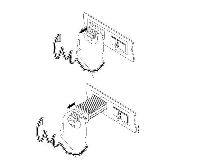
To remove an X2 transceiver, follow these steps:


Step 1 Disconnect the network interface cable from the X2 transceiver connectors. If this is an optical X2 transceiver, immediately reinstall the dust plugs in the X2 transceiver optical bores and the fiber-optic cable SC connectors.

Step 2 Grip the sides of the X2 transceiver latching sleeve with your thumb and forefinger, and pull the latching sleeve out to release the X2 transceiver from the socket connector. (See Figure 4, top view.)

Step 3 Slide the X2 transceiver out of the socket. (See Figure 4, bottom view.) Immediately place the X2 transceiver in an antistatic bag.

Step 4 Reinstall the socket cover if you are not installing an X2 transceiver in the empty socket.

a. Position the socket cover in front of the socket opening.

b. Snap the socket cover in place.

Figure 4 Removing the 10-Gigabit Fibre Channel X2 Transceiver


Related Documentation

The documentation set for the Cisco MDS 9000 Family includes the following documents. To find a document online, use the Cisco MDS SAN-OS Documentation Locator at: http://www.cisco.com/en/US/products/ps5989/products_documentation_roadmap09186a00804500c1.html.
For information on IBM TotalStorage SAN Volume Controller Storage Software for the Cisco MDS 9000 Family, refer to the IBM TotalStorage Support website: http://www.ibm.com/storage/support/2062-2300/

Release Notes

Cisco MDS 9000 Family Release Notes for Cisco MDS SAN-OS Releases

Cisco MDS 9000 Family Release Notes for Storage Services Interface Images

Cisco MDS 9000 Family Release Notes for Cisco MDS SVC Releases

Cisco MDS 9000 Family Release Notes for Cisco MDS 9000 EPLD Images

Compatibility Information

Cisco MDS 9000 SAN-OS Hardware and Software Compatibility Information

Cisco MDS 9000 Family Interoperability Support Matrix

Cisco MDS Storage Services Module Interoperability Support Matrix

Cisco MDS SAN-OS Release Compatibility Matrix for IBM SAN Volume Controller Software for Cisco MDS 9000

Cisco MDS SAN-OS Release Compatibility Matrix for Storage Service Interface Images

Regulatory Compliance and Safety Information

Regulatory Compliance and Safety Information for the Cisco MDS 9000 Family

Hardware Installation

Cisco MDS 9124 Multilayer Fabric Switch Quick Start Guide

Cisco MDS 9500 Series Hardware Installation Guide

Cisco MDS 9200 Series Hardware Installation Guide

Cisco MDS 9100 Series Hardware Installation Guide

Cisco MDS 9020 Fabric Switch Hardware Installation Guide

Cisco Fabric Manager

Cisco MDS 9000 Family Fabric Manager Quick Configuration Guide

Cisco MDS 9000 Family Fabric Manager Configuration Guide

Cisco MDS 9000 Fabric Manager Online Help

Cisco MDS 9000 Fabric Manager Web Services Online Help

Cisco MDS 9000 Family Fabric Manager Database Schema

Command-Line Interface

Cisco MDS 9000 Family Software Upgrade and Downgrade Guide

Cisco MDS 9000 Family Storage Services Module Software Installation and Upgrade Guide

Cisco MDS 9000 Family CLI Quick Configuration Guide

Cisco MDS 9000 Family CLI Configuration Guide

Cisco MDS 9000 Family Command Reference

Cisco MDS 9000 Family Quick Command Reference

Cisco MDS 9020 Fabric Switch Configuration Guide and Command Reference

Cisco MDS 9000 Family SAN Volume Controller Configuration Guide

Troubleshooting and Reference

Cisco MDS 9000 Family Troubleshooting Guide

Cisco MDS 9000 Family MIB Quick Reference

Cisco MDS 9020 Fabric Switch MIB Quick Reference

Cisco MDS 9000 Family SMI-S Programming Reference

Cisco MDS 9000 Family System Messages Reference

Cisco MDS 9020 Fabric Switch System Messages Reference

Installation and Configuration Note

Cisco MDS 9000 Family SSM Configuration Note

Cisco MDS 9000 Family Port Analyzer Adapter Installation and Configuration Note

Cisco 10-Gigabit Fibre Channel X2 Transceiver Module Installation Note

Obtaining Documentation, Obtaining Support, and Security Guidelines

For information on obtaining documentation, obtaining support, providing documentation feedback, security guidelines, and also recommended aliases and general Cisco documents, see the monthly What's New in Cisco Product Documentation, which also lists all new and revised Cisco technical documentation, at:

http://www.cisco.com/en/US/docs/general/whatsnew/whatsnew.html

Printed in the USA on recycled paper containing 10% postconsumer waste.


hometocprevnextglossaryfeedbacksearchhelp

Posted: Wed May 30 12:42:32 PDT 2007
All contents are Copyright © 1992--2007 Cisco Systems, Inc. All rights reserved.
Important Notices and Privacy Statement.