|
|

Table Of Contents
Release Notes for
Cisco Universal Gateway Manager Version 1.0Hardware Supported by Cisco EMF
Cisco IOS Compatibility Matrix
Network Configurations Supported by Cisco UGM
Network Configuration Scenario
About Excessive Incoming Traps
About Renaming Objects in Map Viewer
Discovery and Deployment Caveats
Deleting Manually Deployed Device Objects (DDTS:CSCdr48990)
Device Objects Cannot be Created in Region and Bay Containers
(DDTS: CSCdt68717)Rediscovering Identical Cards in a Chassis (DDTS: CSCdv07469)
Rediscovery Fails to Create New Objects (DDTS: CSCdv19501)
Memory Leaks During Deployment and Deletion of Objects (DDTS: CSCdu01611)
Performance Management Caveats
Correcting the Presentation of Performance Polling MIB Variables
(DDTS: CSCdt35957)Missing Interface Data in Performance Polling File (DDTS: CSCds31288)
Changing the Performance Polling ON/OFF Flag on a Powered-Down Device (DDTS: CSCdt30825)
Performance Polling the First 500 Rows of Multi-Index Tables
(DDTS: CSCdv19475)Correcting the Description and Number of Alarms Displayed in the Event Browser (DDTS: CSCdt32217)
Exiting File Export Properties Window (DDTS: CSCdt29344)
Obtaining Technical Assistance
Release Notes for
Cisco Universal Gateway Manager Version 1.0
These release notes contain important information and caveats for the Cisco Universal Gateway Manager Version 1.0. Information in this document supplements information in the Cisco Universal Gateway Manager Users' Guide.
For the most recent version of these release notes, go to:
http://www.cisco.com/univercd/cc/td/doc/product/rtrmgmt/ugm/relnote/ugm_note.htm
Contents
Hardware Supported by Cisco EMF
Cisco IOS Compatibility Matrix
Network Configurations Supported by Cisco UGM
Network Configuration Scenario
About Renaming Objects in Map Viewer
Discovery and Deployment Caveats
Performance Management Caveats
Obtaining Technical Assistance
Hardware Supported by Cisco EMF
The following table provides guidelines for your Cisco UGM installation. In making system hardware choices, consider your network deployment scenario and also see the "Network Configurations Supported by Cisco UGM" section.
Software Requirements
Cisco IOS Compatibility Matrix
Network Configurations Supported by Cisco UGM
Cisco UGM is designed for flexible operation. With Cisco UGM, you select how often data is polled from the network and where SNMP traps will be forwarded. Performance, scalability, and the number of ports and devices managed all depend on your choices.
Note
If you are planning to install more than one network management system on a single server, contact your CSE.
Cisco UGM 1.0 has been tested as a standalone product and may have limitations when installed with other network management systems on the same server.Following is a list of variables that affect the performance and scalability of Cisco UGM:
•
•
•
•
•
•
•
•
•
•
•
•
•
•
There are many permutations for all the variables listed. The following section describes a scenario that was successfully tested and can be used as a guide to size a network domain managed by Cisco UGM.
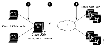
Network Configuration Scenario
The following table shows a tested deployment scenario for a single management server with the associated qualifying parameters.
Note
For example, 250 fully loaded Cisco AS5800 devices cannot be managed from a single server as this would exceed the 50,000 port limit.
About Excessive Incoming Traps
Excessive incoming traps may adversely affect Cisco UGM performance. If this occurs, evaluate incoming traps and disable those that are unnecessary (as shown in the following examples).
Examples of disabling incoming traps:
interface group-async0
no snmp trap link-statusinterface virtual-template 1
no snmp trap link-statusinterface dialer0
no snmp trap link-statusAbout Management Bandwidth
The following table and figure show the minimum bandwidth requirements for managing a 50,000 port network.
About Renaming Objects in Map Viewer
Cisco UGM allows you to rename objects in Map Viewer. However, the new name cannot contain any spaces. Any spaces in the object name affect system IOS operations.
If you assign an object name with spaces and then attempt to perform any IOS operation such as Get Configuration, Send Configuration, Install IOS Image, Install Modem Image, or Install SPE Image, Cisco UGM displays the following message in the IOS Action Report window:
Cannot connect, please check the user name and password.
Discovery and Deployment Caveats
This section contains information about the discovery and deployment function of Cisco UGM.
Deleting Manually Deployed Device Objects (DDTS:CSCdr48990)
Deleting a site object from the Physical view in Map Viewer does not delete the manually deployed device objects in the site object.
Automatically deployed device objects follow the site object/device object relationship. When you manually deploy device objects Cisco UGM does not create the site object, and device objects are deployed without a site. During normal operation, when you delete a site object, the device objects contained in that site are also deleted.
The following procedure describes how to manually deploy device objects, delete the site in which they are contained, and then verify that the device objects themselves are not deleted.
Step 1
Step 2
Step 3
Step 4
Step 5
Step 6
Step 7
Step 8
The devices in the deleted container object are listed.
Working Around the Condition
Step 1
Step 2
Caution
Device Objects Cannot be Created in Region and Bay Containers
(DDTS: CSCdt68717)If you deploy region and bay containers and attempt to deploy device objects in them, the deployment fails.
Working Around the Condition
Create only site containers and name them to represent different areas of your network.
Tips
Rediscovering Identical Cards in a Chassis (DDTS: CSCdv07469)
When a chassis containing two identical cards is deployed, and you insert a third identical card in a chassis slot, the rediscovery fails. The chassis transitions to an errored state and then a normal state. The internal cache in ASMainCtrl is not synchronized with the database, and Cisco UGM may behave erratically.
Working Around the Condition
If you have more than two cards of the same type installed in a chassis and wish to install a third card, follow these recommendations:
Step 1
Step 2
Step 3
Step 4
Note
Rediscovery Fails to Create New Objects (DDTS: CSCdv19501)
This condition can have several symptoms:
•
The workaround is to delete the device object and deploy it again. This erases all performance and alarm information for this device.
•
Rediscovery recreates the subcomponent objects, but all performance and alarm data for the objects is erased.
To work around this condition, export the performance data to file before changing the dial-shelf Id for the device. (Refer to the Cisco Universal Gateway Manager Users' Guide for details.)
•
The workaround is to always reboot the device in order to allow configuration changes to take effect.
•
There is no workaround for this condition.
Memory Leaks During Deployment and Deletion of Objects (DDTS: CSCdu01611)
During the deployment and deletion of subcomponent objects, memory leaks may occur. The memory loss is proportional to the number of subcomponent objects deployed or deleted. For every object that is either deployed or deleted, an estimated 64 bytes of memory are lost.
A symptom of this condition is the accidental exit (and restart) of the ASMainCtrl controller processes. Database corruption usually results from this condition.
Working Around the Condition
After large deployment operations, when your system is stabilized, stop and start Cisco EMF.
Note
Performance Management Caveats
This section contains information about the performance management function of Cisco UGM.
Correcting the Presentation of Performance Polling MIB Variables
(DDTS: CSCdt35957)To view the relevant MIB fields, follow this procedure:
Step 1
Step 2
Step 3
Step 4
Step 5
Step 6
Memory Poll Name
Memory Pool Name
ciscoPingRceivedPackets
ciscoPingReceivedPackets
Note
Missing Interface Data in Performance Polling File (DDTS: CSCds31288)
With the exception of Ethernet ports, other Cisco UGM-managed ports may not have all their data delivered to the performance data export file. This occurs because all relevant data is not always sent to the Cisco UGM system.
The ifTable in Cisco UGM is polled in order to monitor Ethernet port-related performance data. This data is then stored in the Cisco EMF database. Check the performance data export file to verify that Ethernet port-related information is always stored in the ifTable. However, in some cases other interface port data may be missing.
Note
Changing the Performance Polling ON/OFF Flag on a Powered-Down Device (DDTS: CSCdt30825)
To recreate the condition, follow this procedure:
Step 1
Step 2
Step 3
Step 4
Step 5
The following error message appears:
Nothing changed in the dialog, operation was discarded.
Cisco UGM only polls devices that are in a Normal state. Since the device was powered down, it is no longer Normal, and polling has already stopped on the device.
When you attempt to stop performance polling on the device, the error message conveys that your last action did not impact performance polling which was already stopped for the device.
Working Around the Condition
Note
You can check the current state of the device by following this procedure:
Step 1
Step 2
Step 3
The attribute value of CommonEM-MIB.controllerState is the current state of the device.
Performance Polling the First 500 Rows of Multi-Index Tables
(DDTS: CSCdv19475)When performance polling a large table of data, the poller uses a table chunker to split the table into 500-row chunks. Only the first chunk is retrieved successfully.
Working Around the Condition
You can manually change the related object model file and reset the Cisco EMF system as described:
Step 1
<CEMF_ROOT>/config/objectTypes/x_dASMainEM.types
Step 2
Step 3
Old:
"SNMP:CISCO-MODEM-MGMT-MIB.cmSlotIndex,
SNMP:CISCO-MODEM-MGMT-MIB.cmPortIndex"
New:
"SNMP:CISCO-MODEM-MGMT-MIB.cmPortIndex,
SNMP:CISCO-MODEM-MGMT-MIB.cmSlotIndex"
Step 4
Step 5
Step 6
Step 7
Caution
Step 8
Step 9
Fault Management Caveat
This section contains information about the fault management function of Cisco UGM.
Correcting the Description and Number of Alarms Displayed in the Event Browser (DDTS: CSCdt32217)
Note
To recreate the condition, follow this procedure:
Step 1
Step 2
Step 3
a.
Card removed from slot 7.
(Note the incorrect slot number in the message.)
b.
Card removed from slot 1.
Step 4
a.
Card inserted in slot 7.
(Note the incorrect slot number in the message.)
b.
Card inserted in slot 1.
c.
Card inserted in slot 1.
(This second informational message is redundant.)
Note
File Export Caveat
This section contains information about the file export function of Cisco UGM.
Exiting File Export Properties Window (DDTS: CSCdt29344)
The File Export Properties window exits when the Physical tree is empty. To recreate the condition, follow this procedure:
Step 1
Step 2
Step 3
An Action Report window appears with the message that the inventory data export file is created. The File Export Properties dialog box closes and the following error message appears:
Application Exiting, Connection has been lost to the Cisco EMF Manager platform.
Note
Note
Obtaining Documentation
Check for the most recent version of these release notes at this location:
http://www.cisco.com/univercd/cc/td/doc/product/rtrmgmt/ugm/relnote/ugm_note.htm
The following sections provide sources for obtaining documentation from Cisco Systems.
World Wide Web
You can access the most current Cisco documentation on the World Wide Web at the following sites:
•
•
•
Documentation CD-ROM
Cisco documentation and additional literature are available in a CD-ROM package, which ships with your product. The Documentation CD-ROM is updated monthly and may be more current than printed documentation. The CD-ROM package is available as a single unit or as an annual subscription.
Ordering Documentation
Cisco documentation is available in the following ways:
•
http://www.cisco.com/cgi-bin/order/order_root.pl
•
http://www.cisco.com/go/subscription
•
Documentation Feedback
If you are reading Cisco product documentation on the World Wide Web, you can submit technical comments electronically. Click Feedback in the toolbar and select Documentation. After you complete the form, click Submit to send it to Cisco.
You can e-mail your comments to bug-doc@cisco.com.
To submit your comments by mail, use the response card behind the front cover of your document, or write to the following address:
Attn Document Resource Connection
Cisco Systems, Inc.
170 West Tasman Drive
San Jose, CA 95134-9883We appreciate your comments.
Obtaining Technical Assistance
Cisco provides Cisco.com as a starting point for all technical assistance. Customers and partners can obtain documentation, troubleshooting tips, and sample configurations from online tools. For Cisco.com registered users, additional troubleshooting tools are available from the TAC website.
Cisco.com
Cisco.com is the foundation of a suite of interactive, networked services that provides immediate, open access to Cisco information and resources at anytime, from anywhere in the world. This highly integrated Internet application is a powerful, easy-to-use tool for doing business with Cisco.
Cisco.com provides a broad range of features and services to help customers and partners streamline business processes and improve productivity. Through Cisco.com, you can find information about Cisco and our networking solutions, services, and programs. In addition, you can resolve technical issues with online technical support, download and test software packages, and order Cisco learning materials and merchandise. Valuable online skill assessment, training, and certification programs are also available.
Customers and partners can self-register on Cisco.com to obtain additional personalized information and services. Registered users can order products, check on the status of an order, access technical support, and view benefits specific to their relationships with Cisco.
To access Cisco.com, go to the following website:
http://www.cisco.com
Technical Assistance Center
The Cisco TAC website is available to all customers who need technical assistance with a Cisco product or technology that is under warranty or covered by a maintenance contract.
Contacting TAC by Using the Cisco TAC Website
If you have a priority level 3 (P3) or priority level 4 (P4) problem, contact TAC by going to the TAC website:
http://www.cisco.com/tac
P3 and P4 level problems are defined as follows:
•
•
In each of the above cases, use the Cisco TAC website to quickly find answers to your questions.
To register for Cisco.com, go to the following website:
http://www.cisco.com/register/
If you cannot resolve your technical issue by using the TAC online resources, Cisco.com registered users can open a case online by using the TAC Case Open tool at the following website:
http://www.cisco.com/tac/caseopen
Contacting TAC by Telephone
If you have a priority level 1(P1) or priority level 2 (P2) problem, contact TAC by telephone and immediately open a case. To obtain a directory of toll-free numbers for your country, go to the following website:
http://www.cisco.com/warp/public/687/Directory/DirTAC.shtml
P1 and P2 level problems are defined as follows:
•
•
AccessPath, AtmDirector, Browse with Me, CCIP, CCSI, CD-PAC, CiscoLink, the Cisco Powered Network logo, Cisco Systems Networking Academy, the Cisco Systems Networking Academy logo, Fast Step, Follow Me Browsing, FormShare, FrameShare, GigaStack, IGX, Internet Quotient, IP/VC, iQ Breakthrough, iQ Expertise, iQ FastTrack, the iQ Logo, iQ Net Readiness Scorecard, MGX, the Networkers logo, Packet, RateMUX, ScriptBuilder, ScriptShare, SlideCast, SMARTnet, TransPath, Unity, Voice LAN, Wavelength Router, and WebViewer are trademarks of Cisco Systems, Inc.; Changing the Way We Work, Live, Play, and Learn, Discover All That's Possible, and Empowering the Internet Generation, are service marks of Cisco Systems, Inc.; and Aironet, ASIST, BPX, Catalyst, CCDA, CCDP, CCIE, CCNA, CCNP, Cisco, the Cisco Certified Internetwork Expert logo, Cisco IOS, the Cisco IOS logo, Cisco Press, Cisco Systems, Cisco Systems Capital, the Cisco Systems logo, Enterprise/Solver, EtherChannel, EtherSwitch, FastHub, FastSwitch, IOS, IP/TV, LightStream, MICA, Network Registrar, PIX, Post-Routing, Pre-Routing, Registrar, StrataView Plus, Stratm, SwitchProbe, TeleRouter, and VCO are registered trademarks of Cisco Systems, Inc. and/or its affiliates in the U.S. and certain other countries.
All other trademarks mentioned in this document or Web site are the property of their respective owners. The use of the word partner does not imply a partnership relationship between Cisco and any other company. (0108R)
Copyright © 2001, Cisco Systems, Inc.
All rights reserved.
![]()
![]()
![]()
![]()
![]()
![]()
![]()
![]()
Posted: Tue Dec 21 15:03:31 PST 2004
All contents are Copyright © 1992--2004 Cisco Systems, Inc. All rights reserved.
Important Notices and Privacy Statement.