|
|

This document describes how to connect and configure Gigabit Ethernet SwitchProbe devices.
These devices collect statistical information from an attached Gigabit Ethernet network segment or from the switched port analyzer (SPAN) port on a Cisco Catalyst-series switch.
You can use a Gigabit Ethernet SwitchProbe device to monitor:
The device is available in three models supporting 1000BaseLX or 1000BaseSX gigabit Ethernet:
Multi-mode fiber supports the propagation of multiple frequencies. Single-mode fiber has a higher bandwidth than multi-mode fiber, but requires a light source (such as a laser) with a narrow spectral width.
Depending on the type of cable used (MMF or SMF) and the distance the signal is transmitted, different laser types (LX or SX) may be used.
This document includes the following sections:
Command descriptions use the following conventions:
boldface font | Commands and keywords are in boldface. |
italic font | Arguments for which you supply values are in italics. |
[ ] | Elements in square brackets are optional. |
Screen examples use the following conventions:
| Terminal sessions and information the system displays are in |
boldface screen font | Information you must enter is in boldface screen font. |
[ ] | Default responses to system prompts are in square brackets. |
Notes use the following conventions:
Cautions use the following conventions:
 | Caution Means reader be careful. In this situation, you might do something that could result in equipment damage or loss of data. |
Warnings use the following conventions:
 | Warning This warning symbol means danger. You are in a situation that could cause bodily injury. Before you work on any equipment, you must be aware of the hazards involved with electrical circuitry and familiar with standard practices for preventing accidents. To see translated versions of the warnings, refer to the translated safety warnings appendix in the Cisco SwitchProbe Installation and Configuration Guide. |
The SwitchProbe device is designed to operate in a normal office environment and can be placed on a table, or mounted in an equipment rack near the network segment it serves. The site must be equipped with the following:
| Warning This product relies on the building's installation for short-circuit (overcurrent) protection. Ensure that a fuse or circuit breaker no larger than 120 VAC, 15A U.S. (240 VAC, 10A international) is used on the phase conductors (all current-carrying conductors). |
Before beginning the installation process, read the following installation cautions and warnings:
| Caution To prevent possible damage to the device, read the section "Site Requirements" in this document. |
| Warning The safety cover is an integral part of the product. Do not operate the unit without the safety cover installed. Operating the unit without the cover in place will invalidate the safety approvals and pose a risk of fire and electrical hazards. |
| Warning Read the installation instructions before you connect the system to its power source. |
| Warning Only trained and qualified personnel should be allowed to install, replace, or service this equipment. |
| Warning Ultimate disposal of this product should be handled according to all national laws and regulations. |
| Warning
The device is designed to work with TN power systems. |
| Warning Before working on a system that has an on/off switch, turn OFF the power and unplug the power cord. |
| Warning To prevent the device from overheating, do not operate it in an area that exceeds the maximum recommended ambient temperature of 104° F (40° C). To prevent airflow restriction, allow at least 3 inches (7.6 cm) of clearance around the ventilation openings. |
| Warning To prevent bodily injury when mounting or servicing this unit in a rack, you must take special precautions to ensure that the system remains stable. The following guidelines are provided to ensure your safety: |
Before unpacking the shipping carton, ensure that there is no visible damage to the carton. If there is damage, notify the carrier representative, and arrange for a representative to be present while you unpack the carton.
After opening the shipping carton and removing the unit, inspect it for any obvious damage that might have occurred during shipment. If any damage is present, file a claim with the carrier.
Inspect the shipping carton contents and verify that you have received the following:
This section describes the physical features of Gigabit Ethernet SwitchProbe devices.
Gigabit Ethernet SwitchProbe devices are housed in rack-mountable, front-access chassis that measures 17 inches wide, by 16.5 inches deep, by 5.25 inches high (43.18cm wide by 41.91cm deep by 13.34cm high). You can mount these devices in a 19-inch equipment rack. For instructions on mounting the device in a rack, see the installation chapter in the Cisco SwitchProbe Installation and Configuration Guide.
The following sections describe each area of the Gigabit Ethernet SwitchProbe devices:
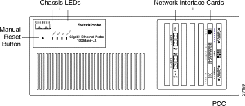
Figure 1 shows the front panel of the Gigabit Ethernet SwitchProbe 1000BaseLX model. Figure 2 shows the front panel of the Gigabit Ethernet SwitchProbe 1000BaseSX model.

The following sections describe the elements on the front panel of the Gigabit Ethernet SwitchProbe devices:
Table 1 describes the four LEDs on the top left of the chassis front panel.
| LED Label | LED Color | Status | Meaning |
|---|---|---|---|
POWER | Green | On | Proper power is being supplied to the device. This LED is normally on. |
Off | Proper power is not being supplied to the device. | ||
FAULT | Red | On or | Hardware or software error in the device. |
Off | Device is working properly. | ||
|
| Reserved for future diagnostic use. | |
ACTIVITY | Amber | On | Heavy network traffic. |
| Blinking | Moderate network traffic. | |
Off | No network traffic. | ||
There is a small pin hole (Figure 1) to the left of the LEDs that provides access to the manual reset button. To manually reboot the device, insert a small object such as the tip of a pen, and push inward. A slight press of the manual reset button reboots the device.
The following sections describe the interfaces on the Gigabit Ethernet 1000BaseLX and 1000BaseSX SwitchProbe devices:
Gigabit Ethernet 1000BaseLX and 1000BaseSX devices contain the following two network interface cards (NICs).
Table 2 describes the interfaces on Gigabit Ethernet SwitchProbe 1000BaseLX models.
| Interface Number | Interface Type | Connection Type | Default Interface Mode |
|---|---|---|---|
1 | Ethernet | Thicknet (10Base5) | Manage |
2 | Serial | Remote (DB-9) port | Manage |
| Note Interface number depends on mode configured. See "Connecting a Gigabit Ethernet SwitchProbe Device to the Network." 3 (half-duplex mode) Interface 3—port 2 Interface 4—port 1 | Gigabit Ethernet LX | SC-type (fiber optic) | Monitor only |
3 (full-duplex mode, default) |
|
|
|
Table 3 describes the interfaces on the Gigabit Ethernet SwitchProbe 1000BaseSX model.
| Interface Number | Interface Type | Connection Type | Default Interface Mode |
|---|---|---|---|
1 | Ethernet | Thicknet (10Base5) | Manage |
2 | Serial | Remote (DB-9) port | Manage |
| Note Interface number depends on mode configured. See "Connecting a Gigabit Ethernet SwitchProbe Device to the Network." 3 (half-duplex mode) Interface 3—port 2 Interface 4—port 1 | Gigabit Ethernet SX | SC-type (fiber optic) | Monitor only |
3 (full-duplex mode, default) |
|
|
|
The Peripheral Controller Card (PCC), always designated as interface 2, has the following three external components:
To adjust the baud rate of the remote port, see the Cisco SwitchProbe Installation and Configuration Guide.
Table 4 shows the console and remote port specifications.
| Port Setting | Specification |
|---|---|
Line rate | 9600 bps (default) |
Line code | ASYNC |
Line interface | EIA/TIA-232 |
No. of bits | 8 |
No. of stop bits | 1 |
Parity | None |
| Switch | Setting | Result |
|---|---|---|
1 | Off (default) | Boot from FLASH memory |
2 | Off (default) | Reserved |
3, 4 | 3 = off | Console port = 1200 bps |
3 = off | Console port = 2400 bps | |
3 = on (default) | Console port = 9600 bps | |
3 = on | Console port = 19200 bps |
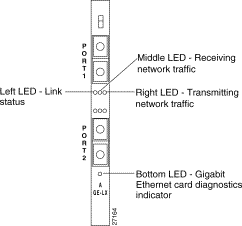
Each Gigabit Ethernet interface contains seven LEDs:
Table 6 describes the Gigabit Ethernet interface LEDs.
| LED Position | LED Color | Status | Meaning |
|---|---|---|---|
Left LED | Green | On | Link signal detected. |
Off | No link signal detected or no cable attached to port. | ||
Middle LED | Yellow | On | Receiving heavy network traffic. |
Blinking | Receiving moderate network traffic. | ||
Off | Receiving no network traffic. | ||
Right LED | Green | On | Transmitting heavy network traffic. |
Blinking | Transmitting moderate network traffic. | ||
Off (default) | Transmitting no network traffic. This LED is always off when interfaces are configured to monitor. | ||
Bottom LED | Yellow | On | Gigabit Ethernet card diagnostics are complete. |
Off | Gigabit Ethernet card is not functioning properly or diagnostics not yet complete. |
Figure 3 shows the Gigabit Ethernet interface LEDs.
The Ethernet interface contains two LEDs, described in Table 7.
| LED Position | LED Color | Status | Meaning |
|---|---|---|---|
Left LED | Green | On | Link signal detected. |
Right LED
| Amber | On | Heavy network traffic. |
Figure 4 shows the Ethernet interface LEDs.

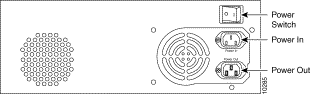
Figure 5 shows the rear panel of a Gigabit Ethernet SwitchProbe device.
The following sections describe each area on the rear panel of the Gigabit Ethernet SwitchProbe devices:
There are two power sockets on the rear panel of the Gigabit Ethernet SwitchProbe device:
| Caution To prevent damage to the device, and to ensure that it operates correctly, never use the Power Out socket. |
Each Gigabit Ethernet SwitchProbe device is equipped with an AC power cord for connection to an appropriate power source. To connect the device to a power source, see "Connecting a Gigabit Ethernet SwitchProbe Device to a Power Source."
The power switch is on the upper right of the rear panel of the device. To turn on the power, press the (|) side of the button until it is flush with the rear panel. To turn off the power, press the (0) side of the button until it is flush with the rear panel.
| Caution To avoid damaging the device, you cannot turn the power off for four seconds after you turn the power on. |
Before connecting this device to the network, note the following warnings:
| Warning This equipment is to be installed and maintained by service personnel only as defined by AS/NZS 3260 Clause 1.2.14.3 Service Personnel. |
| Warning The telecommunications lines must be disconnected 1) before unplugging the main power connector and/or 2) while the housing is open. |
| Warning Do not work on the system or connect or disconnect cables during periods of lightning activity. |
To connect a Gigabit Ethernet SwitchProbe device to the network segment, see the following sections:
The Ethernet interface supports either Thicknet, Thinnet, or unshielded twisted pair (UTP) cable types; the device is set to one of the three types during manufacture. A label in the lower portion of the device front panel indicates the factory-set configuration.
Table 8 describes the label and corresponding connection.
| If the Label States... | You Connect |
|---|---|
Configured for AUI | A Thicknet (10Base5) cable to the Thicknet connector. |
Configured for BNC | A Thinnet (10Base2) cable to the Thinnet connector. |
Configured for UTP | A UTP cable to the RJ-45 UTP connector. |
The way you connect the Gigabit Ethernet interface to a network segment depends on the type of segment to be monitored.
Some switches (such as the Cisco Catalyst 4000-, 5000, and 6000-families) have an auto-negotiate mode that allows a port on the switch to automatically negotiate the speed and mode (half- or full-duplex) of the device on the other side of the network segment. If the other side of the segment (for example, the Gigabit Ethernet SwitchProbe device) does not respond to the auto-negotiation, the switch assumes that there is no device at the other end, and shuts off the internal link.
Because this SwitchProbe device is designed to work in receive-only mode, it does not participate in any auto-negotiation in half-duplex mode. Therefore, the switch assumes there is no device attached to the other end of the network segment—even though the Gigabit Ethernet SwitchProbe device is physically attached to the switch SPAN port.
To work around this, you must disable auto-negotiation on the port to which the Gigabit Ethernet SwitchProbe device is physically connected.
For example, with a Cisco Gigabit Ethernet switch, you would enter the following command on the switch command line:
set port negotiation module_num/port_num disable
where module_num/port_num identifies the port on the switch that is connected to the Gigabit Ethernet SwitchProbe device.
This situation occurs only when a Gigabit Ethernet SwitchProbe device is directly attached (with no tap) to a Cisco Catalyst-series switch SPAN port.
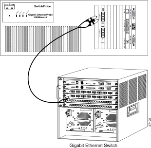
To connect the Gigabit Ethernet interface to a Cisco Catalyst-series switch, see Figure 6 and follow these steps:
Step 1 Locate an SC-to-SC fiber cable (with one male SC connector at each end) that was included with the SwitchProbe device.
Step 2 Remove all dust caps from the connectors at the ends of the cable.
Step 3 Plug one end of the SC-to-SC fiber cable into the Gigabit Ethernet switch, server, or router to be monitored.
Step 4 Plug the other end of the cable into one of the Gigabit Ethernet interface ports on the SwitchProbe device.
Connecting the Gigabit Ethernet interface to a full-duplex network segment is a two-stage process:
Step 1 Connecting the fiber optic splitter tap (shipped with the device) to the Gigabit Ethernet interface on the SwitchProbe device.
Step 2 Connect two Gigabit Ethernet devices to the fiber optic splitter tap (to accumulate statistics about data as it travels on the network segment).
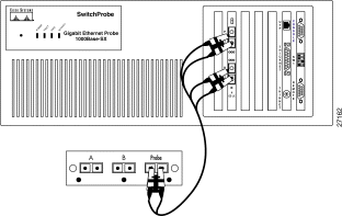
To connect a fiber optic splitter tap to the SwitchProbe device, see Figure 7 and follow these steps:
Step 1 Remove all dust caps from the fiber optic splitter tap connector ports.
Step 2 Locate the 9.84 foot (3 meter) fiber cable (with two male SC connectors at one end and one male SC connector at the other end) that was included with the tap.
Step 3 Remove all dust caps from the connectors at the ends of the cables.
Step 4 Plug the end of the fiber cable (labelled DCE) into port 1 of the Gigabit Ethernet interface (port 1 is the DCE port).
Step 5 Plug the end of the fiber cable (labelled DTE) into port 2 of the Gigabit Ethernet interface (port 2 is the DTE port).
Step 6 Plug the other end of the fiber cable (the one with a single connector) into the port labelled Probe on the fiber optic splitter tap.
After you connect the Gigabit Ethernet interface on the SwitchProbe device to the tap, you must connect the tap to the network segment.
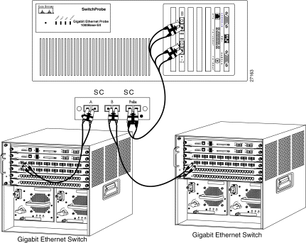
To do so, see Figure 8 and follow these steps:
Step 1 Locate the cable that currently connects one Gigabit Ethernet switch, server, or router to another Gigabit Ethernet switch, server, or router.
Step 2 Unplug this cable from one of the two Gigabit Ethernet devices.
Step 3 Plug the end of the cable (that you just unplugged) into the one of the two remaining female SC duplex ports on the tap (either port A or B).
Step 4 Locate an SC-to-SC fiber cable (with one male SC connector at each end).
Step 5 Plug one end of the SC-to-SC fiber cable into the second Gigabit Ethernet switch, server, or router.
Step 6 Plug the other end of the cable into the remaining female SC duplex port on the tap (A or B).
As illustrated in Figure 8, there should now be one cable extending from one Gigabit Ethernet switch, server, or router to the tap A port, and another cable from another Gigabit Ethernet switch, server, or router to the tap B port, and the tap should be connected to the SwitchProbe device.
To connect a Gigabit Ethernet SwitchProbe device to a power source, follow these steps:
Step 1 Using the AC power cord included with the device, connect one end of the cord to the Power In socket.
| Warning This equipment is intended to be grounded. Ensure that the host is connected to earth ground during normal use. |
Step 2 Connect the other end of the AC power cord to a suitable power source.
| Caution To prevent any possible damage to the device, and to ensure that it operates correctly, never use the Power Out socket. |
The Cisco SwitchProbe Installation and Configuration Guide (shipped with all Cisco SwitchProbe devices) explains the basic configuration process. Read and follow the instructions in that guide to configure the agent firmware in your SwitchProbe device.
When you choose Select Probe Mode from the Agent Configuration Utility main menu (selection 23), two options (half- and full-duplex) are displayed in another menu. You use these options to set the mode on the Gigabit Ethernet NIC. The default value is full-duplex (1).
To select the mode, follow these steps:
Step 1 From the Select Probe Mode menu, enter the option number (1 for half-duplex or 0 for full-duplex) and press Enter.
The Agent Configuration Utility main menu is displayed.
Step 2 Enter the number listed to the left of the Reset Agent menu option and press Enter.
For more information about resetting the agent, see the Cisco SwitchProbe Installation and Configuration Guide.
In earlier releases of the agent firmware, the aging algorithm would age out (delete) host and conversation entries when the aging_interval had elapsed. If a host table was full, no additional hosts would be counted until the next time the aging_interval elapsed.
The aging algorithm in the Gigabit Ethernet SwitchProbe device firmware has been modified to manage noise (non-critical) nodes in the hosts and conversation tables, freeing up space in the host and conversation tables. By doing so, the host and conversation tables can contain the more critical host and conversation data.
To implement the modified aging algorithm, you must assign values to three aging parameters:
The removal of any node from the host or conversation table occurs only when one of these conditions exists:
For example, if the aging parameters are set to the following values, and the node sends a ping packet every 300 seconds, the node is initially seen in the host table:
However, because the node does not send more than 3000 bytes during a 300-second interval, upon reaching the min_aging period of 10800 seconds (three hours), the node is deleted from the host table.
If, after one hour, the same node sends an FTP data packet at a rate of 10,000 bytes in 300 seconds, then resumes a ping process at a rate of 64 bytes every 300 seconds—but during the next three hour period sees data at a rate that is less than 3,000 bytes in a 300-second interval—then, upon reaching the min_aging period of 10800 seconds (three hours) since the FTP data packet passed through, the node is deleted from the host table.
The noise_threshold check determines whether any node has sustained minimum traffic within the min_aging period.
Table 9 describes the aging parameters.
| Parameter | Description |
|---|---|
min_aging | The number of seconds that a node containing noise can occupy the host/conversation table. Upon reaching the min_aging period, a node containing noise is deleted. Values range from 300 (default) to 86400 seconds (5 minutes to 24 hours). |
age_check_interval | The frequency (in seconds) at which the aging algorithm is invoked. Values range from 300 (default) to 21600 (5 minutes though 6 hours). |
noise_threshold | The minimum number of bytes that should be seen at each age_check_interval to distinguish the node as vital versus noisy. If the node does not meet this minimum setting, it is considered to contain noise and is deleted from the host/conversation table when the next min_aging period expires. Values range from 0 (default, causing the aging algorithm to never check for noise) to 10000. |
Table 10 lists technical specifications for the Gigabit Ethernet SwitchProbe device.
Standards compliance for all SwitchProbe devices is as follows:
| Item | Specification | |
|---|---|---|
Power consumption | 250W maximum | |
Power input | 100-115/220-240 /VAC, 7/4 A, 50-60 Hz (auto-switching) | |
Operating temperature | 32º to 104ºF (0º to 40ºC) | |
Storage temperature | -40º to 140ºF (-4º to 60ºC) | |
Humidity | 5% to 95% rel. humidity (noncondensing) | |
Dimensions | 5.25 x 17 x 16.5 in. (excluding 1 in.-wide rack-mount clips) | |
Weight | 24 pounds (10.89kg) | |
Memory | ||
| RAM | 64 MB |
Port type |
| |
| Ethernet | DB15 10Base5 (Thicknet) |
| Console and remote | Connector style—DB-9 male connector |
| Gigabit Ethernet | SC-type connector (fiber optic) |
Network management standards
| SNMP V1 | |
Manage/monitor interfaces and available modes | Interface 1, Ethernet—Mode: Manage | |
The following sections describe the cable pinouts:
Table 11 describes the pin designations for the Ethernet AUI Interface.
| Pin | Signal Name | Direction |
|---|---|---|
1 | Logic Ground | (GND) |
2 | Collision Input+ (CI+) | In |
3 | Transmit Data+ (DO+) | Out |
4 | Logic Ground | (GND) |
5 | Receive Data+ (DI+) | In |
6 | +12V Logic Ground | (GND) |
7 | Not used |
|
8 | Logic Ground | (GND) |
9 | Collision Input- (CI-) | In |
10 | Transmit Data- (DO-) | Out |
11 | Logic Ground | (GND) |
12 | Receive Data- (DI-) | In |
13 | +12V Power (+12) | Out |
14 | Logic Ground | (GND) |
15 | Not used |
|
Table 12 shows the EIA/TIA-232 pin designations for the console and remote serial ports.
Cisco Connection Online (CCO) is Cisco Systems' primary, real-time support channel. Maintenance customers and partners can self-register on CCO to obtain additional information and services.
Available 24 hours a day, 7 days a week, CCO provides a wealth of standard and value-added services to Cisco's customers and business partners. CCO services include product information, product documentation, software updates, release notes, technical tips, the Bug Navigator, configuration notes, brochures, descriptions of service offerings, and download access to public and authorized files.
CCO serves a wide variety of users through two interfaces that are updated and enhanced simultaneously: a character-based version and a multimedia version that resides on the World Wide Web (WWW). The character-based CCO supports Zmodem, Kermit, Xmodem, FTP, and Internet e-mail, and it is excellent for quick access to information over lower bandwidths. The WWW version of CCO provides richly formatted documents with photographs, figures, graphics, and video, as well as hyperlinks to related information.
You can access CCO in the following ways:
For a copy of CCO's Frequently Asked Questions (FAQ), contact cco-help@cisco.com. For additional information, contact cco-team@cisco.com.
![]()
![]()
![]()
![]()
![]()
![]()
![]()
![]()
Posted: Fri Sep 6 20:20:36 PDT 2002
All contents are Copyright © 1992--2002 Cisco Systems, Inc. All rights reserved.
Important Notices and Privacy Statement.