This chapter describes how to install, configure, and start NSP. Before installing NSP, ensure that the steps described in the "Preparing to Install Native Service Point" chapter have been completed.
This chapter provides information on the following:
The following is a list of the tasks that must be completed when installing and configuring NSP. The procedure for completing each task follows this summary.
- Upload the NSP data sets to the MVS host
- Convert the NSP data sets to partitioned data sets
- Modify SOLVE:Netmaster data sets for NSP
- Start the NSP setup and configure the NSP management environment
- Create an NSP administrator profile
After completing these tasks, you can migrate existing router definitions if you are using NSP Version 1.0 and initialize NSP.
This section contains information on the following:
While the NSP files can be uploaded using different methods, NSP provides an installation utility that automatically uploads the NSP compressed files to an MVS host in binary format to data sets that have a fixed block (FB) record format (RECFM) and 80-byte record size (LRECL). The NSP installation utility uses the SEND command supported by the IBM Communications Manager/2 Release 1.11 or later running on IBM Operating System/2 (OS/2).
If you are not installing from OS/2 using Communications Manager/2, use the upload utility available with your TN3270 package and ensure that the NSP files are uploaded with a FB, RECFM, and LRECL=80 file format. This is the required format in which the NSP files must be uploaded to convert them to partition data sets during the NSP installation.
 | Caution Using File Transfer Protocol (FTP) to upload the NSP compressed files to am MVS host is not recommended. Complications could develop with producing the proper file format. |
To upload the NSP files to an MVS host from OS/2:
Step 1 Start a TN3270 session and log in to TSO.
Step 2 On the TSO main menu panel, type 6 in the Select Option field and press Enter. The TSO Command Processor panel is displayed.
Step 3 Insert NSP disk 1 into the disk drive of your PC.
Step 4 At the OS/2 command prompt, type the letter representing the drive in which the NSP disk is located and press Enter.
Step 5 At the OS/2 command prompt, type the following command and press Enter:
nspulod1 local_disk host_session prefix
Where:
- local_disk is the drive in which the NSP disk is located
- host_session is the host emulator session ID
- prefix is the file prefix, if your system requires a prefix (the NSP default prefix is your TSO ID). If the TSO User ID option is on, do not specify a value for this argument.
Step 6 When the upload process is complete, insert NSP disk 2 into the disk drive of your PC.
Step 7 At the OS/2 command prompt, type the following command and press Enter:
nspulod2 local_disk host_session prefix
Where:
- local_disk is the drive in which the NSP disk is located
- host_session is the host emulator session ID
- prefix is the file prefix, if your system requires a prefix (the NSP default prefix is your TSO ID). If the TSO User ID option is on, do not specify a value for this argument.
Step 8 When the upload process is complete, verify that the NSP files uploaded to the MVS host by returning to your TSO session. On the TSO main menu, type 3.4 in the Select Option field, and press Enter. The Data Set List Utility panel is displayed.
Step 9 In the DSNAME LEVEL field, type userid.nsp* (where userid is your TSO ID or system prefix) and press Enter. The following NSP data sets should be listed on the DSLIST panel:
- NETMNCL1.SEQ
- NETMNCL2.SEQ
- NETMPNLS.SEQ
- NETMSAMP.SEQ
Once you have uploaded the NSP data sets to the MVS host, you must convert the NSP data sets to partitioned data sets.
To convert the NSP data sets to partitioned data sets:
Step 1 On the DSLIST panel, position the cursor in the Command column to the left of the first data set (NETMNCL1.SEQ).
Step 2 Type receive inds (/) and press Enter.
Step 3 When prompted, press Enter. The partitioned data set should be created.
If the receive command is terminated, type an S in the command column to the left of the data set to display details about the data set. From the data set details, verify that the data set was uploaded to the MVS with an F or FB record format and a record size of 80.
If these values are correct, type a B in the command column to the left of the data set to browse the NSP data set. The data should be skewed but readable. If you cannot read the data, then either an ASCII or CRLF format may have been used to upload the data set.
If these formats were used, repeat the upload procedure as described in the "Uploading the NSP Files" section and ensure that the proper format is used.
Step 4 Press Tab to move to the next file, type receive inds (/), and press Enter.
Step 5 When prompted, press Enter.
Step 6 Repeat Steps 4 and 5 for the remaining NSP data sets.
Step 7 When you have completed converting the NSP data sets to partitioned data sets, press F3 to return to the Data Set List Utility and then press Enter. The DSLIST panel is displayed with a refreshed list of data sets.
In addition to the first four NSP data sets, the list should now include the following data sets:
- NETMV1R2.NSPNCL1
- NETMV1R2.NSPNCL2
- NETMV1R2.NSPPNLS
- NETMV1R2.NSPSAMP
This section describes the modifications that need to be made to the SOLVE:Netmaster data sets to use NSP.
Note It is recommended that an MVS programmer complete the following procedures.
To modify the SOLVE:Netmaster data sets for NSP:
Step 1 Copy each of the members from the NETMV1R2.NSPNCL1 and NETMV1R2.NSPNCL2 data sets to the COMMANDS data set (located in the SOLVE:Netmaster PROC).
Step 2 NSP uses the SOLVE:Netmaster user panel library. If you do not have an existing user panel library, create one by opening the SOLVE:Netmaster NMINIT member (located in the COMMANDS data set in the SOLVE:Netmaster PROC) and change the PANLUSR variable to YES.
Step 3 Open the PNLRESTR member (located in the NETMV1R2.NSPSAMP data set) and change the DSN values in the following statements for local use:
//PNLS DD DSN=NETMASTR.V3101.PANLUSR, DISP=SHR
//PNLSIN DD DSN=userid.NETMV1R2.PNLBCKUP, DISP=OLD
Where:
- netmaster is the data set you created in Step 2.
- userid is you TSO ID or system prefix.
Step 4 Submit the PNLRESTR member to restore the panels to the SOLVE:Netmaster PANLUSR data set and then verify that the job successfully completed.
Step 5 Copy the $NWRUNCM procedure set (located in the SOLVE:Netmaster NSTEXEC data set) to the COMMANDS data set (located in the SOLVE:Netmaster PROC) and name it $NWRUNCX.
Step 6 Open the NMMODS member (located in the NETMV1R2.NSPSAMP data set) and use the provided directions and statements to modify the $NWRUNCX procedure.
Note Ensure that you use the sequence numbers as referenced in the NMMODS member.
Step 7 Open each of the following members (located in the NETMV1R2.NSPSAMP data set) and replace each occurrence of the dddddd argument and the prefix argument with the appropriate volume serial number and prefix:
These members create the VSAM data sets used by NSP.
Step 8 If you are using CiscoWorks Blue SNA View, open the ALLHISTR member (in the NETMV1R2.NSPSAMP data set) and replace each occurrence of the dddddd argument and the prefix argument with the appropriate volume serial number and prefix.
Step 9 Submit each of the members that you edited in Steps 8 and 9.
Step 10 Open the NMUDB member (located in the NETMV1R2.NSPSAMP data set) and verify that the data set definition names match those allocated by the ALLCFG, ALLHISTC, ALLHISTI, and ALLHISTR members.
Step 11 Copy the NMUDB member (located in the NETMV1R2.NSPSAMP data set) into the SOLVE:Netmaster NMINT member (located in the COMMANDS data set in the SOLVE:Netmaster PROC).
Step 12 Restart SOLVE:Netmaster.
To enable NSP to automatically obtain and provide an updated status of your Cisco routers, open the MSGPROC member located in the NSPV1R2.SAMPLIB data set, copy the following statements, and insert them into the SOLVE:Netmaster MSGPROC member located in the COMMANDS data set in the SOLVE:Netmaster PROC.
To enable automatic status update:
Step 1 Open the NMMSGS member (located in the NETMV1R2.NSPSAMP data set) and copy and add the following statements to the SOLVE:Netmaster MSGPROC member (located in the COMMANDS data set in the SOLVE:Netmaster PROC) for the operator who will receive the VTAM messages.
.M#IST093I
.M#5A93I
&NODE = &STR &2 -* SAVE THE NODE Name
NSPRVDIS &NODE
&GOTO .LOOP -* NEXT MESSAGE
.M#IST105I
-*.M#5B05I
&NODE = &STR &2 -* SAVE THE NODE Name
NSPRVDIS &NODE
&GOTO ..LOOP -* NEXT MESSAGE
.M#IST590I
.M#5D90I
&NODE = &STR &6 -* SAVE THE NODE Name
&NODECONN = &STR &2 -* GET THE NODE Status
NSP590E &NODE &NODECONN
&GOTO .LOOP -* NEXT MESSAGE
OR
If the any of these statements already exists in the procedure, do not copy and add the above statement, but instead add the following statement after each of the existing labels.
&NODE = &STR &5 -* SAVE THE NODE Name
&NODECONN = &STR &2 -* GET THE NODE Status
RTR590E &NODE &NODECONN -* Call Update Status
Step 2 If you are using CiscoWorks Blue SNA View, copy the following statement to automatically obtain updated status for NSP SNA View RIF processing:
.M#ISTEXCCS
&NODE = &STR &6 -* SAVE THE NODE Name
NSPSRIF &NODE
&GOTO .LOOP -* NEXT MESSAGE
Step 3 Save and exit the member.
This section contains information on the following:
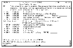
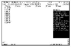
To start the NSP setup, from the SOLVE:Netmaster Command Entry panel command line, type nsp, and press Enter. The NSP Main Menu panel is displayed.
Figure 3-1: NSP Main Menu
Before starting NSP, you must define the NSP management environment and create an NSP administrator profile.
Defining the management environment includes specifying:
- Which NSP applications you want to use
- What types of interfaces you want to monitor
- At what intervals you want NSP to monitor routers and interfaces
- What CPU and memory performance thresholds you want to set
The first NSP operator profile is, by default, an NSP administrator profile. This ensures that after you have configured and started NSP, the existing operator profile is authorized to configure and maintain the NSP management environment and assign authority levels to other user's operator profiles that dictate the NSP actions that user can perform.
NSP administrators can be either an enabled or disabled user. An enabled user is an operator who is authorized to log in to a router in enable mode and issue control and configuration commands to the router.
A disabled NSP administrator can:
- Create operator profiles and assign user authority
- Configure and change the NSP management environment
An enabled NSP administrator can:
- Issue the Cisco IOS software enable command and issue commands that control and configure Cisco routers
- Add, modify, and delete router and DSPU resource definitions
- Modify interface settings
To define the NSP management environment and administrator profile:
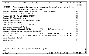
Step 1 On the NSP main menu, position the cursor on the * SETUP option and press Enter. The NSP Router Management Setup panel is displayed.
Figure 3-2: NSP Router Management Setup Panel
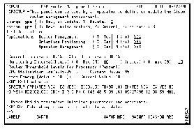
The following information is displayed on the NSP Router Management Setup panel:
- Last Initialized--Date and time when NSP was last started.
- Current Interval--Current setting for router monitoring. Because NSP Version 2.0 has not yet been started, this field is blank.
- Stored Interval--Interval setting stored in VTAM. Because NSP Version 2.0 has not yet been started, this field is blank.
- VSAM KSD Contents--Details of the VSAM data record containing the NSP configuration data. Because NSP Version 2.0 has not yet been started, this field is blank.
Step 2 Specify information in the following fields:
- Change Type--Indicates whether you are defining the management environment for the first time, changing an existing setup, or deleting a setup. Type 1 to specify that you are defining the NSP management environment for the first time.
- Action Type--Indicates whether you want to implement your changes at the next startup of NSP, implement them in the current session only, or implement them in the current session and save the changes for future sessions. Type 3 to specify that you want to save the changes for the future sessions.
- Applications--NSP applications you want to use. Type Y to the right of each application you want to use. Type N to the right of each application you do not want to use.
- Monitoring Intervals (Hours)--Interval, in hours, that you want NSP to monitor and collect status information from routers. Valid range is 1 to 24 hours. If you specify a monitoring interval in this field, do not specify a monitoring interval in the Minutes field.
- Monitoring Intervals (Minutes)--Interval, in minutes, that you want NSP to monitor and collect status information from routers. Valid range is 15 to 59 minutes. If you specify a monitoring interval in this field, do not specify a monitoring interval in the Hours field.
- Router Thresholds (CPU and Memory)--Percentage of the router CPU and memory that when exceeded alters the status of a router on the Router Status panel. Valid range is any 2-digit numeric value. To stop measuring the CPU performance, specify 00 in the CPU field.
Step 3 To view and specify interface monitoring settings, press F8. The NSP monitoring setup parameters are displayed.
Figure 3-3: Interface Monitoring Setup Parameters Panel
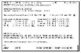
The following information is displayed on this panel:
- Interface Monitoring Interval, Current Interval--Current setting for interface monitoring. Because NSP Version 2.0 has not yet been started, this field is blank.
- Interface Monitoring Interval, Stored Interval--Interval setting stored in VTAM. Because NSP Version 2.0 has not yet been started, this field is blank.
- VSAM KSD Contents--Details of the VSAM data record containing the NSP configuration data. Because NSP Version 2.0 has not yet been started, this field is blank.
Step 4 Specify information in the following fields:
- Monitoring Interval (Hours)--Interval, in hours, that you want the performance information and the status of monitored interfaces updated. Valid range is 1 to 24 hours. If you specify a monitoring interval in this field, do not specify a monitoring interval in the Minutes field.
- Monitoring Interval (Minutes)--Interval, in minutes, that you want the performance information and the status of monitored interfaces updated. Valid range is 15 to 59 minutes. If you specify a monitoring interval in this field, do not specify a monitoring interval in the Hours field.
- Interfaces to be monitored--Types of interfaces that you want NSP to monitor. To specify for NSP to monitor an interface, type Y in the field to the right of the interface. To specify for NSP not to monitor an interface, type N.
Step 5 To view NSP defaults for database constants, variables, and wrap counts, press F8. The Router Management Constants Setup panel is displayed.
Step 6 To display the common globals used by NSP, press F10. The NSP Common Globals panel is displayed.
| Caution The database IDs on this panel can only be modified before initializing NSP. |
Step 7 Press F3 to return to the NSP Management Constants Setup panel and press F4 to save and exit the NSP Router Management setup. The Cisco Router User Administration panel is displayed.
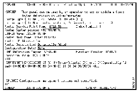
Figure 3-4: Cisco Router User Administration Panel
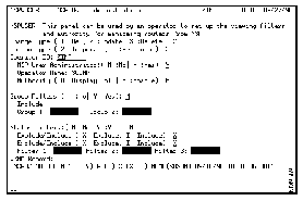
The following information is displayed on the Cisco Router User Administration panel:
- Operator ID--ID of the operator whose profile is being created. It should display your user ID.
- VSAM Record--Details of the VSAM data record containing the NSP configuration data.
Step 8 Specify information for the following fields:
- Change Type--Indicates whether you are defining a new operator profile, changing an existing profile, or deleting the profile. Type 1 to specify that this is a new operator profile.
- Action Type--Indicates whether you want to implement your changes at the next startup of NSP, implement them in the current session only, or implement them in the current session and save the changes for future sessions. Type 3 to specify that you want to save the changes for future sessions.
- NSP User Administrator--Indicates whether this operator is an NSP administrator. Type Y to specify the operator profile is for an NSP administrator.
- Operator Name--Name of the user assigned to the user ID. Type your name in this field.
- Authority--Indicates whether the operator can only view information or can enable a router and perform router management functions. Type an E to specify that you are an enabled user.
- Group Filters--Logical groups by which you may want to filter routers. To enable group filtering, type a Y to the right of the Group Filters field. In the Group 1 and Group 2 fields, type one or two logical groups by which you want to filter routers.
- Logical groups are defined by an NSP administrator in the router definition for filtering purposes. The logical group or groups to which a router may belong are displayed on the Router Status Extended panel.
- For more information on filtering routers, see the "Filtering Routers" section of the "Monitoring Routers" chapter.
- Status Filters--Status by which you want to filter routers. To enable status filtering, type a Y to the right of the Status Filters field. Type an X or I to the right of the Exclude/Include field to indicate whether you are filtering to include or exclude routers that match a status. In the Filter 1, Filter 2, and Filter 3 fields, type one to three statuses by which you want to filter routers.
- For more information on filtering routers, see the "Filtering Routers" section of the "Monitoring Routers" chapter.
Step 9 When you have completed the administrator profile, press Enter to verify the changes and then F4 to save the profile.
NSP provides a migration utility that allows you to migrate existing NSP Version 1.0 router definitions to NSP Version 2.0.
To migrate your existing NSP Version 1.0 router definitions:
Step 1 From a SOLVE:Netmaster Command Entry panel command line, type nspsinit reset and press Enter. The NSP Common Globals panel is displayed.
Step 2 Start NSP Version 1.0 by typing nspsinit and pressing Enter.
Step 3 Type nsprmgrt and press Enter. As NSP collects the interface data for each router that was defined to NSP Version 1.0, the following message is displayed where ROUTER_NAME is the name of the router whose definition is being migrated:
NSP1081I NOW COLLECTING INTERFACE DATA FOR ROUTER ROUTER_NAME.
When all the NSP Version 1.0 router definitions have been migrated to NSP Version 2.0, the following message is displayed:
NSPRMGRT MIGRATION FROM NSP R1 TO NSP R2 COMPLETE.
The NSP program is designed to be started and left running so that your Cisco routers, interfaces, and DSPU and CIP resources are being monitored at all times.
To have NSP automatically start when SOLVE:Netmaster starts, open the NMREADY member (located in the COMMANDS data set in the SOLVE:Netmaster PROC), and add the following command:
sub bmon nspinit
The following sections provide general information about using the NSP main menu, panels, and function keys.
This section explains the NSP main menu, describes the NSP applications available on the NSP main menu, and describes how to access each of those applications.
To access the NSP main menu:
Step 1 From a SOLVE:Netmaster command prompt, type nsp and press Enter. The NSP main menu is displayed.
Figure 3-5: NSP Main Menu
The following applications are available on the NSP main menu:
- MGR--Primary router management application. Select the * MGR option to display the status of the routers being managed by NSP.
- USER--User profile application. Select the * USER option to create or modify an operator profile. Also select the * USER option to define filters for viewing routers.
- CMD--Router command interface. The router command interface application enables you to connect to and issue commands directly to a router and receive responses from the router.
- IDIS--Cisco router interface status list application. Use the Cisco router interface status list application to display, in summary, the status of all of a type of interface enabled in the routers on your network. Using the router interface status list applications, you can obtain additional information about an interface.
- SETUP--NSP router management setup application. Use this application to define or modify the NSP management environment.
- HELP--NSP command help. Select this option to obtain a list of the help available and a description of the commands that you can issue to routers.
- DSPU--DSPU monitoring operation application. Use the DSPU monitoring operation to view a list of routers defined as DSPU resources, to add or delete a DSPU definition, and to access the DSPU show command interface from which you can issue Cisco IOS software show commands to a DSPU resource.
- CIP--CIP monitoring operation application. Select this application to view a list of all the channel interfaces discovered by NSP when monitoring a CIP resource and to access the CIP show command interface from which you can issue Cisco IOS software show commands to a specific CIP interface.
- SNAV--Routing information field history application. This function is available if CiscoWorks Blue SNA View is installed on your network. Use the router information field history application to obtain a list of archived routing information field records.
Step 2 To select an NSP application, place the cursor on the option representing the application and press Enter.
As you use the NSP panels, follow these guidelines:
- To select an item, use the directional arrow keys or the Tab key to position the cursor on the item and press Enter.
- Standard function keys are located at the bottom of the NSP panels. Depending on the panel, the following standard function keys may or may not display:
|
Press
| To
|
|---|
| F1
| Display help for a panel or help for a field.
|
| F2
| Quit NSP and return to the SOLVE:Netmaster main menu.
|
| F3
| Return to the previous panel.
|
| F7
| Page up (F7 displays with F8).
|
| F8
| Page down (F8 displays only if the information exceeds the length of one panel).
|
| F9
| Swap between the NSP panel and a SOLVE:Netmaster panel.
|
| F10
| Shift the panel to the left (F10 displays with F11).
|
| F11
| Shift the panel to the right (F11 displays only if the information exceeds the width of the panel).
|
Note Function keys that are specific to a panel are described in context throughout this manual.
- NSP provides a Router Management popup menu that you can use to collect information from that is useful when monitoring the status of a specific router. This popup menu is available from the Router Status panel.
- To display the Router Management popup menu, select a router from the Router Status panel and press Enter. The Router Status panel with the menu is displayed.
Note Once the popup menu is displayed, you can type the SPname of a router in the field above the popup menu in which the SPname of the router you selected is displayed to use the popup menu to perform management functions on another router. This enables you to bypass having to return to the Router Status panel to locate and select a router and then display the popup menu.
Figure 3-6: Router Status with Menu Panel
- To select an option from the popup menu, place your cursor over the function you want to perform and press Enter.
- OR
- In the field located at the top of the popup menu, type the number or letter representing the option and press Enter.
- The following table summarizes the functions located on the Router Management popup menu. Each of these functions are described in detail in the following sections.
|
To
| Select
|
|---|
| Connect to and issue commands to the router.
| Cmd Interface (1)
|
| View a list of interfaces supported by the router and the status and details of each interface.
| Show Protocols (2)
|
| Display the management data of a router.
| Router Mgmt Data (3)
|
| View the total count of events generated against a router from SOLVE:Netmaster.
| NEWS Event (4)
|
| Display router information as it is appears in VTAM.
| VTAM DG (5)
|
| Display a list of archived configuration files that can be used for disaster recovery.
| Show Conf History (6)
|
| Collect and archive the current configuration of the router.
| Collect Config (7)
|
| Release a session between a router and an operator and reset its status.
| Reset Status (8)
|
| Collect and display CPU and memory usage and percentages.
| Router Perf Hist (9)
|
| Collect additional information about a router using Cisco IOS software show commands.
| Show Commands (A)
|
| View a list of interfaces, by type, enabled within a router and obtain additional information about those interfaces.
| Interface Status (B)
|
You can define the routers you want to monitor to NSP. You can also modify or delete existing router definitions. The following instructions on defining a router to NSP assume that the router you are defining has been configured as described in the "Preparing to Install Native Service Point" chapter.
Note If a generated alert is received from a router that has not yet been defined to NSP, then NSP automatically obtains the necessary information to define that router and adds the router to those monitored by NSP.
To define, change, or delete a router:
Step 1 On the NSP main menu, press Tab to move to the Service Point Name field.
Step 2 Type in the service point name of the router you are adding and press Enter. The Router Command Interface panel is displayed.
Figure 3-7: Router Command Interface Panel
Step 3 Press F3 to return to the NSP main menu.
Step 4 Position the cursor on the * MGR option and press Enter. The Router Status panel is displayed.
Step 5 Position the cursor on the SPname of the router you are adding and press Enter or F10. The popup menu is displayed.
Figure 3-8: Router Status with Menu Panel
Step 6 Type 3 in the field at the top of the popup menu and press Enter. The Router Data Management panel for that router is displayed.
Figure 3-9: Router Management Data Panel
Step 7 Press F4. The NSP Router Definition/Update panel is displayed.
Figure 3-10: NSP Router Definition/Update Panel
The following information is displayed on the Router Definition/Update panel:
- Index number--Pointer to the control block in which the router definition is stored.
- VTAM Definition Member--Name of the VTAM member that contains the router definition.
- VSAM KSD Contents--Details of the VSAM data record containing the NSP configuration data.
Step 8 Specify information in the following fields:
- Change Type--Indicates whether you are adding a definition for a new router, changing an existing router definition, or deleting a router definition. To specify an option for this field, type the number representing the option.
- Action Type--Indicates whether you want to implement the changes to the router definition at the next startup of NSP, implement them in the current session only, or implement them in the current session and save the changes for future sessions. To specify an option for this field, type the number representing the option.
- Router Service Point Name--Service point name of the router as defined in the VTAM configuration file (can be up to 8 characters).
- DOMAIN Name--SOLVE:Netmaster domain in which the router is located.
- Router Host Name--Host name of the router as specified in the router and VTAM configuration files. If a router is discovered by NSP, this information is automatically retrieved from the router.
- Router IP Address--User-defined IP address of the router.
- Router Description--User-defined description of the router.
- Configuration Data--User-defined pointer to where the configuration information is stored.
- Operation Group ID(s)--Logical group or groups to which the router belongs for filtering purposes. A router can belong to two groups. For information on filtering routers by logical groups, see the "Filtering Routers" section of the "Monitoring Routers" chapter.
Step 9 When completed, press Enter to verify your changes and then F4 to save the router definition.
You can obtain additional information from the Cisco Router Resource Definition panel using the function keys located at the bottom of the panel.
| To
| Press
|
| View the router information as it is defined to VTAM.
| F10
|
| View the values of common globals used to manage the router.
| F11
|
The NSP operator profile management function provides two operator types. Each of these operator types dictates the actions an operator can perform using NSP.
The two types of NSP operators are:
- NSP administrator
- NSP operator
NSP administrators maintain the NSP management environment. NSP administrators also are responsible for assigning "authority levels" for users, which dictate the NSP actions a user can perform. NSP administrators can also be enabled users.
An disabled NSP administrator can:
- Create operator profiles and assign user authority.
- Configure and change the NSP management environment.
An enabled NSP administrator can:
- Issue the Cisco IOS software enable command and issue commands that control and configure Cisco routers.
- Add, modify, and delete router and DSPU resource definitions.
- Modify interface settings.
Note An enabled NSP user must know the password to a router to issue the enable command.
NSP operators can create their own profiles for user-identification purposes and for filtering purposes.
An disabled NSP operator can:
- Collect and display data that enables them to monitor the status of the Cisco routers, interfaces, and other resources in their network.
- Set group and status filters.
An enabled NSP operator can:
- Issue the Cisco IOS software enable command and issue commands that control and configure Cisco routers.
- Add, modify, and delete router and DSPU resource definitions.
- Modify interface settings.
Note An enabled NSP user must know the password to a router to issue the enable command.
All NSP operators should create an operator profile for themselves. They can use their profile for user identification and group and status filtering purposes. However, while all NSP operators can create their own profiles, it is only the NSP administrator that can specify or change an authority level to an operator profile.
To create or change an operator profile:
Step 1 Access the Cisco Router User Administration panel using one of the following methods:
- If you are creating or changing your own profile, position the cursor on the * USER option on the NSP main menu and press Enter.
- If you are an NSP administrator and are creating or changing an operator's profile, position the cursor in the Userid field on the NSP main menu, type the ID of the operator and press Enter.
Figure 3-11: Cisco Router User Administration Panel
The following information is displayed on the Cisco Router User Administration panel:
- Operator ID--ID of the operator whose profile is being created or changed. If you are an NSP administrator, this field should automatically display the user ID you typed on the NSP main menu or, if you are not an NSP administrator, it should display your user ID.
- VSAM Record--Details of the VSAM data record containing the NSP configuration data.
Step 2 Specify information for the following fields:
- Change Type--Indicates whether you are defining a new operator profile, changing an existing profile, or deleting a profile. To specify an option for this field, type the number representing the option. Only an NSP administrator can specify the Delete option.
- Action Type--Indicates whether you want to implement your changes at the next startup of NSP, implement them in the current session only, or implement them in the current session and save the changes for future sessions. To specify an option for this field, type the number representing the option.
- NSP User Administrator--Indicates whether this operator is an NSP administrator. Type Y to specify the operator as an NSP administrator or N to specify that an operator has display-only authority. Only an NSP administrator can define or change this field.
- Operator Name--Name of the user assigned to the user ID. When creating a profile, type the name of user in this field or, if you are creating your own profile, type your name.
- Authority--Indicates whether the operator can only view information or can log in to a router in enabled mode and perform router configuration functions. Only an NSP administrator can define or change this field.
- Group Filters--Logical groups by which you may want to filter routers. To enable group filtering, type a Y to the right of the Group Filters field. In the Group 1 and Group 2 fields, type one or two logical groups through which you want to filter routers.
- Logical groups are defined by an NSP administrator in the router definition. The logical group or groups to which a router belongs can be viewed on the Router Status Extended panel. For more information on filtering routers, see the "Filtering Routers" section of the "Monitoring Routers" chapter.
- Status Filters--Status by which you want to filter routers. To enable status filtering, type a Y to the right of the Status Filters field. Type an X or I to the right of the Exclude/Include field to indicate whether you are filtering to include or exclude routers that match a status. In the Filter 1, Filter 2, and Filter 3 fields, type one to three statuses by which you want to filter routers. For more information on filtering routers, see the "Filtering Routers" section of the "Monitoring Routers" chapter.
Step 3 When you have completed the operator profile, press Enter to verify the changes and then F4 to save the profile.
Note To display users defined to NSP, issue the NSP nspulist command to display a list of users with each user's name, ID, and the NSP authority level defined in their profile.
