|
|

Table Of Contents
MPLS VPN Provisioning Workflow
General Troubleshooting Guidelines
Troubleshooting MPLS VPN and Layer 2 VPN
Troubleshooting MPLS VPNs
This chapter provides information about troubleshooting MPLS VPNs. It contains the following sections:
•
MPLS VPN Provisioning Workflow
•
•
MPLS VPN Provisioning Workflow
The tasks listed below depict the MPLS provisioning workflow. This section assumes an operator deploys a service request using a caller such as Task Manager.
1.
2.
3.
4.
5.
6.
7.
8.
Terms Defined
•
•
This library provides a layer between the transport provider (DCS) and the client application (for example, the Provisioning Driver, Auditor, Collect Config operation, Exec command). The main role of the GTL is to collect the target specific information from the Repositories and the properties file and pass it on to the transport provider (DCS).
•
ProvDrv performs the tasks that are common to all services, such as the just-in-time upload of configuration files from the devices, invocation of the Data Driven Provisioning (DDP) engine, obtaining the generated configlets or the audit reports from the DDP engine, and downloading the configlets to the devices.
•
•
General Troubleshooting Guidelines
For general troubleshooting of failed provisioning, perform the following steps:
Step 1
a.
Of main concern is the status message—this tells you exactly what happened.
b.
Step 2
a.
b.
Common Provisioning Issues
Below is a list of common provisioning problems and recommended solutions.
Symptom 1
My task does not execute even if I schedule it for immediate deployment.
Recommended Action
This problem is likely due to one of the ISC servers being stopped or disabled.
To check the status of all ISC servers, perform the following steps:
Step 1
The Control Center Hosts page is displayed.
Step 2
The menu buttons for the Hosts page are enabled.
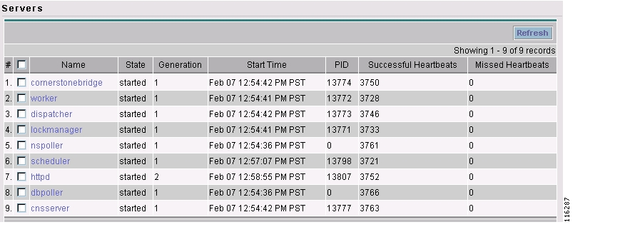
Step 3
The Server Status page appears, as shown in Figure B-1.
Figure B-1 ISC Server Status
Step 4
Symptom 2
The service request is in the Wait Deployed state.
Recommended Action
This concerns the devices that are configured to use the CNS 2100 Series Intelligence Engine as the access method. If the devices are offline and a configlet was generated for it, the service request will move into the Wait Deployed state. As soon as the devices come online, the list of configlets will be downloaded and the status of the device will change.
Symptom 3
The service request is in the Failed Audit state.
Recommended Action
At least one command is missing on the device. Perform the following steps:
Step 1
Step 2
Step 3
Symptom 4
The service request is in the same state as it was before a deployment.
Recommended Action
If after a deployment a service request state remains in its previously nondeployed state (Request, Invalid, or Pending), it's an indication that the provisioning task did not complete successfully. Use the steps described in General Troubleshooting Guidelines to find out the reason for the service request failure.
Symptom 5
You receive the following out-of-memory error: OutOfMemoryError.
Recommended Action
Perform the following steps:
Step 1
The Control Center Hosts page is displayed.
Step 2
The menu buttons for the Hosts page are enabled.
Step 3
The Host Configuration window is displayed.
Step 4
Step 5
Change the Xmx256M attribute to Xmx384M or Xmx512M.
Symptom 6
ISC will not remove a route target import/export for a VPN.
Scenario: When an MPLS service request is edited to be associated to a new VPN, the old VPN will only be removed if it is associated with only one interface. The relationship between the service request and the customer is via the VPN. The optional Customer field in a service request does not have any bearing on configuration. For example, if an MPLS service request for custA exists with vpnB/cercB, but needs to be modified to reflect vpnA/cercA, modifying the service request to use vpnA/cercA will not remove the route target for vpnB from the vrfB if there is more than one interface associated with the same VRF.
Recommended Action
Running the same scenario with only one interface referring to vrfB, ISC will remove vrfB and correctly add vrfA with route target A.
Troubleshooting MPLS VPN and Layer 2 VPN
Go through the troubleshooting steps described in General Troubleshooting Guidelines. If you have failed to troubleshoot or identify the problem, the information in this section provides information on how to gather logs for the development engineer to troubleshoot.
Tip
There is a property in DCPL called Provisioning.Service.mpls.saveDebugData. If this property is set to True, whenever a service request is deployed, a temporary directory is created in ISC_HOME/tmp/mpls.
The directory contains the job ID of the service request prefixed to it, along with a time stamp. This directory contains the uploaded configuration files, service parameters in XML format, and the provisioning and audit results.
The default is set to True.
To verify, perform the following steps:
Step 1
The Control Center Hosts page is displayed.
Step 2
The menu buttons for the Hosts page are enabled.
Step 3
The Host Configuration window is displayed.
Step 4
Step 5
Frequently Asked Questions
Below is a list of FAQs concerning MPLS VPN provisioning. (Question 13 pertains to Layer 2 VPNs.)
Q 1: Why does my service request go to Invalid when I choose provisioning of an extra CE Loopback interface?
It is possible that the auto pick option of the IP addresses was selected for the service request, but a /32 IP address pool was not defined. Check and make sure the IP address and the IP address pool defined for this service request are compatible.
Q 2: When saving a service request, why does it say "CERC not initialized"?
It is necessary to pick a CERC for the link to join. Please check the service request to see if a CERC was selected.
Q 3: Why does creation of a VLAN ID pool require an Access Domain?
VLAN ID pools are associated with an Access Domain. Access Domains model a bridged domain; VLAN IDs should be unique across a Bridged Domain.
PE-POPs must be associated with an Access Domain. An Access Domain can have more than one PE-POP associated with it.
Q 4: In a Paging table, why are the Edit and Delete options disabled, even though only one check box is checked?
This is possible if one or more check boxes are selected in previous windows.
Q 5: Why can I not edit an MPLS VPN or L2VPN policy?
If a service request is associated with a policy, that policy can no longer be edited.
Q 6: I am unable to create a CERC—can you explain why?
You have to define a Route Target pool before you create a CERC, unless you specify the Route Targets manually.
Q 7: How can I modify the configlet download order between the PE, CE, and PE-CLE devices?
There is a property called Provisioning.Services.mpls.DownloadWeights.* that allows you to specify the download order for the following device types: PE, CE, PE-CLE, and MVRF CE.
For example, to ensure that the configlet is downloaded to the PE before it's downloaded to the CE, configure the Provisioning.Services.mpls.DownloadWeights.weightForPE property with a weight value greater than that of the CE.
Q 8: What does this property Provisioning.Service.mpls.reapplyIpAddress do?
If this property is set to True, during deployment of a decommissioned service request, this property will keep the IP address on the CE and PE intact on the router to maintain IPv4 connectivity to the CE.
Q 9:When I create a multi-hop NPC between a CE and PE through at least one PE-CLE device, why do I see some extra NPCs created?
IP Solution Center creates the extra NPCs to prevent operators from having to enter the same information again. A CE can now be connected to the PE-CLE device, and a new NPC will be created that will connect the new CE to a PE over the PE-CLE-to-PE NPC link.
Q 10: During service request provisioning, in the Interface selection list box, why don't I see the entire list of interfaces on the device?
This is probably due to a particular interface type being specified in the service policy. If that is the case, only interfaces of the specified interface type are displayed.
Q 11: Why do BGP and EIGRP not appear in the Routing protocol selection list for a service request associated to a No-CE policy?
BGP and EIGRP require certain CE-related parameters, such as the customer AS number and the CE's IP address. Since none of these parameters are requested in a No-CE policy, it is not feasible to provision these protocols. To provision a service request with BGP or EIGRP, use a policy with the CE present option specified, and you can set the CE to unmanaged.
Q 12: Why do the routing protocols BGP and EIGRP not appear when I choose No CE?
If there is no CE in the scenario, BGP and EIGRP are not supported.
Q 13: This is a Layer 2 VPN question: Why does my service request go to Invalid with the message "loopback address missing"?
This is because the loopback address required to peer the pseudowire between PEs has not been defined in the PE-POP object in ISC.
![]()
![]()
![]()
![]()
![]()
![]()
![]()
![]()
Posted: Mon Feb 18 15:15:06 PST 2008
All contents are Copyright © 1992--2008 Cisco Systems, Inc. All rights reserved.
Important Notices and Privacy Statement.