|
|

Table Of Contents
Spanning Multiple Autonomous Systems
Routing Between Autonomous Systems
Exchanging VPN Routing Information
Routing Between Subautonomous Systems in a Confederation
Using ISC to Span Multiple Autonomous Systems
Using Templates to Support Inter-Autonomous System Solutions
Creating the Inter-AS Templates
Spanning Multiple Autonomous Systems
This chapter describes how to configure spanning multiple autonomous systems using the IP Solution Center (ISC) provisioning process. It contains the following sections:
•
Overview
•
•
•
•
Overview
The inter-autonomous system for MPLS VPNs feature allows an MPLS VPN to span service providers and autonomous systems. An autonomous system is a single network or group of networks that is controlled by a common system administration group and that uses a single, clearly defined routing protocol.
As VPNs grow, their requirements expand. In some cases, VPNs need to reside on different autonomous systems in different geographic areas. Also, some VPNs need to extend across multiple service providers (overlapping VPNs). Regardless of the complexity and location of the VPNs, the connection between autonomous systems must be seamless to the customer.
The inter-autonomous systems for MPLS VPNs feature provides that seamless integration of autonomous systems and service providers. Separate autonomous systems from different service providers can communicate by exchanging IPv4 network layer reachability information (NLRI) in the form of VPN-IPv4 addresses. The autonomous systems' border edge routers use the Exterior Border Gateway Protocol (EBGP) to exchange that information. An interior gateway protocol (IGP) then distributes the network layer information for VPN-IPv4 prefixes throughout each VPN and each autonomous system. Routing information uses the following protocols:
•
•
An MPLS VPN with inter-autonomous system support allows a service provider to provide to customers scalable Layer 3 VPN services, such as web hosting, application hosting, interactive learning, electronic commerce, and telephony service. A VPN service provider supplies a secure, IP-based network that shares resources on one or more physical networks.
The primary function of EBGP is to exchange network reachability information between autonomous systems, including information about the list of autonomous system routes. The autonomous systems use EGBP border edge routers to distribute the routes, which include label switching information. Each border edge router rewrites the next-hop and MPLS labels. See Routing Between Autonomous Systems for more information.
Inter-autonomous system configurations supported in an MPLS VPN can include:
•
•
Benefits
The inter-autonomous system MPLS VPN feature provides the following benefits:
•
The inter-autonomous systems for MPLS VPNs feature allows service providers, running separate autonomous systems, to jointly offer MPLS VPN services to the same end customer. A VPN can begin at one customer site and traverse different VPN service provider backbones before arriving at another site of the same customer. Previously, MPLS VPNs could only traverse a single BGP autonomous system service provider backbone. The inter-autonomous system feature allows multiple autonomous systems to form a continuous (and seamless) network between a service provider's customer sites.
•
The inter-autonomous systems for MPLS VPNs feature allows a service provider to create a VPN in different geographic areas. Having all VPN traffic flow through one point (between the areas) allows for better rate control of network traffic between the areas.
•
The inter-autonomous systems feature can make IBGP meshing in an autonomous system more organized and manageable. You can divide an autonomous system into multiple, separate sub-autonomous systems and then classify them into a single confederation (even though the entire VPN backbone appears as a single autonomous system). This capability allows a service provider to offer MPLS VPNs across the confederation because it supports the exchange of labeled VPN-IPv4 network layer reachability information between the sub-autonomous systems that form the confederation.
Routing Between Autonomous Systems
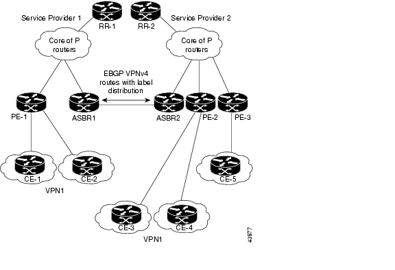
Figure 13-1 illustrates one MPLS VPN consisting of two separate autonomous systems. Each autonomous system operates under different administrative control and runs a different IGP. Service providers exchange routing information through EBGP border edge routers (ASBR1 and ASBR2).
Figure 13-1 EBGP Connection Between Two Autonomous Systems
This configuration uses the following process to transmit information:
1.
2.
3.
•
•
4.
•
•
To propagate the EBGP VPN-IPv4 neighbor host route, use the redistribute connected subnets command. The EBGP VPN-IPv4 neighbor host route is automatically installed in the routing table when the neighbor comes up. This is essential to establish the label-switched path between PE routers in different autonomous systems.
Exchanging VPN Routing Information
Autonomous systems exchange VPN routing information (routes and labels) to establish connections. To control connections between autonomous systems, the PE routers and EBGP border edge routers maintain a Label Forwarding Information Base (LFIB). The LFIB manages the labels and routes that the PE routers and EBGP border edge routers receive during the exchange of VPN information.
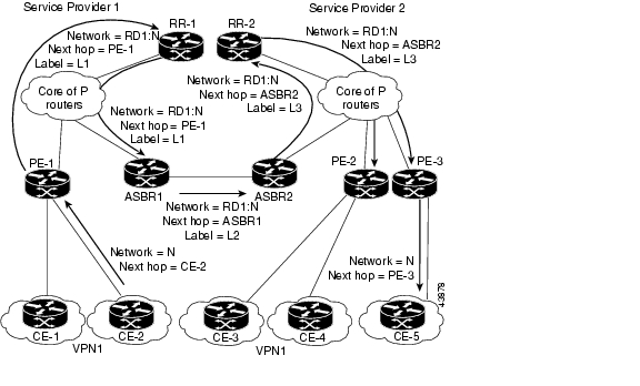
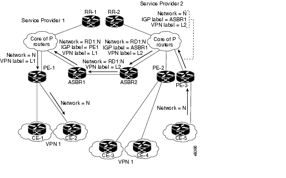
Figure 13-2 illustrates the exchange of VPN route and label information between autonomous systems. The autonomous systems use the following guidelines to exchange VPN routing information:
Routing information includes:
•
•
•
An RD1: route distinguisher is part of a destination network address to make the VPN-IPv4 route globally unique in the VPN service provider environment.
The ASBRs are configured to change the next hop (next-hop-self) when sending VPN-IPv4 NLRIs to the IBGP neighbors. Therefore, the ASBRs must allocate a new label when they forward the NLRI to the IBGP neighbors.
Figure 13-2 Exchanging Routes and Labels Between Two Autonomous Systems
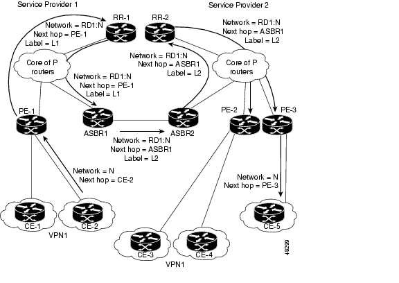
Figure 13-3 illustrates the exchange of VPN route and label information between autonomous systems. The only difference is that ASBR2 is configured with the redistribute connected command, which propagates the host routes to all PEs. The redistribute connected command is necessary because ASBR2 is not the configured to change the next hop address.
Figure 13-3 Host Routes Propagated to All PEs Between Two Autonomous Systems
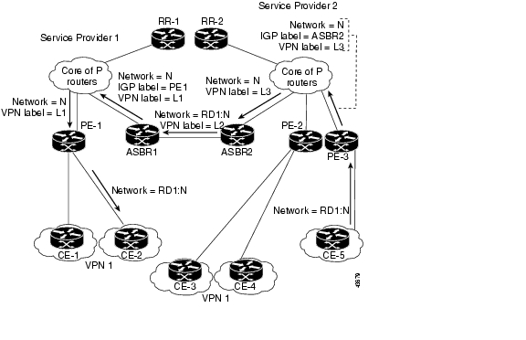
Figure 13-4 illustrates how packets are forwarded between autonomous systems in an interprovider network using the following packet forwarding method:
Packets are forwarded to their destination via MPLS. Packets use the routing information stored in the LFIB of each PE router and EBGP border edge router. The service provider VPN backbone uses dynamic label switching to forward labels.
Each autonomous system uses standard multi-level labeling to forward packets between the edges of the autonomous system routers (for example, from CE-5 to PE-3). Between autonomous systems, only a single level of labeling is used, corresponding to the advertised route.
A data packet carries two levels of labels when traversing the VPN backbone:
•
•
Figure 13-4 Forwarding Packets Between Two Autonomous Systems
Figure 13-5 illustrates shows the same packet forwarding method, except the EBGP router (ASBR1) forwards the packet without reassigning it a new label.
Figure 13-5 Forwarding Packets Without Reassigning a New Label
Routing Between Subautonomous Systems in a Confederation
A VPN can span service providers running in separate autonomous systems or between multiple subautonomous systems that have been grouped together to form a confederation.
A confederation reduces the total number of peer devices in an autonomous system. A confederation divides an autonomous system into subautonomous systems and assigns a confederation identifier to the autonomous systems.
In a confederation, each subautonomous system is fully meshed with other subautonomous systems. The subautonomous systems communicate using an IGP, such as Open Shortest Path First (OSPF) or Intermediate System-to-Intermediate System (IS-IS). Each subautonomous system also has an EBGP connection to the other subautonomous systems. The confederation EBGP (CEBGP) border edge routers forward next-hop-self addresses between the specified subautonomous systems. The next-hop-self address forces the BGP to use a specified address as the next hop rather than letting the protocol choose the next hop.
You can configure a confederation with separate subautonomous systems in two ways:
•
•
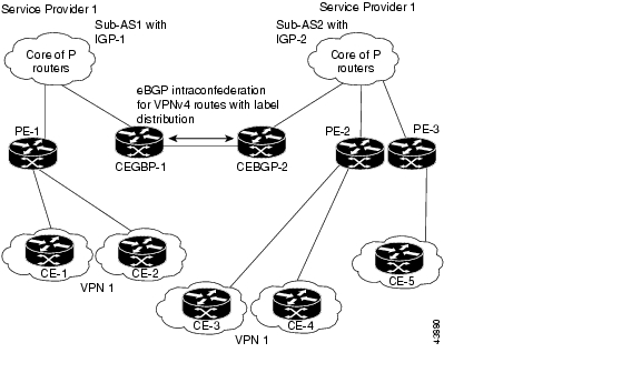
Figure 13-6 illustrates a typical MPLS VPN confederation configuration. In this confederation configuration:
•
•
•
Figure 13-6 EGBP Connection Between Two AS's in a Confederation
In this confederation configuration:
•
•
•
The next-hop-self address is included in the label (as the value of the EBGP next-hop attribute). Within the sub-autonomous systems, the CEBGP border edge router address is distributed throughout the IBGP neighbors and the two CEBGP border edge routers are known to both confederations.
Using ISC to Span Multiple Autonomous Systems
As described in Exchanging VPN Routing Information, autonomous systems exchange VPN routing information (routes and labels) to establish connections. To control connections between autonomous systems, the PE routers and Exterior BGP ASBRs (Autonomous System Boundary Routers) maintain a Label Forwarding Information Base (LFIB). The LFIB manages the labels and routes that the PE routers and EBGP border edge routers receive during the exchange of VPN information.
The ASBRs are configured to change the next hop (next-hop-self) when sending VPN-IPv4 network layer reachability information to their IBGP neighbors. Therefore, the ASBRs must allocate a new label when they forward the NLRI to their IBGP neighbors.
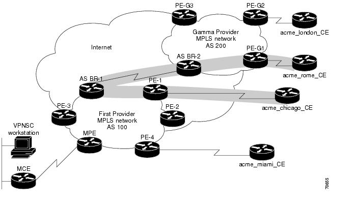
Figure 13-7 shows the example ISC network used in this section.
Figure 13-7 Example VPN Network with Two Autonomous Systems
In order for traffic from Acme_Chicago in AS 100 to reach Acme_Rome in AS 200, ISC must provision two links only:
•
•
As shown in Figure 13-7, ISC routes the VPN traffic from PE-1 to ASBR-1, from ASBR-1 to ASBR-2, then from ASBR-2 to PE-G1; finally the traffic is routed to its destination, Acme-Rome.
ASBR-1 and ASBR-2 must run BGP (Border Gateway Protocol). Then iMP-BGP (interior Multiprotocol BGP) handles the routes between PE-1 to ASBR-1 in AS 100 and the routes between PE-2 to ASBR-2 in AS 200. eMP-BGP (exterior Multiprotocol BGP) handles the routes between ASBR-1 and ASBR-2.
Tip
A VPN-IPv4 address (also referred to as a VPNv4 address) is the combination of the IPv4 address and the 8-byte route distinguisher (RD). Combining the RD and the IPv4 address makes the IPv4 route globally unique across the MPLS VPN network. BGP considers an IPv4 address as different from another IPv4 address that has the same network and subnet mask when the route distinguishers are different.
Using Templates to Support Inter-Autonomous System Solutions
This section covers how ISC supports inter-autonomous system (inter-AS) and inter-provider VPNs through ISC templates.
Note
Inter-AS 10B Hybrid Model
The current release of ISC provides two pairs of template scripts for provisioning and decommissioning inter-AS 10B Hybrid VPNs:
•
•
Using the second pair of template scripts, the provider can create a new pair of data-files for provisioning and decommissioning a new inter-AS VPN on the ASBR, as and when added.The default inter-AS scripts can be modified to create or change scripts for modifying inter-AS configuration.
The following commands are supported in the VPN-independent inter-AS 10B Hybrid default templates:
•
•
•
•
–
–
–
–
–
•
The following commands are supported in the VPN-specific inter-AS 10B Hybrid default templates:
•
•
•
–
–
Inter-AS RT-Rewrite
ISC supports inter-AS RT-rewrite configuration on the ASBR. Velocity Template Language (VTL) template scripts for provisioning and decommissioning of RT-rewrite commands are provided as part of the inter-AS 10B hybrid templates, covered in the next section. You can edit these VTL scripts to create your own templates for the respective use-case.
Creating the Inter-AS Templates
Note
The default inter-AS templates are provided in the Examples templates directory in ISC. The templates are created from the Service Design window, which you access by choosing:
Service Design > Templates > Examples
The templates for Inter-AS 10b hybrid are:
•
•
•
•
You can create and change templates, using the default provisioning and decommissioning scripts, based on the respective use-case. Because the inter-AS configurations are mostly a one time setup, the templates are downloaded from the device console only, but are not attached to a service request.
The ISC templates feature supports a basic deployment check to determine whether the template data file was successfully deployed or whether there was any command that failed to deploy. In addition, you can select the data-type for the variables, which facilitates entering the right values during data-file creation in the user interface.
After you successfully create the template data file that contains the inter-AS CLIs, you can download the template data file onto the ASBR or route reflector using the ISC Device Console window, which you access by choosing:
Service Inventory > Device Console
The templates you created under Service Design can be selected for deployment on a device or a device-group.
Note
![]()
![]()
![]()
![]()
![]()
![]()
![]()
![]()
Posted: Mon Feb 18 15:04:55 PST 2008
All contents are Copyright © 1992--2008 Cisco Systems, Inc. All rights reserved.
Important Notices and Privacy Statement.