|
|

1SUPPLEMENTAL LICENSE AGREEMENT
3Setting Up the Layer 2 Network
4Installing and Configuring the Cisco Ethernet Subscriber Solution Engine 1105
IMPORTANT—READ CAREFULLY: This Supplemental License Agreement ("SLA") contains additional limitations on the license to the Software provided to Customer under the Software License Agreement between Customer and Cisco. Capitalized terms used in this SLA and not otherwise defined herein shall have the meanings assigned to them in the Software License Agreement. To the extent that there is a conflict among any of these terms and conditions applicable to the Software, the terms and conditions in this SLA shall take precedence.
By installing, downloading, accessing or otherwise using the Software, Customer agrees to be bound by the terms of this SLA. If Customer does not agree to the terms of this SLA, Customer may not install, download, or otherwise use the Software.
1. ADDITIONAL LICENSE RESTRICTIONS.
2. DESCRIPTION OF OTHER RIGHTS AND LIMITATIONS.
Please refer to the Cisco Systems, Inc. Software License Agreement.
 |
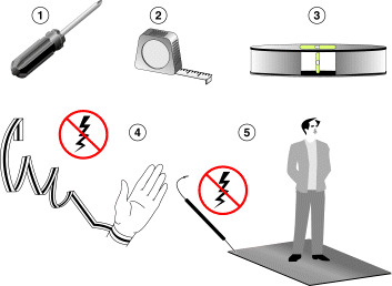
Warning Read the installation instructions before you connect the system to its power source. |
|
Warning Only trained and qualified personnel should be allowed to install, replace, or service this equipment. |
|
Warning This unit is intended for installation in restricted access areas. A restricted access area is where access can only be gained by service personnel through the use of a special tool, lock and key, or other means of security, and is controlled by the authority responsible for the location. |
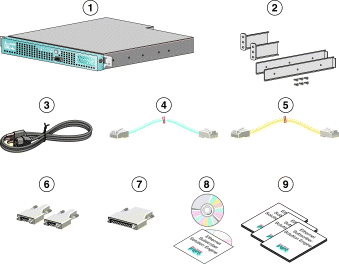
The Cisco Ethernet Subscriber Solution Engine 1105 (Cisco ESSE) package includes the following:
To install the Cisco Ethernet Subscriber Solution Engine 1105, you will need the following:
| 1 | 4 | ||
| 2 | 5 | ||
| 3 |
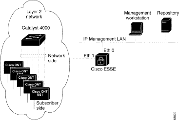
As part of the installation process, you must configure your Solution Engine. During this process, you are prompted to enter information for the two Ethernet interface ports. Ethernet 0 is used for IP communications, and Ethernet 1 is used for L2NMP management packet communications.
The IP interface is used for IP-based web-server-to-web-browser communications and can be physically isolated to a separate LAN, if you wish.
The L2NMP interface is used to exchange management packets with Cisco ONT devices located throughout the layer 2 network.
General notes on network configuration are provided in Table 1. An example of a Layer 2 network showing a Cisco ESSE is shown in Figure 1.
Table 1 Network Configuration Table
| Device Type | Tasks | ||
|---|---|---|---|
|
The Cisco ESSE to Cisco ONT network switching fabric for the L2NMP interface is based on communicating at the Layer 2 level. The network switching fabric may either be configured on a single VLAN or as IEEE 802.1q trunks with appropriate VLANs.
If the network switching fabric is configured as a single VLAN, L2NMP management traffic and Cisco ONT subscriber traffic will share this single VLAN. The Cisco ESSE L2NMP interface, for L2NMP management packet exchange, can potentially become overloaded due to excessive packet processing of the additional end user traffic or other high traffic source or surge (that is, flooding or, potentially, the end user data) causing disruption of L2NMP management packet exchange. When the high traffic recedes, L2NMP packet communication resumes.
To avoid this potential issue, logically separate these two traffic streams by implementing the appropriate IEEE 802.1q trunk and VLAN configurations across your network.
L2NMP packets generated by Cisco ONT devices are without VLAN tags and will be placed onto the native VLAN (as required by IEEE 802.1q). Therefore, if you are distributing Cisco ONTs across multiple VLANS in your network, each Cisco ONT network access port must be defined as a trunk and must contain the appropriate native VLAN and the second non-native VLAN for end user traffic. If you clear all other unnecessary VLANs from this trunk definition, traffic on this trunk will be kept to a minimum.
The network access port on the Cisco ESSE L2NMP interface must, therefore, also be defined as a trunk and must contain all native VLANs from all Cisco ONT network access port trunk definitions. To prevent excess packet processing on the Cisco ESSE L2NMP interface, clear all extraneous VLANs from this trunk.
If all Cisco ONT access ports in the network are in the same native VLAN, the L2NMP interface's access port need only be in this same native VLAN and does not have to be defined as a trunk. To prevent excess packet processing on the Cisco ESSE L2NMP interface, ensure that all the Cisco ONT network access ports and the Cisco ESSE L2NMP interface are the only devices on this native VLAN.
To separate these two traffic streams, verify that the customer premises equipment (CPE) subscriber side port is IEEE 802.1q compliant, defined as a trunk, and has the same native VLAN and end user VLANs defined.
For more information on configuring VLANs and VLAN trunks on the Access Switches, refer to the software configuration guides for the switches.
Install the system in compliance with your local and national electrical codes.
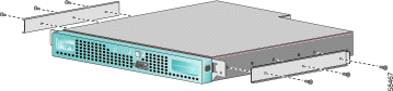
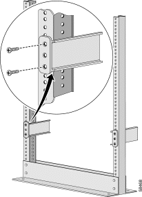
Step 2 Attach the rack-mount brackets to the rack. Make sure that all three bracket holes line up with the holes on the rack.
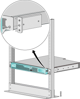
Step 3 Put the chassis into the rack and tighten the screws.
 |
Caution The rack-mount kit is not intended for use as a slide rail system. You must complete installation of the front-mount bracket assembly by securely fastening the chassis into the rack. |
|
Warning This product relies on the building's installation for short-circuit (overcurrent) protection. Ensure that a fuse or circuit breaker no larger than 120 VAC, 15A U.S. (240 VAC, 10A outside the U.S.) is used on the phase conductors (all current-carrying conductors). |
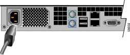
Step 4 Connect the AC power receptacle to the AC power source with the power cable.
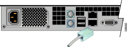
Step 5 Plug the network connection into the Ethernet 0 port (the lower port).
After you install and plug in the Cisco Ethernet Subscriber Solution Engine 1105, you are ready to configure it at a console through the Command Line Interface (CLI).
Step 2 Press the power switch to turn on the Cisco Ethernet Subscriber Solution Engine 1105.
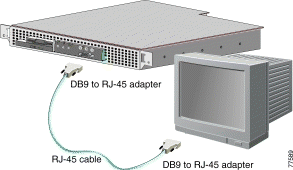
Step 3 Open a window for the system console, using a terminal emulation program if necessary.
The system begins booting and sends messages to the console window. When the system finishes booting, the localhost: login prompt appears. When the login prompt appears, you can configure the system.
Step 4 Enter setup at the login: prompt, then enter responses to the prompts that appear. Table 2, describes how to respond to the prompts.
Press Enter to enter a response and proceed to the next prompt. Press Backspace or Delete to delete characters.
 |
Tip If you enter data incorrectly and need to make corrections, exit the setup program by pressing Ctrl-c, or by entering no after the final prompt. Then perform an erase config and rerun the setup program. |
The login prompt appears. Log in as the user setup to run the setup program.
The setup program exits without saving the configuration, then restarts.
Table 2 Setup Program Description Table
Step 5 Answer the next set of prompts to create a self-signed certificate. This certificate will allow you to access the Cisco Ethernet Subscriber Solution Engine 1105 securely, using HTTPS, until you are able to obtain a certificate from a certificate authority (CA). Table 3 describes how to respond to the prompts. After you finish responding to these prompts, the Cisco Ethernet Subscriber Solution Engine 1105 will reboot.
|
Tip If you enter data incorrectly and need to correct the information in the self-signed certificate, you must exit the program, perform an erase config, and rerun the setup. |
Table 3 Self-Signed Certificate Table
Step 6 After you finish configuring the Cisco Ethernet Subscriber Solution Engine 1105, specify a mail server to send mail to external domains by entering the following command:
where hostname is the hostname of the SMTP server and ip-address is the IP address of the SMTP server. If you do not specify a mail server, email can only be sent only to the local domain. For more information, see the User Guide for the Cisco Ethernet Subscriber Solution Engine. You can access a PDF of the user guide by clicking View PDF in the product online help.
After configuring the Cisco Ethernet Subscriber Solution Engine 1105, verify the configuration. Perform the following steps at the console to confirm that your settings are correct and that the system can communicate with the network. For more information on CLI commands, refer to the Hardware Installation and Configuration Guide for the Cisco Ethernet Subscriber Solution Engine 1105.
 |
Note For security reasons, Telnet is disabled on the Cisco ESSE by default. You can use the telnetenable enable command. |
Step 2 If you are using a DNS server, enter the following command to verify that the Cisco ESSE can obtain DNS services from the network:
where dns-name is the DNS name of a host that is registered in DNS. If the system cannot obtain the IP address of the host from DNS, use the ip name-server command to configure a working DNS server.
Step 3 Enter the following command to verify that the system can communicate with the network:
where ip-address is the IP address of a host that is accessible on the network. A DNS server is a recommended host to ping because it should always be running and accessible.
Step 4 Enter the command show config to verify that the configuration is as you expected.
Step 5 Enter the show clock command to verify that the system time and date are correct in Coordinated Universal Time (UTC).
Step 6 If the time or date is incorrect, set the correct time and date using the clock command.
Step 7 If your network uses Network Time Protocol (NTP), configure the system to use NTP to set the clock.
Step 8 Enter the exit command to log out of the system. You are now finished using the console. The remaining steps take place at the client system.
To configure a Web browser, perform the following steps on the client system:
Step 2 Enable JavaScript.
Step 3 Configure your browser to accept all cookies.
Step 4 Change the default font to sans serif for improved readability.
For information about performing these steps, see the Hardware Installation and Configuration Guide for the Cisco Ethernet Subscriber Solution Engine 1105 or your browser's documentation.
Connect to the system using a Web browser, and perform the following steps to verify HTTP and HTTPS connectivity:
For example, if the system IP address is 209.165.202.128, enter http://209.165.202.128:1741 .
Step 2 To verify HTTPS connectivity, enter the system IP address in a web browser, prefixed by https. No port number is needed.
For example, if the system IP address is 209.165.202.128, enter https://209.165.202.128.
Step 3 Enter the User Name admin and the password you created during setup in the login dialog box, then click Login.
When the Cisco ESSE is first powered on, it will wait for ONTs to contact the Cisco ESSE. After the ONT has contacted Cisco ESSE the Cisco ESSE will start managing that ONT.
|
Note It takes up to 15 minutes to discover the ONTs after the Cisco ESSE powers on. |
See the online help for details about using the monitoring, configuring, and reporting features.
|
Note Although every effort has been made to validate the accuracy of the information in the printed and electronic documentation, you should also review the documentation on Cisco.com for any updates. |
For information about installing, troubleshooting, and using the Cisco ESSE:
| To learn more about... |
See this document | Product Package (Printed Copy) | Product CD (PDF1 in Documentation directory) | Cisco.com (PDF1 and HTML) |
Cisco Doc. CD (PDF1, HTML) |
Online Help (PDF1) |
|---|---|---|---|---|---|---|
Release Notes for the Cisco Ethernet Subscriber Solution Engine |
||||||
Hardware Installation and Configuration Guide for the Cisco Ethernet Subscriber Solution Engine |
||||||
User Guide for the Cisco Ethernet Subscriber Solution Engine |
||||||
Regulatory Compliance and Safety Information for the Cisco Ethernet Subscriber Solution Engine 1105 |
||||||
Programmer Manual for the Cisco Ethernet Subscriber Solution |
||||||
Finding Documentation for the Cisco Ethernet Subscriber Solution Engine 1105 |
| 1Requires Adobe Acrobat 4.0 or later. |
These sections explain how to obtain documentation from Cisco Systems.
You can access the most current Cisco documentation on the World Wide Web at this URL:
Translated documentation is available at this URL:
http://www.cisco.com/public/countries_languages.shtml
Cisco documentation and additional literature are available in a Cisco Documentation CD-ROM package, which is shipped with your product. The Documentation CD-ROM is updated monthly and may be more current than printed documentation. The CD-ROM package is available as a single unit or through an annual subscription.
Cisco documentation is available in these ways:
http://www.cisco.com/cgi-bin/order/order_root.pl
http://www.cisco.com/go/subscription
You can submit comments electronically on Cisco.com. In the Cisco Documentation home page, click the Fax or Email option in the "Leave Feedback" section at the bottom of the page.
You can e-mail your comments to bug-doc@cisco.com.
You can submit your comments by mail by using the response card behind the front cover of your document or by writing to the following address:
Cisco Systems
Attn: Document Resource Connection
170 West Tasman Drive
San Jose, CA 95134-9883
Cisco provides Cisco.com as a starting point for all technical assistance. Customers and partners can obtain online documentation, troubleshooting tips, and sample configurations from online tools by using the Cisco Technical Assistance Center (TAC) Web Site. Cisco.com registered users have complete access to the technical support resources on the Cisco TAC Web Site.
Cisco.com is the foundation of a suite of interactive, networked services that provides immediate, open access to Cisco information, networking solutions, services, programs, and resources at any time, from anywhere in the world.
Cisco.com is a highly integrated Internet application and a powerful, easy-to-use tool that provides a broad range of features and services to help you with these tasks:
If you want to obtain customized information and service, you can self-register on Cisco.com. To access Cisco.com, go to this URL:
The Cisco Technical Assistance Center (TAC) is available to all customers who need technical assistance with a Cisco product, technology, or solution. Two levels of support are available: the Cisco TAC Web Site and the Cisco TAC Escalation Center.
Cisco TAC inquiries are categorized according to the urgency of the issue:
The Cisco TAC resource that you choose is based on the priority of the problem and the conditions of service contracts, when applicable.
You can use the Cisco TAC Web Site to resolve P3 and P4 issues yourself, saving both cost and time. The site provides around-the-clock access to online tools, knowledge bases, and software. To access the Cisco TAC Web Site, go to this URL:
All customers, partners, and resellers who have a valid Cisco service contract have complete access to the technical support resources on the Cisco TAC Web Site. The Cisco TAC Web Site requires a Cisco.com login ID and password. If you have a valid service contract but do not have a login ID or password, go to this URL to register:
http://www.cisco.com/register/
If you are a Cisco.com registered user, and you cannot resolve your technical issues by using the Cisco TAC Web Site, you can open a case online by using the TAC Case Open tool at this URL:
http://www.cisco.com/tac/caseopen
If you have Internet access, we recommend that you open P3 and P4 cases through the Cisco TAC Web Site.
The Cisco TAC Escalation Center addresses priority level 1 or priority level 2 issues. These classifications are assigned when severe network degradation significantly impacts business operations. When you contact the TAC Escalation Center with a P1 or P2 problem, a Cisco TAC engineer automatically opens a case.
To obtain a directory of toll-free Cisco TAC telephone numbers for your country, go to this URL:
http://www.cisco.com/warp/public/687/Directory/DirTAC.shtml
Before calling, please check with your network operations center to determine the level of Cisco support services to which your company is entitled: for example, SMARTnet, SMARTnet Onsite, or Network Supported Accounts (NSA). When you call the center, please have available your service agreement number and your product serial number.
![]()
![]()
![]()
![]()
![]()
![]()
![]()
![]()
Posted: Mon Apr 14 01:07:59 PDT 2003
All contents are Copyright © 1992--2002 Cisco Systems, Inc. All rights reserved.
Important Notices and Privacy Statement.