|
|

The AS5200 Manager is accessed from within CiscoView. For details using the AS5200 Manager, see the online document Cisco AS5200 Manager Guide, and for a detailed description of the hardware, see Cisco AS5200 Universal Access Server Installation Guide.
This appendix provides a description of:
To access the AS5200 from CiscoView, complete the following steps:
Step 1 Go to the CiscoView - Main window.
Step 2 Select File>Open Device.
Step 3 Enter the IP Address of the AS5200 in the Host field.
Step 4 Enter the Read Community string.
Step 5 Enter the Write Community string.
Step 6 Click OK.
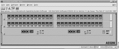
The rear panel of the Cisco AS5200 appears, displaying hardware components, such as ports, modem cards, alarms, and power supply connections.
Step 7 Select logical from the View menu to see an illustration of the logical modem connections. The AS5200 Manager application initializes when you select logical. A box with a large M represents each modem connection.
When you first open an AS5200 device in CiscoView, the rear panel of the device is displayed. Select Configure>logical_card... to display the AS5200 Manager. Figure A-1 shows the Logical view of the AS5200 device.

In the Menu Bar, the main menus are File, View, Configure, Monitor, Options and Help. The following tables describe these menus:
| Item | Explanation |
|---|---|
Displays the back panel of a new device. | |
Reviews a list of devices that you have already displayed without specifying the IP address or other information. | |
Prints the physical view of the device. | |
Exits CiscoView. |
| Item | Explanation |
|---|---|
Refreshes the current display by checking that all information is current. | |
Toggles the size of the device display between 50 and 100 percent. | |
Stack | Appears gray, for use with stackable devices only. |
Displays the rear panel of the device. | |
Displays the logical view, the modem connections on an AS5200. |
The Configure menu varies depending on the device you are using and what you have selected on the device to configure: the device itself, a card or a port.
| Item | Explanation |
|---|---|
line_ds1... | Displays the interface for a DS1 or an E1 line. The DS1 port is a port on a primary rate interface (PRI) card represented by four small colored boxes. |
logical_card... | Displays information about the logical card. |
logical_device... | Displays the Config Logical Device window. From the menu, first select the entire chassis then Configure>logical device... |
modem_port... | Displays the port configuration information for a modem port. Select a port first, then click on Configure>modem port... |
The Monitor menu varies depending on the device you are using and what you have selected on the device to monitor, the device itself, a card or a port.
| Item | Explanation |
|---|---|
line_ds1... | Displays the monitoring information for a DS1 or an E1 line. |
modem_port... | Displays the monitoring information for a selected modem port. |
The Options and Help menus are the same as for CiscoView. For information on these two menus, see the "Using CiscoView" chapter.
The AS5200 Release Note is available on Customer Connection Online or Cisco Customer Documentation, Enterprise C. Table A-5 provides a description of known problems and an explanation of how to correct them:
| Problem | Explanation |
|---|---|
The AS5200 CiscoView DSI Line configuration Dialog Box shows several objects with changeable values. None of the objects in this dialog box are changeable through either CiscoView of SNMP. | Use the router's command line interface to configure these options. |
The alarm data reported in the AS5200 CiscoView DSI Line Alarm Status Dialog Box is not updated when you select a new target port index. | Exit the dialog box, select a new target port, then open the DSI Line Alarm Status dialog box again. |
![]()
![]()
![]()
![]()
![]()
![]()
![]()
![]()
Posted: Wed Sep 25 21:24:38 PDT 2002
All contents are Copyright © 1992--2002 Cisco Systems, Inc. All rights reserved.
Important Notices and Privacy Statement.