|
|

This chapter covers the following information:
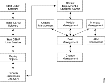
Figure 2-1 outlines the steps involved in installing and using the Cisco 7200/7400 Series Manager software.
The Cisco 7200/7400 Series Manager software is viewed through the Cisco Element Management Framework (CEMF). It is imperative to understand how CEMF works before you can use the Cisco 7200/7400 Series Manager software (for details, refer to the Cisco Element Management Framework User Guide). When you start a CEMF user session, the Cisco 7200/7400 Series Manager software starts as well.
Before you can start a CEMF user session, CEMF must be running. If you receive a message that CEMF is not running, contact your system administrator.
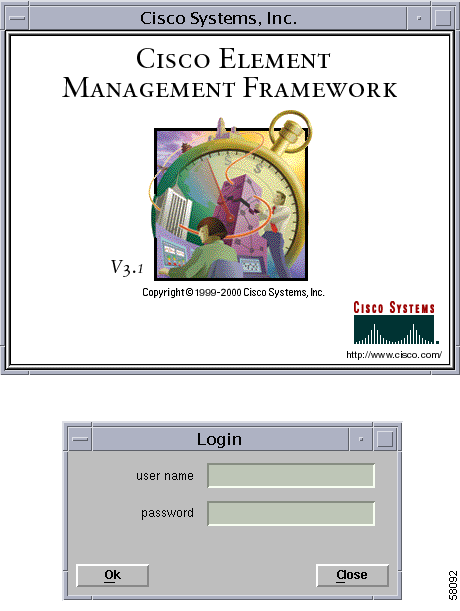
Replace <CEMF_ROOT> with the root directory where CEMF is installed (for example, /opt/CEMF3). The splash screen appears, followed by the Login dialog box (see Figure 2-2).
Step 2 Enter your username and password, then click OK to proceed.
When an invalid username or password is entered, an error message is displayed. Click OK, then enter a valid username and password. If a valid username and password are not entered within three attempts, the login window closes.
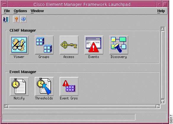
When a valid username and password are entered, the session starts and the CEMF Launchpad window appears as in Figure 2-3.
The CEMF Launchpad window contains two group boxes: CEMF Manager and Event Manager.
The CEMF Manager group box contains the following icons:
The Event Manager group box contains the following icons:
From the File menu, choose Quit.
Step 2 A window appears, asking if you want to quit the session. Click Yes to quit. All active applications are closed and the session terminates.
The first step toward managing a 7200/7400 chassis is to deploy or predeploy the physical objects that you want to manage. Deploying a physical object creates a representative object in CEMF and, as a result, makes the Cisco 7200/7400 Series Manager software aware of the presence of the physical object.
Cisco 7200/7400 Series Manager objects can be discovered automatically or deployed manually. For example, to deploy a chassis, you can either use auto discovery or manually deploy the chassis. If you want to deploy any objects under the chassis, you can either use subchassis discovery or manually deploy each object (interfaces are automatically created when you deploy each port adapter).
If all or most of your chassis objects are physically present and if you have a large number of objects to deploy, you might want to automate these processes by using auto-discovery. For example, if Cisco 7200/7400 Series Manager is installed on an existing network of Cisco 7200/7400 chassis, auto-discovery can dramatically reduce the amount of operator input required. If you want to deploy only a few objects or if many of your objects are not yet physically present, you might want to manually deploy.
The following supporting modules can be deployed using subchassis discovery only; no manual deployment is available for these modules:
You can also deploy either of the following logical objects:
Producing a manageable Cisco 7200/7400 chassis in Cisco 7200/7400 Series Manager is a two-stage process:
1. The first deployment stage is at the chassis level. The Cisco 7200/7400 chassis can be auto-discovered or manually deployed.
2. The second deployment stage is at the subchassis level. This involves either subchassis discovery or deploying subchassis objects (modules) manually.
Cisco 7200/7400 Series Manager objects can be manually predeployed before the physical equipment arrives. The following objects can be predeployed:
For example, if you know that you will be receiving a certain port adapter, you can manually predeploy that port adapter before it is actually present.
Predeployment can save time and effort. When the port adapter becomes available, simply insert it into the chassis, and the Cisco 7200/7400 Series Manager software detects its presence and adopts all the configuration parameters you preapplied to it.
Predeployment can be desirable in a situation in which the expected hardware is known, but configuration information is not readily available. If you want to manually predeploy only, follow only the predeployment procedure in the following "Performing Predeployment" section, then perform device synchronization (for details, see the "Device Synchronization" section). Manually predeployed objects assume whatever configuration is currently on the device, and this information is displayed in the Cisco 7200/7400 Series Manager configuration windows.
The procedure in this section assumes you are expecting the following hardware:
To perform both manual predeployment and offline configuration:
 |
Note You should already have created a site object. If you have not created a site, create one now. For details, refer to the Cisco Element Management Framework User Guide. |
Step 2 Manually deploy the processor.
Step 3 Manually deploy the ATM port adapters. ATM interfaces are deployed simultaneously.
Step 4 Manually deploy the POS port adapters. POS interfaces are deployed simultaneously.
Representative objects are created in Cisco 7200/7400 Series Manager for your expected hardware, modules, and interfaces. All of these objects are in the decommissioned state. For details on manually deploying any of the preceding objects, see the "Deployment and Predeployment" section.
When all of your predeployed objects become available, you can synchronize the Cisco 7200/7400 Series Manager to the device. Synchronization harmonizes the information on the device with the information existent in Cisco 7200/7400 Series Manager (from predeployment).
Synchronization is achieved by commissioning the chassis object. Chassis commissioning allows Cisco 7200/7400 Series Manager to detect the actual presence of the chassis. When you commission the chassis, Cisco 7200/7400 Series Manager discovers not only the presence of the chassis, but the presence of all existing objects within the chassis. (For steps on commissioning a chassis, see the "Commissioning or Decommissioning a Chassis" section).
Synchronization tells Cisco 7200/7400 Series Manager that you now have a real operating system. Working objects are typically placed in a normal state.
Note that device synchronization does not recreate all objects present in the hardware. Some existing objects cannot be recreated, or need to be uploaded manually. You can upload existing ATM connections (for details, see the "Uploading PVCs and ATM QoS Profiles" section).
Auto Discovery is a CEMF application that discovers existing Cisco 7200/7400 chassis, saving the user time and effort. For every Cisco 7200/7400 chassis discovered on the specified network, a shelf object is created with a chassis object beneath it.
The Auto Discovery window can be opened from the Viewer or Discovery icon in the Launchpad. For more information on how to use Auto Discovery, refer to the Cisco Element Management Framework User Guide.
The Auto Discovery application has three mechanisms for discovering chassis:
Auto Discovery can discover chassis on more than one subnetwork using multihop discovery. It can be scheduled to run at preset times (refer to the Cisco Element Management Framework User Guide for details on how to set the schedules). An option is also available to specify the physical location under which discovered objects are created.
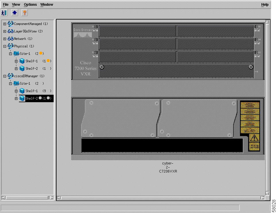
After the Cisco 7200/7400 chassis are detected, an object representing the chassis is created and placed under the site from which auto-discovery was launched. A map of the chassis is also created, as shown in Figure 2-4.
|
Note If you want to auto-discover Cisco7200/7400 chassis that can be managed by the Cisco 7200/7400 Series Manager, the Physical Path option must be enabled and an appropriate physical path terminating in a site must be selected. Next, the Auto Discovery application creates a site containing a shelf with a chassis below the selected physical path for each Cisco 7200/7400 chassis discovered. |
After you deploy a Cisco 7200/7400 chassis, the second step in creating a manageable system is to commission the chassis, which begins the process of subchassis discovery. Subchassis discovery discovers all physical objects within the chassis. Any port adapters and interfaces within the chassis are discovered at this time. Commissioning not only discovers the chassis and all the physical objects within it, but it also initiates heartbeat polling, which allows alarms to be raised on the chassis and all physical objects within it.
Because the chassis is the highest-level object (apart from the "virtual" shelf), when you commission the chassis, all objects under it are commissioned as well. One level below the chassis, if you commission a processor, you commission all physical objects underneath that level. If you commission a port adapter, you commission all interfaces on that port adapter, and so on.
However, note that before you can commission any module within a chassis, the chassis object itself must be commissioned. This means that you must run subchassis discovery by commissioning the chassis before you can commission or decommission any individual objects under it. If you do not want to actively manage all objects within the chassis, you can simply decommission the objects you are not ready to manage.
 |
Tip If you are not ready to commission the chassis, you can manually deploy individual modules within it (for details, see the "Deploying Modules" section). These modules can also be commissioned individually, provided the chassis object is commissioned. |
Once subchassis discovery is performed, all objects are assigned a specific state. For details about potential object states, see the "Object States" section.
Note that during subchassis discovery, modules are auto-named. If you want to rename these objects, you can do so by right-clicking any object, then choosing View > Manipulation > Rename Object. Select the object you want to change in the window that appears, then enter the new name. Click Apply, and the name is changed in Cisco 7200/7400 Series Manager.
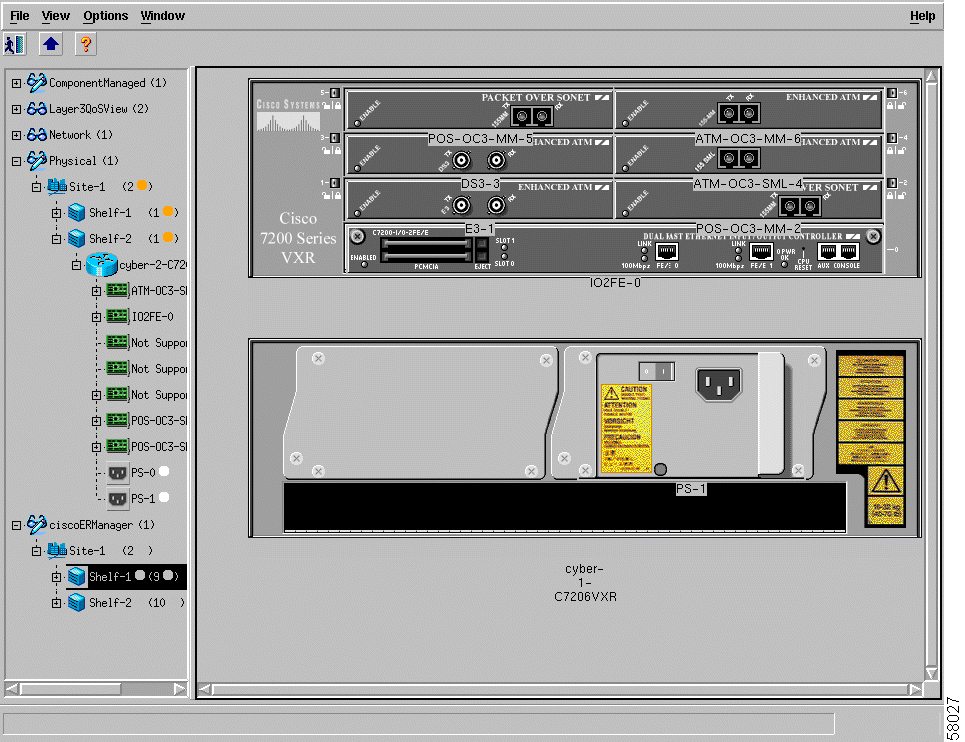
Figure 2-4 shows a Cisco 7206 VXR chassis map in the Cisco 7200/7400 Series Manager view before subchassis discovery. No modules are deployed within the chassis.
|
Note The Cisco 7204 VXR, 7206, and 7401 chassis maps will look different. |
Figure 2-5 shows a Cisco 7206 VXR chassis map in the Cisco 7200/7400 Series Manager view after subchassis discovery. Modules are deployed within the chassis.
When you commission a chassis, subchassis discovery, which discovers and commissions all objects within the chassis, starts automatically. Commissioning means that active management (such as polling) begins on the chassis and all commissioned objects within the chassis.
|
Note After commissioning a chassis, you must manually configure and recommission each newly discovered voice card (see the "Configurin g Voice Cards" section for additional information). Configuring voice cards enables the system to recommission the card. |
Decommissioning a chassis also decommissions all objects within the chassis, which means that active management (such as polling) stops on the chassis and on all objects within the chassis.
For detailed information on commissioning and decommissioning, see the "Chassis Configuration" section.
Using the Cisco 7200/7400 Series Manager to commission a chassis initiates discovery and commissioning activities for all modules and physical interfaces within a selected chassis, with the exception of voice cards. Voice cards are discovered when a chassis initiates commissioning, but are not successfully commissioned. Instead, voice cards are placed in the Card Type Not Set state, and the interfaces in the cards are placed in the Lost Comms state. To successfully commission discovered voice cards and associated interfaces, you must configure each deployed card as T1 or E1 and recommission the card. (Recommissioning is automatically initiated when the card configuration is saved.) To configure and recommission voice cards, use the Voice Card Type Configuration window.
|
Note Once a voice card is configured, you need not reconfigure (and recommission) it if a chassis is decommissioned and later recommissioned. Even though chassis commissioning rediscovers existing modules, the voice card configuration is not cleared, therefore the card commissions properly. |
To configure and recommission voice cards:

Step 2 Select the module from the list shown on the left-hand side of the window.
Step 3 Select the card type button (T1 or E1), then select Save. The card configuration information is saved.
Step 4 Click Commission.
The selected card is recommissioned and the state of the card changes accordingly. The state of the chassis does not change while the voice card is recommissioned. However, you might notice a brief chassis state change, to Information state (in Map Viewer you can see a white border around the chassis), during the process.
|
Tip It is recommended that you ping the Cisco 7200/7400 Series Manager you intend to deploy, to ensure that the device is contactable. However, this is not required, as you can deploy without having connectivity to the device. |
When you deploy a chassis, a shelf is automatically created and placed under the selected site. Multiple shelves and chassis can be deployed under one site, but only one chassis can be deployed under each shelf.
Before you go on, note that you should have already created a site object. For information on creating a site object, refer to the Cisco Element Management Framework User Guide.
To deploy a shelf and a Cisco 7200/7400 chassis:
|
Note You should deploy under the Physical view. You can cancel the operation at any point by clicking Cancel. |
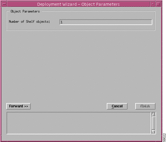
Step 2 Enter the number of shelf objects (or the number of Cisco 7200/7400 chassis) you want to deploy. Click Forward.
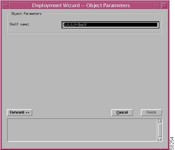
Step 3 Enter the Cisco 7200/7400 Series Manager shelf name, including a prefix and suffix. The prefix "0.0.0.0-Shelf" appears as the default.
You can accept the default prefix or change it. The shelf name must be unique. Click Forward to continue.
|
Note If you did not deploy the chassis from a site object, you might see an additional window that prompts you to choose the exact viewing path you want to place the chassis object under. |
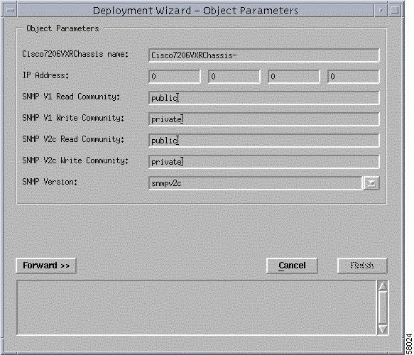
Step 4 Enter the following information:
Step 5 Click Forward to continue.
If you are deploying more than one shelf and chassis at a time, repeat Steps 3 through 5 for any additional shelves and chassis.
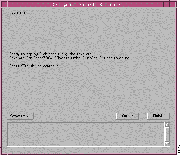
Step 6 The deployment summary details appear in the Deployment Wizard—Summary screen. If the deployment summary information is correct, click Finish. If the information is incorrect, click Cancel to stop deployment. If you click Finish, the shelf and chassis appear under the ComponentManaged, Physical, and Cisco 7200/7400 views.
Step 7 To proceed, you have two options:
This section describes how to manually deploy modules using the Deployment Wizard. You can manually deploy modules before they are physically present (for details, see the "Predeployment" section). In fact, if the modules are not physically present, you need to manually deploy them, because subchassis discovery will not detect their presence. You can also decommission these modules if you do not want them to be actively managed.
Deployable modules include the following:
When you deploy a module, you have two initial deployment options: an auto-named module, or a user-named module.
The user-named option allows you to name the module as you like. For example, if you have a specific naming scheme you want to use, select the user-named option.
The auto-named option assigns an auto-generated name to the module, with the slot number appended to the name. For example, if you deployed an auto-named ATM port adapter in slot 5, the name given would be A-5. This option is most useful when you have numerous port adapters of the same type to deploy.
However, the port adapters must be deployed in sequence within the slots. For example, if you want to deploy ATM port adapters in slots 1 through 5, then the auto-named option is ideal.
Each Cisco 7200/7400 chassis must have a processor deployed.
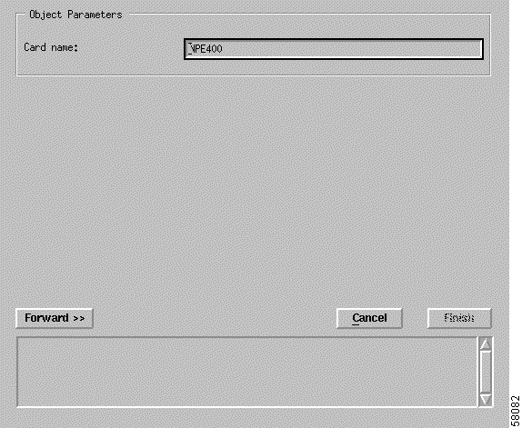
Step 2 Enter a name for the processor; a default name is provided to the user. Then click Forward.
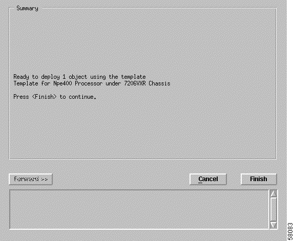
Step 3 The deployment summary details appear in the Deployment Wizard—Summary window. If the deployment summary information is correct, click Finish. If the information is incorrect, click Cancel to stop deployment.
 |
Caution If you deploy a module in a slot that is already occupied, deployment fails at the Finish point. |
The Cisco 7200/7400 chassis supports three types of port adapters: ATM, DS1, POS, and Ethernet. See Table 2-1 for additional details on port adapters and the Cisco 7200/7400 Series Manager menu options.
Table 2-1 displays a list of the port adapters supported by Cisco 7200/7400 Series Manager.
| Product Number | Cisco 7200/7400 Series Manager Menu Option | Card Description |
|---|---|---|
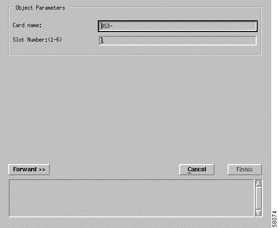
To deploy any type of port adapter:
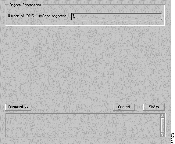
Step 2 Enter the number of port adapter objects you want to deploy.
Step 3 Click Forward.
|
Note The sample windows displayed in this section are for an ATM DS-3 port adapter. |
Step 4 Choose the type of deployment: either auto-named or user-named.
Step 5 Enter the slot number where the card is to be deployed.
Step 6 Click Forward.
|
Caution If you deploy a module in a slot that is already occupied, deployment will fail at the Finish point. |
Step 7 The deployment summary details appear in the Deployment Summary window. If the information is correct, click Finish. Click Cancel if the information is incorrect, and the deployment process stops.
|
Note The number of objects deployed indicates the port adapter object and the number of ports or interfaces on the port adapter. |
The Cisco 7200/7400 chassis support the following modules:
Table 2-2 displays a list of I/O cards and PCMCIA cards supported by Cisco 7200/7400 Series Manager. The deployment for a flash card is not shown, but is similar to the deployment for the I/O cards.
| Card Type | Cisco 7200/7400 Series Manager Menu Option | Card Description |
|---|---|---|
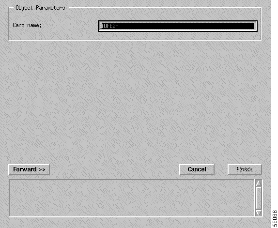
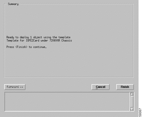
To deploy an I/O card or an SFC:
The Deployment Wizard appears.
Step 2 Click Forward.
Step 3 The deployment summary details appear in the Deployment Wizard—Summary window. If the information is correct, click Finish. If the information is incorrect, click Cancel to stop deployment.
![]()
![]()
![]()
![]()
![]()
![]()
![]()
![]()
Posted: Mon Jan 20 23:30:10 PST 2003
All contents are Copyright © 1992--2002 Cisco Systems, Inc. All rights reserved.
Important Notices and Privacy Statement.