|
|

This chapter describes the Broadband Access Center for Cable (BAC) configuration activities that you perform using these Main Menu options:
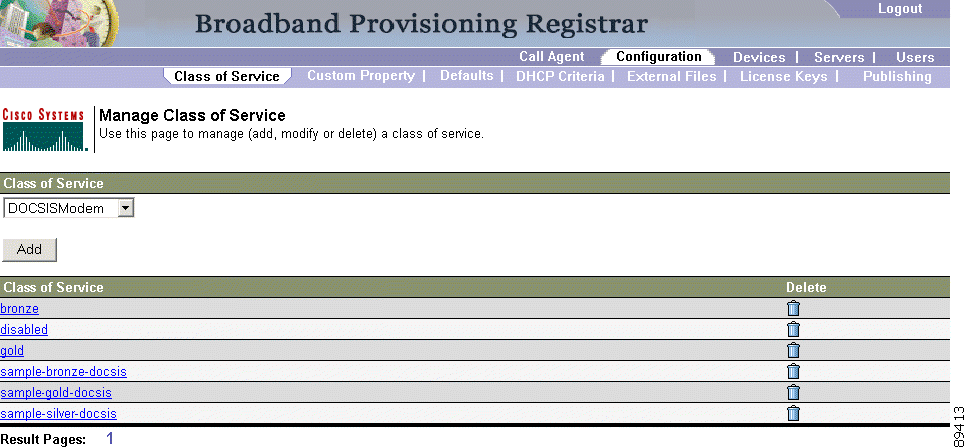
Using the BAC administrator, you can configure the classes of service offered to your customers. For example, you can associate DOCSIS options with different DOCSIS classes of service. You can use the BAC administrator user interface to add, modify, view, or delete any selected class of service. Start with the Manage Class of Service page, as shown in Figure 5-1.
Table 5-1 identifies the fields and buttons shown in Figure 5-1.
Table 5-1 Configure Class of Service Page
|
To add a specific class of service:
Step 2 Choose Class of Service from the Secondary Navigation bar.
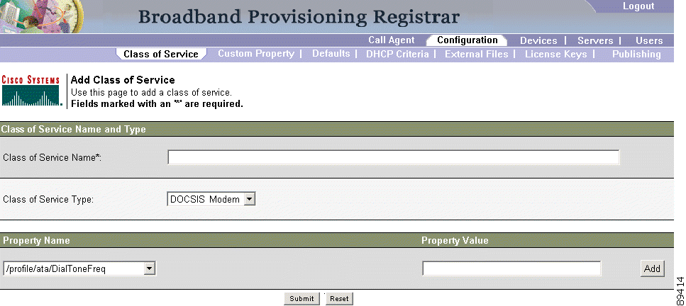
Step 3 Click Add. The Add Class of Service page appears as shown in Figure 5-2. This page identifies the various settings for the selected class of service.
Step 4 Enter the name of your new class of service.
Step 5 Choose a Class of Service Type.
Step 6 Enter a Property Name and Property Value in the appropriate fields.
Assume that you want to create a new class of service called Gold-Classic for DOCSIS modems. You might:
a. Enter Gold-Classic as the Class of Service Name.
b. Choose DOCSIS from the service type drop-down list.
c. Choose the /cos/docsis/file property file name.
d. Enter Gold-Classic.cm in the Property Value field and then continue with the rest of this procedure.
Step 7 Click Add to add the new class of service.
Step 8 Click Submit to finalize the process or Reset to return to the Manage Class of Service page. After adding the class of service, a confirmation page appears to indicate that the addition was performed successfully.
 |
Note Multiple Property Name:Property Value pairs could appear on this page. You use the Delete button to remove any unwanted pairs from the class of service. |
 |
Caution When adding a DOCSIS class of service, you must specify the /cos/docsis/file property with the value being the name of a previously added external file. This file is used when provisioning a DOCSIS device that has this class of service. When adding a PacketCable class of service, you must specify the /cos/packetCableMTA/file property with the value being the name of a previously added external file. This file will be used when provisioning a Packetcable device that has this class of service. |
Table 5-2 identifies the fields and buttons shown in Figure 5-2.
Table 5-2 Add Class of Service Page
|
Note Subsequent device configurations will include the changes you implement here. All existing configurations are regenerated, although the devices on the network will not get the new configuration until they reboot. |
To modify class of service properties:
|
Note Subsequent device configurations will include the changes you implement here. All existing configurations are regenerated, although the devices on the network will not get the new configuration until they reboot. |
Step 2 Choose Class of Service from the Secondary Navigation bar.
Step 3 Choose the class of service to be modified.
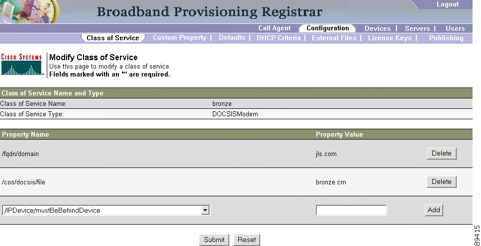
Step 4 Click the link corresponding to the desired class of service. The Modify Class of Service page appears as shown in Figure 5-3. Note that the selected class of service name and type are displayed beneath the page description.
Step 5 Make the necessary modifications to the Property Name Property Value pairs, then click Add.
Step 6 Click Submit to make the modifications to the class of service.
Step 7 After modifying the class of service, a confirmation page appears to indicate that the modification was performed successfully.
Table 5-3 identifies the fields and buttons shown in Figure 5-3.
Table 5-3 Modify Class of Service Page
|
|
Note Multiple Property Name:Property Value pairs may appear on this page. You can use the Delete button to remove any unwanted pairs from the class of service. |
Step 2 Choose Class of Service from the Secondary Navigation bar.
Step 3 Click the Delete icon ( ) for any desired class of service, and a confirmation dialog box appears.
Step 4 Click OK to delete the file or Cancel to return to the Modify Class of Service page. (See Figure 5-3.)
|
Note A class of service cannot be deleted if devices are associated with it or, if it is designated as the default class of service. |
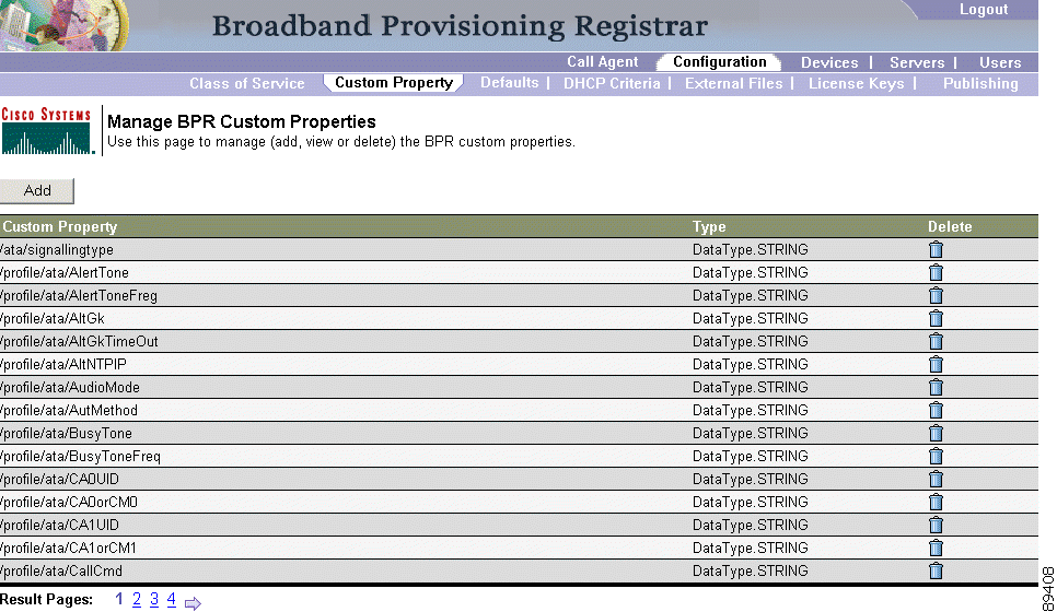
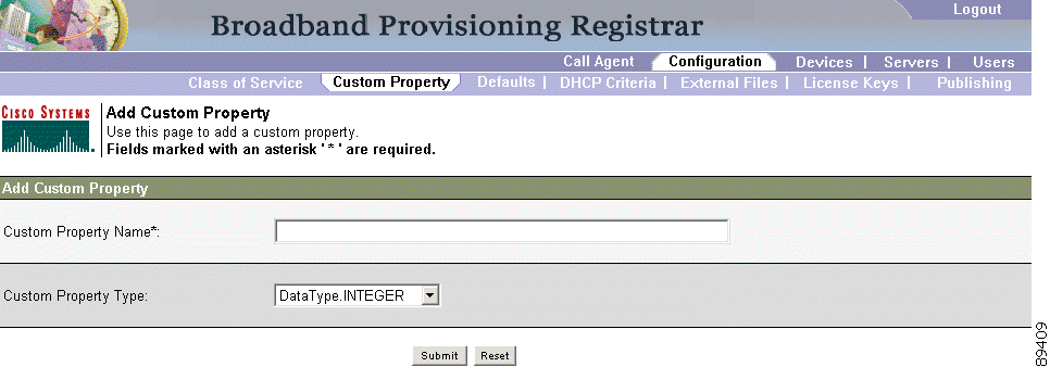
Custom properties let you specify additional information on objects that are stored in the BAC database. To access the Custom Property configuration page:
Step 2 Choose Custom Property from the Secondary Navigation bar and the Configure Custom Properties page appears. (See Figure 5-4.)
Step 2 Enter the name of the new custom property.
Step 3 Choose a custom property type from the drop-down list.
Step 4 Click Submit when complete. Once the property has been added to the administrative database, the Custom property successfully added page appears.
Step 5 Click the link indicated in this page and the Configure Custom Properties page appears. (See Figure 5-4.)
To delete a custom property definitions:
Step 2 Click the Delete icon () corresponding to the desired custom property, and the custom properties deletion dialog box appears.
Step 3 Click OK to delete the custom property. Once the custom property is deleted the Configure Custom Properties page appears.
|
Caution You can delete custom properties even if they are currently in use. This could cause extreme difficulty to other areas where the properties are in use. |
The Defaults page, found under the Configuration option, lets you access the default settings for the overall system, including the regional distribution unit (RDU), Network Registration extensions, and all supported technologies. This section describes how to view and change these default settings:
|
Note BAC is equipped with an automated FQDN generator that is enabled by several of the default configurations. It is important to understand how and why, this takes place. See the "Automatic FQDN Generation" section on page 5-32 for a description of this feature and an example of how to use it. |
The procedure for configuring a specific default type is identical. Complete this procedure to access the desired defaults page and then refer to the appropriate section within this chapter for a description of the various page components.
Step 2 Choose Defaults from the Secondary Navigation bar and the Configure Defaults page appears.
Step 3 Choose the desired default type from the list to the left of the screen. Clicking any of these option links causes the appropriate defaults page to appear.
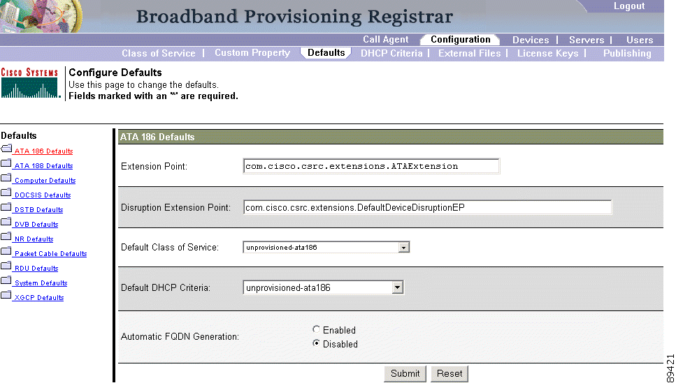
The Cisco ATA 186 is a handset-to-Ethernet adaptor that turns a traditional telephone into an Ethernet IP telephone. Using this device lets you take advantage of the many IP telephony applications by simply connecting an existing analog telephone to it.
The Configure ATA 186 Defaults page (Figure 5-6) displays a list of default values currently available to support the ATA 186.
Table 5-4 identifies the fields and buttons shown in Figure 5-6. In many cases, the parameters that appear in this page also appear in other default pages.
Table 5-4 Configure ATA 186 Defaults Page
|
The Cisco ATA 188 interfaces regular telephones with IP-based ethernet telephony networks. The ATA 188 provides true, next-generation voice-over-IP (VoIP) terminations to support the needs of the enterprise, small-office environments, and emerging VoIP managed voice services and local services market.
The Configure ATA 188 Defaults page displays a list of default values currently available to support the ATA 188. The default parameters displayed for the ATA 188 is identical to that displayed for the ATA 186 although the values you select could be different.
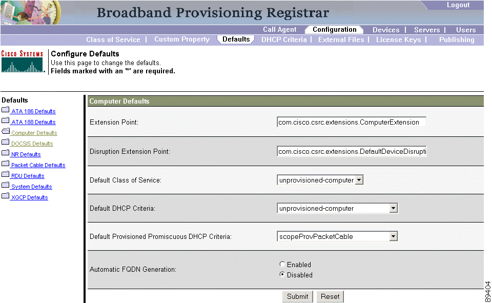
The Computer Defaults page (Figure 5-7) displays a list of default values currently applied to the computers supported by BAC.
Refer to Table 5-4 for the description of all fields and buttons appearing in Figure 5-7. Table 5-5 identifies the fields and buttons that are unique to this defaults page.
Table 5-5 Configure Computer Defaults Page
|
|
Note Any changes made to this page will not affect the current devices. |
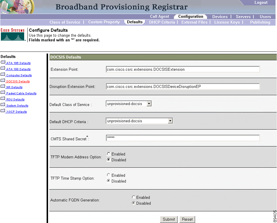
When the DOCSIS Defaults option is selected, the DOCSIS Defaults page appears. This page (Figure 5-8) displays a list of default DOCSIS values currently applied to cable modems supported by BAC.
Refer to Table 5-4 for the description of all fields and buttons appearing in Figure 5-8. Table 5-6 identifies the fields and buttons that are unique to this defaults page.
|
Note Any changes made will not affect the current devices. |
Table 5-6 Configure DOCSIS Defaults Page
|
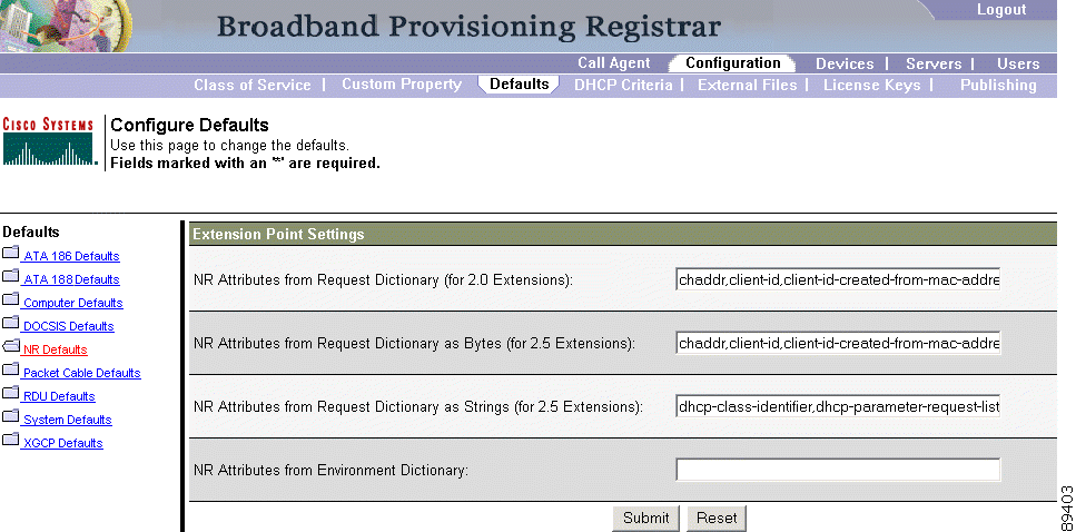
BAC provides Network Registrar (NR) extension points that let BAC pull information from an incoming DHCP request to detect a device's technology. They also let BAC respond to device DHCP requests with options that correspond to the configuration stored at the DPE.
When the NR Defaults option is selected, the NR Defaults page (see Figure 5-9) appears.
Refer to Table 5-4 for the description of all fields and buttons appearing in Figure 5-9. Table 5-7 identifies the fields and buttons that are unique to this defaults page.
Table 5-7 Configure Network Registrar Defaults Page
|
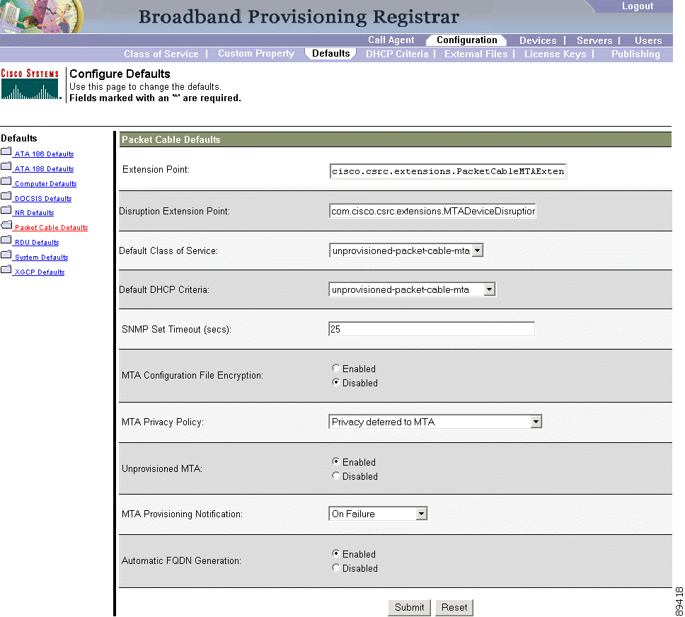
The PacketCable Defaults page identifies those defaults necessary to support the PacketCable voice technology. When selected the PacketCable Defaults page (see Figure 5-10) appears.
Refer to Table 5-4 for the description of all fields and buttons appearing in Figure 5-10. Table 5-8 identifies the fields and buttons that are unique to this defaults page.
Table 5-8 Configure PacketCable (Voice Technology) Defaults Page
|
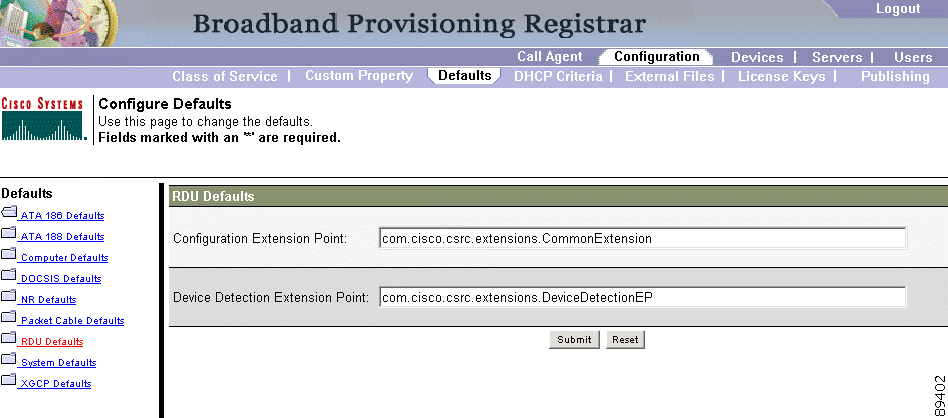
When you select the RDU defaults link, the RDU Defaults page (see Figure 5-11) appears. You use this page to configure RDU extension points to match those in Network Registrar.
Refer to Table 5-4 for the description of all fields and buttons appearing in Figure 5-11. Table 5-9 identifies the fields and buttons that are unique to this defaults page.
Table 5-9 Configure Network Registrar Defaults Page
|
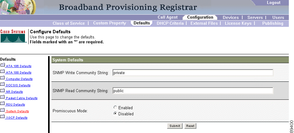
When you select the Systems Defaults link, the System Defaults page (see Figure 5-12) appears.
Refer to Table 5-4 for the description of all fields and buttons appearing in Figure 5-12. Table 5-10 identifies the fields and buttons that are unique to this defaults page.
Table 5-10 Configure Network Registrar Defaults Page
|
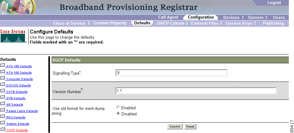
XGCP is a gateway control protocol that lets external call agents control gateways in a Voice over IP (VoIP) environment. The Configure XGCP Defaults page (Figure 5-13) displays a list of default values currently applied to the computers supported by BAC.
Refer to Table 5-4 for the description of all fields and buttons appearing in Figure 5-13. Table 5-11 identifies the fields and buttons that are unique to this defaults page.
Table 5-11 Configure XGCP Defaults Page
|
|
Note Subsequent device configurations will include the changes you implement here. However, all existing configurations do not get changed. To make the changes in any existing configuration, you must regenerate the configuration using the application programming interface (API). |
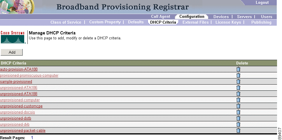
In BAC, DHCP criteria describes the specific criteria for a device when selecting a scope in Network Registrar. For example, a DHCP criteria called provisioned-docsis has an inclusion selection tag called tagProvisioned. The DHCP criteria is associated with a DOCSIS modem. When this modem requests an IP address from the Network Registrar, Network Registrar looks for scopes associated with the scope selection tag tagProvisioned.
To access the DHCP Criteria page:
Step 2 Choose DHCP Criteria from the Secondary Navigation bar and the Manage DHCP Criteria page appears. (See Figure 5-14.)
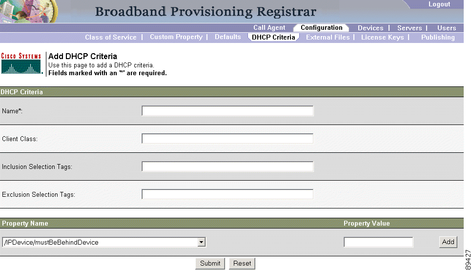
Step 2 Enter the name of the DHCP criteria you want to create.
Step 3 Enter the DHCP Criteria client-class name.
Step 4 Enter the inclusion and exclusion selection tags.
|
Note When creating new DHCP criteria, the client-class and selection tag names you enter must be the exact names from within Network Registrar. Refer to the Network Registrar User's Guide and the Network Registrar CLI Reference if you require additional information about client-class and selection tags. |
Step 5 You can add or modify the properties that are added on the DHCP criteria. Enter or select a Property Name, or select an existing name, and enter or modify the appropriate Property Value.
Step 6 Click Add after changing or creating the property name-property value pair.
Step 7 Click Submit. The DHCP criteria successfully added page appears.
Step 8 On the DHCP criteria page, click the link indicated to return to the Manage DHCP Criteria page. (See Figure 5-14.)
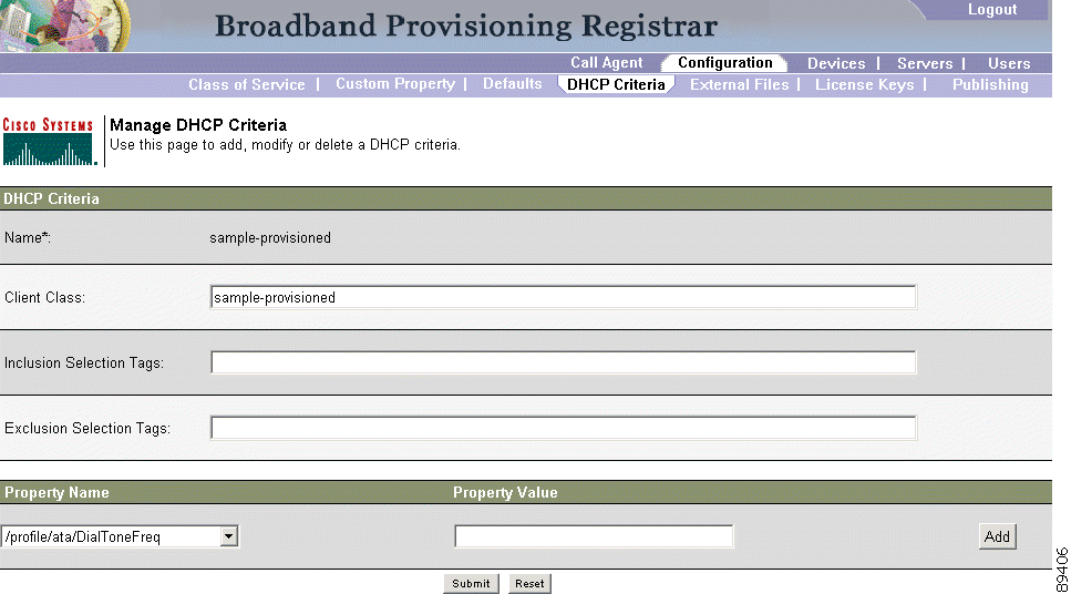
To modify existing DHCP criteria:
Step 2 Make the desired changes, to the client-class, inclusion and exclusion selection tags, and the property value settings.
Step 3 Click Submit. The DHCP criteria successfully modified page appears.
Step 4 On the DHCP criteria page, click the link indicated to return to the Manage DHCP Criteria page. (See Figure 5-14.)
|
Note Subsequent device configurations will include the changes you implement here. All existing configurations are regenerated, although the devices on the network will not get the new configuration until they are rebooted. |
Deleting DHCP criteria using the administrator application will not delete the actual DHCP server configurations from the DHCP server. You must delete the DHCP server configurations manually. To delete an existing criteria:
Step 2 Choose DHCP Criteria from the Secondary Navigation bar and the Manage DHCP Criteria page appears. (See Figure 5-14.)
Step 3 Click the Delete icon () corresponding to the criteria you want to delete, and a deletion dialog box appears.
Step 4 Click OK to delete the criteria or click Cancel to abort the operation. The Manage DHCP Criteria page appears. (See Figure 5-14.)
|
Note You can only delete a DHCP criteria if there are no devices associated with that criteria, and it is not designated as the default DHCP criteria. Should a DHCP criteria have devices associated, you must associate a different DHCP criteria before deleting the criteria. |
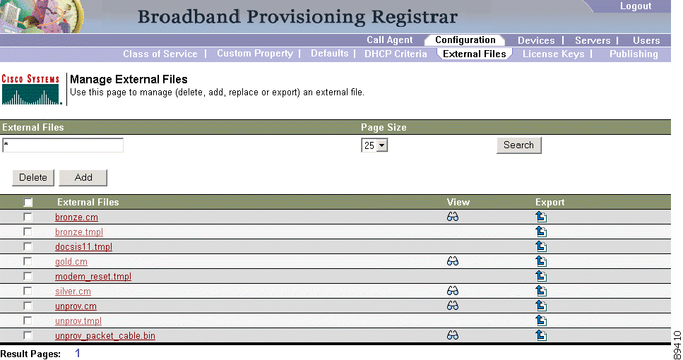
Using the BAC administrative user interface, you can manage the TFTP server files or template files for dynamic generation for DOCSIS and PacketCable MTAs (see Figure 5-17). You can add, delete, replace, or export any file type, including these:
|
Note Template files can be created in any text editor, but must have a tmpl file extension. Refer to the "Developing Template Files" section for additional template information. |
Table 5-12 identifies the fields and buttons shown in Figure 5-17.
Table 5-12 Manage External Files Page
|
To add an existing external file:
Step 2 Choose External Files from the Secondary Navigation bar. The Manage External Files page appears.
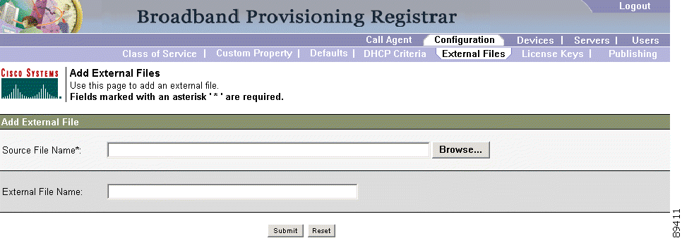
Step 3 Click Add and the Add External Files page appears as shown in Figure 5-18.
Step 4 Enter the Source filename and the external filename.
|
Note If you do not know the exact name source file, use the Browse function to navigate to the desired directory and select the file. By default, file sizes up to 12 MB are supported. |
Step 5 Click Submit. A confirmation page appears to indicate that the file has been added.
Table 5-13 identifies the fields and buttons shown in Figure 5-18.
Table 5-13 Add External Files Page
|
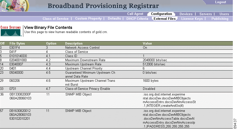
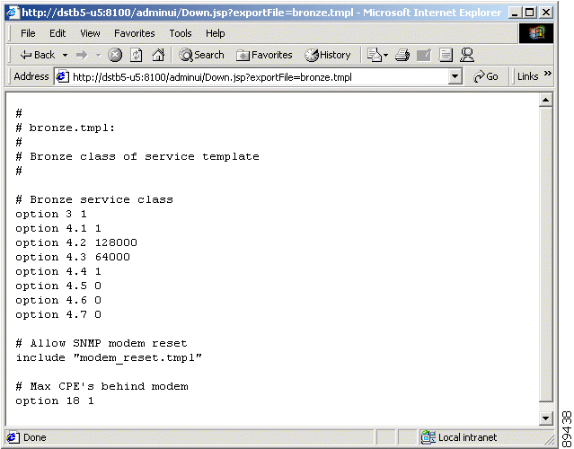
To view the contents of a DOCSIS or PacketCable voice technology external file:
Step 2 Choose External Files from the Secondary Navigation bar. The Manage External Files page appears.
Step 3 Click the Details icon ( ) corresponding to the DOCSIS or PacketCable MTA binary configuration file and a View Binary File Contents page, similar to the one shown in Figure 5-19, appears.
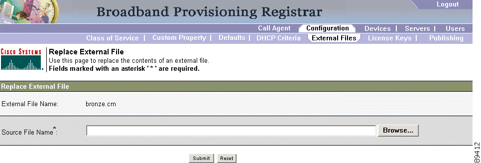
To replace an existing external file:
Step 2 Choose External Files from the Secondary Navigation bar.
Step 3 Click the link that corresponds to the file you want to replace. The Replace External Files page (Figure 5-20) appears. Note that the selected filename already appears on this page.
Step 4 Enter the path and filename of the source file to be used as a replacement for the displayed external filename.
|
Note If you do not know the exact name or location of the source file, use the Browse function to navigate to the desired directory and select the file. |
Step 5 Click Submit. After submitting the replacement file, a confirmation page appears to indicate that the replacement was performed successfully.
|
Note All devices using this file through a class of service are regenerated once the replacement is finished. |
Table 5-14 identifies the fields and buttons shown in Figure 5-20.
Table 5-14 Replace External Files Page
|
You can copy an external files to your local hard drive using the export function. Doing so while using the Internet Explorer browser is somewhat different from using a Netscape browser. This procedure assumes that you are using Internet Explorer and differences that occur with Netscape are identified.
Step 2 Choose External Files from the Secondary Navigation bar.
Step 3 Identify the external file that you want to export.
Step 4 Click the Export icon ( ) and you are prompted to either open the file or save it. Figure 5-21 shows the content of a sample external file.
Step 5 Return to the BAC user interface.
Complete this procedure to delete an existing external file:
Step 2 Choose External Files from the Secondary Navigation bar.
Step 3 In the External Files field, enter the filename of the external file that you want to modify.
Step 4 Click Search. The appropriate file will appear in the External Files list.
Step 5 Choose the appropriate file or files.
Step 6 Click Delete and a confirmation dialog box appears.
|
Caution Deleting a template file that is not directly linked to a class of service, but is referenced by another template file that is linked to a class of service, will cause the configuration regeneration service to fail. |
Step 7 Click OK to delete the file, or click Cancel to return to the Manage External Files page.
|
Note You cannot delete a file as long as it has a class of service associated with it. You must remove the class of service association before proceeding. See the "Configuring the Class of Service" section on page 5-1 for additional information. |
Software licenses are used to activate specific features or to increase the functionality of your installation. Each is available as either a permanent license or an evaluation license.
|
Caution Do not attempt to deploy into a fully operational network with an evaluation license key installed. Any provisioning done using an evaluation license will be disabled when that evaluation license expires. |
You enter software license keys during installation, as described in the Broadband Access Center Installation Guide. However, when you upgrade from an evaluation license to a permanent license, you do not have to re-install the software. You can perform the upgrade directly from the BAC administrator user interface; you do not have to repeat the entire installation process.
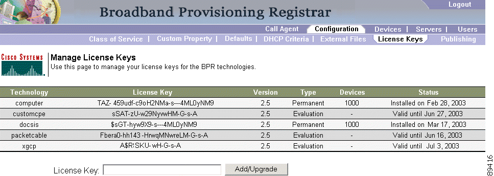
The Manage License Keys page (Figure 5-22) displays a list of licenses that have been entered for your implementation. This BAC release supports both evaluation and permanent licenses for high-speed data (DOCSIS cable modems), PacketCable MTAs, ATAs, and computers. The status of each available license is also displayed as either active, expired, not installed, or identifies the expiration date.
|
Note You can upgrade your evaluation licenses to permanent status. You can also upgrade a permanent license to increase the number of authorized devices. When you reach the limit of you number of licensed devices. You cannot provision new devices, but exiting devices that are already provisioned continue to receive service. |
Table 5-15 identifies the fields and buttons shown in Figure 5-22.
Table 5-15 Manage License Keys Page
|
To add, modify, or delete a license:
Step 2 Choose Licenses from the Secondary Navigation bar.
Step 3 Obtain your new license key from either your Cisco Systems, Inc. representative or the Cisco Technical Assistance Center (TAC) website. See the Preface in this guide for TAC contact information.
Step 4 Enter the new license key in the License Key field.
Step 5 Click Add/Upgrade to install the new license key. If you enter a permanent license key, it overwrites the corresponding evaluation key (if that key was installed). If you enter a license key (permanent or evaluation) for a new technology, it will appear in the technology list.
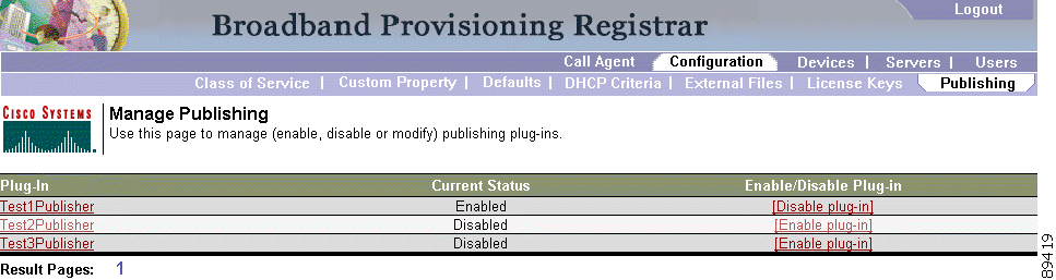
BAC has the capability to publish the provisioning data it tracks to an external datastore in real time. (See Figure 5-23.) To do this, a publishing plug-in must be developed to write the data to the desired datastore.
|
Note BAC does not ship with any publishing plug-ins. You must create your own plug-ins and then manage them from this page. The plug-ins shown in Figure 5-23 are for illustration purposes only. |
|
Note Care must be taken when using publishing plug-ins as they can decrease system performance. |
Table 5-16 identifies the fields and buttons shown in Figure 5-23.
To publish changes to an external datastore:
Step 2 Choose Publishing from the Secondary Navigation bar. The Manage Publishing page appears as shown in Figure 5-23. This page displays a list of all available database plug-ins and identifies the current status of each.
Step 3 Click on the appropriate status indicator to enable or disable the required plug-in. Note that as you click the status, it toggles from enabled to disabled. (See Figure 5-23.)
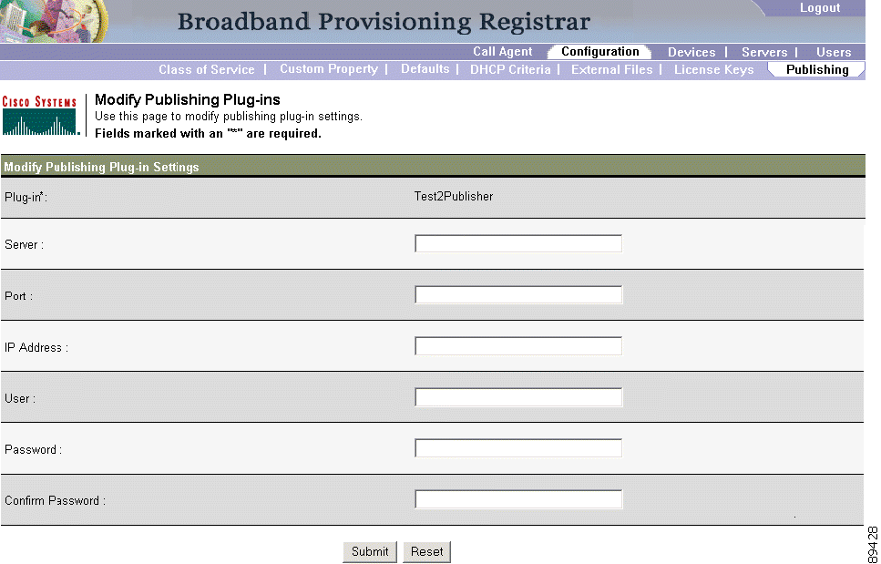
These settings are a convenient way for plug-in writers to store plug-in settings in the RDU for their respective datastore. To modify the publishing plug-in settings:
Step 2 Choose Publishing from the Secondary Navigation bar. The Manage Publishing page appears similar to that shown in Figure 5-24.
Step 3 Click the link corresponding to the plug-in you want to modify. The Modify Publishing Plug-ins page appears similar to that shown in Figure 5-24.
Table 5-17 identifies the fields shown in Figure 5-24.
Table 5-17 Modifying Publishing Plug-ins Page
|
Step 4 Enter the required values in the Server, Port, IP Address, User, Password, and Confirm Password fields. These are all required fields and you must supply this information before proceeding.
Step 5 Click Submit to make the changes to the selected plug-in, or click Reset to clear all fields on this page.
You must configure the Network Registrar DNS server to operate with the KDC. Refer to your Network Registrar documentation, and these instructions, to perform this configuration.
|
Note This example assumes the Kerberos realm is ACME.COM and the KDC is running on the kdc.acme.com host which has DNS record already configured. |
Step 2 Enter this command to create a zone for the Kerberos realm.
Step 3 Enter this command to add the SRV record to the new zone.
Step 4 Enter these commands to save and reload the DNS server.
The SNMP configuration on both the RDU and DPE must permit successful communication between the RDU and an embedded multimedia terminal adapter (E-MTA).
The DPE uses the key material, that you create, during provisioning to create a new user in the E-MTA's SNMPV3 user table. You use the key material to generate the authentication and privacy keys required to access PacketCable MTAs. The RDU, when called by one of three application programming interface (API) calls, creates a local SNMPV3 user. The authentication and privacy keys are created using the same key material and, if the key material is not identical, different keys will be created thereby preventing the RDU from successfully communicating with the E-MTA.
Creating the key material is a two step process. You must run a script command on the RDU and then run a CLI command on the DPE.
|
Note This shared secret is not the same shared secret as the CMTS or the BAC shared secrets. |
Where the <password> is any password, 6 to 20 characters in length, that you create. This password is then used to generate a 46 byte key. This key is stored in a file, called keymaterial.txt, that is located in the <BRP_HOME>/rdu/conf directory.
Step 2 Run the packetcable snmp key-material DPE CLI command, with the <password> used in step 1 to generate that key.
This generates the same 46 byte key on the DPE and ensures that the RDU and DPE(s) are in sync and can communicate securely.
When configuring PacketCable, a fully qualified domain name (FQDN) must reside in the BAC database whenever the KDC queries the registration server for that FQDN. The BAC automatic FQDN generation feature is not limited to use by any single voice technology, but can be used by any other BAC technologies.
An automatically generated FQDN in BAC follows this format:
|
Note In the example FQDN used here, prefix1,6,aa-bb-cc-dd-ee-ffsuffix is the generated host name and domain is the domain name. |
The entry of a prefix and suffix property is optional. If you do not specify these properties, and a host name is not specified during PacketCable MTA provisioning and, if neither the prefix or suffix property is defined in the BAC property hierarchy, the device's MAC address followed by the domain name are used as the generated FQDN.
A device with the MAC address 1,6,aa:bb:cc:dd:ee:ff will have this FQDN generated:
Specifically, when configuring for PacketCable and many other technologies, the domain name property must also be configured. If you do not specify a domain name while provisioning a PacketCable MTA, the BAC property hierarchy is searched and, if it is not found, the MTA is not provisioned. However, if you do specify the domain name during MTA provisioning, that domain name will be used regardless of what domain name property is specified in the BAC property hierarchy.
Properties can be defined at any acceptable point in the of the BAC property hierarchy. You can use the System Defaults, Technology Defaults, DHCP Criteria, or Class of Service to accomplish this, you can also do this at the device level.
There are a few things to consider when entering the information that is used to generate an FQDN. These include:
|
Note The FQDN supports host and domain names as per RFC1035. |
This section provides an example of creating an automatically generated FQDN.
|
Note If a domain is not specified, devices in the class of service will not receive a DHCP configuration from BAC. |
Step 2 Click Submit.
In this example, a device with MAC addr 1,6,00:00:00:00:00:00 will yield an automatically generated FQDN of cisco1-6-aa-bb-cc-dd-ee-fftemp.pctest.com.
![]()
![]()
![]()
![]()
![]()
![]()
![]()
![]()
Posted: Tue Nov 25 06:49:21 PST 2003
All contents are Copyright © 1992--2003 Cisco Systems, Inc. All rights reserved.
Important Notices and Privacy Statement.