|
|

Table Of Contents
1.1 Cisco TransportPlanner Features
1.2.1 Network Design Constraints
1.2.4 Protection Scheme Support
1.3 Cisco TransportPlanner Process Flow
1.4 Planning Traffic in Cisco TransportPlanner
1.5 Cisco TransportPlanner Traffic in the Project Explorer Pane
1.5.1 Point-to-Point Traffic Demands
1.5.4 Aggregated Ethernet Demand
1.6 Auto, Forced, and Locked Parameters
Overview
Note
Cisco MetroPlanner has been renamed as Cisco TransportPlanner starting with release 8.5.
Cisco TransportPlanner Software R8.5 provides a way to model and test wavelength division multiplexing (WDM) optical networks in a graphical environment. The primary purpose of Cisco TransportPlanner is to help sales engineers (SEs) design and validate networks of Cisco Optical Networking System (ONS) 15454 Multi-Service Transport Platforms (MSTP). Using Cisco TransportPlanner Software R8.5, an SE can create multiple instances of a network to modify different parameters in each instance for comparison. Cisco TransportPlanner generates a shelf view of all the sites deployed in the optical network and provides a complete bill of materials (BOM) for the network and the differences between instances of a network.
This chapter describes how you use Cisco TransportPlanner to design, analyze, and optimize new or existing Cisco optical networks and contains the following sections:
•
•
•
•
•
1.1 Cisco TransportPlanner Features
Cisco TransportPlanner Software R8.5 provides a simple tool set for designing optical networks with Cisco ONS 15454 MSTP products. You can enter all of the network parameters or minimal information, such as site distance, and Cisco TransportPlanner will model the network you need to build and generate a detailed BOM with ordering information. Designing optical networks requires the verification of multiple constraints such as optical budget limitations and platform architectural restrictions. One Cisco TransportPlanner project can contain multiple copies of a network. This allows you to change parameters in one network copy, then analyze and compare to another network copy to determine the differences. In addition to this capability, Cisco TransportPlanner Software R8.5 provides the following new features:
•
•
•
•
•
•
•
•
•
•
•
•
•
•
•
•
1.2 Network Design Process
To generate a network design, the SE enters the following parameters:
•
•
•
•
•
•
When the network parameters are entered, Cisco TransportPlanner finds the best routing, defines the required add/drop filters, and places optical amplifiers and dispersion compensation units (DCUs) to fit the user traffic demands at the minimum cost. Optimization is performed to meet the boundary conditions. The optimization includes attenuation and amplification.
Finally, Cisco TransportPlanner generates a BOM, which includes the product codes, the quantities, and pricing information. In addition, it creates other reports, such as a shelf-level view of the configuration, which can be printed. This helps the SE understand how the shelf is built and helps to avoid confusion and errors during the actual deployment. Within the BOM is the total network cost, which allows a quick comparison of various design options. The total network cost is the cost of the equipment for all of the sites in the designed network.
1.2.1 Network Design Constraints
Cisco TransportPlanner searches for the best solution to a designed network using an optimization algorithm.
A network design must meet the optical budget and receiver overload criteria to operate efficiently. An analysis of optical budget and receiver overload evaluates the strength of the signal traversing the ring. If a design solution satisfies the constraints, it is a valid design. The Cisco TransportPlanner Software R8.5 optimization algorithms generate multiple solutions and verifies the constraints against those solutions. If the constraints are satisfied, the solution with the lowest cost-to-utilization ratio is selected as the optimal solution.
If the network design solution fails to satisfy all the constraints, Cisco TransportPlanner Software R8.5 makes adjustments to parameters such as signal attenuation and amplification. Amplification is achieved by using an erbium-doped fiber amplifier (EDFA). Attenuation is achieved by using variable optical attenuator (VOA) modules integrated into the platform. Cisco TransportPlanner Software R8.5 corrects the optical budget using an algorithm that includes automatic placement of EDFAs and VOA regulation.
For each internodal demand, Cisco TransportPlanner Software R8.5 performs an optical budget and receiver overload analysis and displays the results in various reports in the Graphical User Interface (GUI). If the network design algorithms are not able to provide a solution, then you can modify the input data (for example, by relaxing some user constraints) and run the analysis again.
1.2.2 Platform Support
Cisco TransportPlanner Software R8.5 supports the Cisco ONS 15454 DWDM optical platform Software Releases 4.7, 5.0.x, 7.0.x, and 8.x.
1.2.3 Topology Support
Cisco TransportPlanner 8.5 supports the following network topologies:
•
•
•
•
•
Cisco TransportPlanner Software R8.5 allows you to design flexible networks with up to 100 site locations. A flexible network is a network that, using ROADM nodes, allows traffic modification/reconfiguration as traffic requirements change.
For Cisco TransportPlanner Software R8.5, the maximum number of locations where the optical service channel (OSC) is terminated is 40. The maximum number of add/drop locations is 40.
1.2.4 Protection Scheme Support
Cisco TransportPlanner Software R8.5 designs support the following protection schemes:
•
•
•
•
•
1.2.5 Service Support
Cisco TransportPlanner Software R8.5 can support any subset of the following services:
•
•
•
•
•
•
•
•
•
•
•
•
•
•
•
•
•
•
•
•
•
•
•
•
•
•
•
•
•
•
•
•
•
•
•
•
•
•
Note
•
•
•
Refer to the Cisco ONS 15454 DWDM Reference Manual for more information about the supported topologies for the ETR and CLO services.
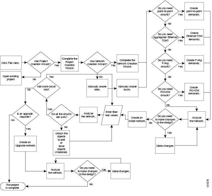
1.3 Cisco TransportPlanner Process Flow
The following stages are used to complete a network design. See Figure 1-1 for the process flow.
1.
2.
3.
4.
5.
6.
7.
8.
Figure 1-1 Cisco TransportPlanner Process Flow
1.4 Planning Traffic in Cisco TransportPlanner
Traffic in Cisco TransportPlanner is defined as an optical path for each pair of nodes requiring a service demand. An optical path is the combined channels between the two nodes. The following list gives definitions for some basic traffic items:
•
–
–
–
–
•
–
–
–
–
–
–
–
–
–
–
•
In P-ring traffic demands, all the demands are used to support traffic topologies similar to bidirectional line switched rings (BLSRs) or multiplex section-shared protection rings (MS-SPRings). Each P-ring demand is between a pair of added/dropped nodes where BLSR-like (or MS-SPRing-like) traffic must exist. The number of circuits is the same for each demand, and is user-specified (from 1 to 40).
In fixed (point-to-point) traffic demands, the set of nodes is restricted to two sites. The number of circuits is user-specified (from 1 to 40).
In any-to-any (ROADM) traffic demands, a minimum of two nodes and a maximum of 40 ROADM nodes are supported. An any-to-any traffic demand allows each node to establish one or more circuits with the other nodes, either as a hub or meshed configuration. In a meshed configuration, each node defined in the set is connected to each other node. This is the most common traffic type. In a hub configuration, the user-defined hub node is connected to each of the other nodes. ROADM circuits have the same protection types and services. The number of circuits is not user-specified and can vary from 0 to 40.
A ROADM demand can have multiple client service types and supports multiple DWDM card interfaces for each client service type. A ROADM demand supports the following routing strategies:
–
–
–
–
1.5 Cisco TransportPlanner Traffic in the Project Explorer Pane
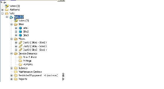
Cisco TransportPlanner Software R8.5 represents all of the user-defined traffic services as a tree view within the Project Explorer pane. The Project Explorer shows all of the open project information, including the networks, the network dependencies, sites, fibers, services, etc. ( Figure 1-2).
Figure 1-2 Project Explorer View
After you analyze a network design, the colors of tree view change according to the error/warning condition of the network design. The icons display as red if there are errors in the network design; orange if there are warnings but no errors; and green of there are no warnings or errors. The icon shows the color of the most severe condition. For more information about analyzing the network, see the "2.4 Analyzing the Network" section on page 2-62.
Right-clicking on certain items in the Project Explorer tree allows you to edit the parameters. Refer to Chapter 2, "Designing Networks with Cisco TransportPlanner" for more information about optical results, the traffic matrix, and editing.
1.5.1 Point-to-Point Traffic Demands
Point-to-point traffic demands appear in the Service Demands > PointToPoint folder in the Project Explorer pane. Each point-to-point traffic demand is categorized by its source and destination site names. All of the point-to-point services between the two sites appear under the designated demand name ( Figure 1-3).
Figure 1-3 Point-to-Point Traffic Demand in the Project Explorer
A point-to-point traffic demand includes the following information:
•
•
1.5.2 P-Ring Traffic Demands
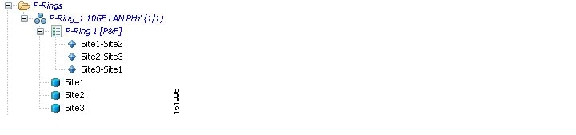
Each protected ring (P-ring) traffic demand appears in the Project Explorer pane under the
Service Demands > P-Rings folder. Figure 1-4 shows an example of a P-ring traffic demand in the Project Explorer.Figure 1-4 P-Ring Traffic Demand in the Project Explorer
All the P-ring channels between each site pair are listed under each P-ring traffic demand. Each demand is labeled with the following information:
•
•
•
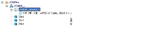
1.5.3 ROADM Traffic Demands
Each ROADM traffic demand appears in the Project Explorer under the Service Demands > ROADMs folder. The ROADM folder contains each defined ROADM demand. You can define more demands for the same ROADM for the same set of nodes. Figure 1-5 shows an example of a ROADM traffic demand.
Figure 1-5 ROADM Traffic Demand in the Project Explorer
In the Project Explorer, each ROADM includes the ROADM demand name and a list of DWDM card types that support the client service types. Protection types appear in parentheses.
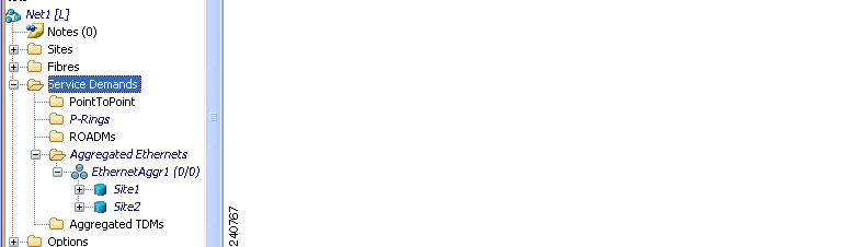
1.5.4 Aggregated Ethernet Demand
Each aggregated ethernet traffic demand appears in the Project Explorer under the Service Demands > Aggregated Ethernet folder. The Aggregated Ethernet folder contains each defined aggregated ethernet demand. Aggregated Ethernet demands are supported on ring and linear traffic subnets. Figure 1-6 shows an example of a aggregated ethernet traffic demand.
Figure 1-6
Aggregated Ethernet Demand in Project Explorer
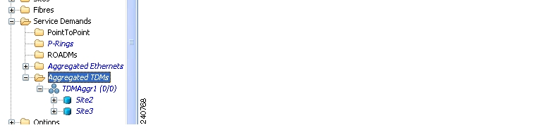
1.5.5 TDM Aggregated Demand
Each TDM aggregated demand appears in the Project Explorer pane under the Service Demands > Aggregated TDMs folder. Figure 1-7 shows an example of a TDM aggregated traffic demand in the Project Explorer.
Figure 1-7
TDM Aggregated Demand in Project Explorer
TDM aggregated demands are supported only on a ring traffic subnet.
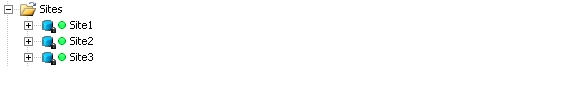
1.6 Auto, Forced, and Locked Parameters
Parameters in Cisco TransportPlanner can be in one of three states:
•
•
•
Figure 1-8 Locked Sites in the Project Explorer View
Depending on the initial state, the network analyzer will:
•
•
![]()
![]()
![]()
![]()
![]()
![]()
![]()
![]()
Posted: Thu Oct 18 08:56:42 PDT 2007
All contents are Copyright © 1992--2007 Cisco Systems, Inc. All rights reserved.
Important Notices and Privacy Statement.