|
|

Table Of Contents
Cisco Transport Controller Operation
CTC Software Installed on the TSC Card
CTC Software Installed on the PC or UNIX Workstation
PC and UNIX Workstation Requirements
Cisco Transport Controller Operation
This chapter describes Cisco Transport Controller (CTC), the CiscoONS15600SDH software interface that is stored on the Timing and Shelf Controller (TSC) card and downloaded to your workstation each time you log into the ONS15600SDH. For CTC set up and login information, refer to the CiscoONS15600SDH Procedure Guide.
Chapter topics include:
•
CTC Software Delivery Methods
•
4.1 CTC Software Delivery Methods
Use CTC to provision and administer the ONS15600SDH. CTC is a Java application that is installed in two locations:
•
•
CTC is stored on the TSC card and downloaded to your workstation each time you log into an ONS15600SDH.
4.1.1 CTC Software Installed on the TSC Card
CTC software is preloaded on the ONS15600SDH TSC cards; therefore, you do not need to install software on the TSC. To upgrade to a newer CTC software version, use the CiscoONS15600SDH Software Upgrade Guide.
You can view the software versions that are installed on one ONS15600SDH by clicking the Maintenance > Software tabs in node view. Click the tabs in network view to display the software versions installed on all the network nodes.
4.1.2 CTC Software Installed on the PC or UNIX Workstation
When you connect to the ONS15600SDH, the TSC card automatically downloads the CTC software to your computer, where it is automatically installed if you have the correct Java Runtime Environment (JRE). The automatic download/installation process ensures that your computer is running the same CTC software version as the TSC you are accessing. The CTC software files are stored in the temporary directory designated by your computer's operating system. You can use the Delete CTC Cache button to remove files stored in the temporary directory. If the files are deleted, they are downloaded the next time you connect to an ONS15600SDH. Downloading the Java archive files, called JAR files, for CTC takes several minutes depending on the bandwidth of the connection between your workstation and the ONS15600SDH. For example, JAR files downloaded from a modem or an Regenerator Section Data Communication Channels (RSDCC) network link will require more time than JAR files downloaded over a LAN connection.
4.2 CTC Installation Overview
To connect to an ONS15600SDH using CTC, enter the ONS15600SDH IP address in the URL field of a web browser, such as Netscape Navigator or Microsoft Internet Explorer. After connecting to an ONS15600SDH, the following events occur automatically:
Note
1.
2.
3.
4.
Each ONS15600SDH can handle up to 16 simultaneous CTC sessions. CTC performance might vary depending upon the volume of activity in each session.
Note
4.3 PC and UNIX Workstation Requirements
To use CTC with an ONS15600SDH, your computer must have a web browser with the correct JRE installed and a modified java.policy file. The correct JRE, Java plugin, and modified java.policy file for the CTC software release are included on the CiscoONS15600SDH software CD.
The requirements depend on the network size. Network size is determined by the following criteria:
•
•
Table4-1 provides the requirements for PCs and UNIX workstations.
4.4 CTC Login
After you have installed CTC, you can log in to a node using your browser. To log in, you must type the node IP address in the URL window. The CTC Login window appears ( Figure4-1).
Figure 4-1 Login Window
The CTC Login window provides the following options to accelerate the login process.
•
•
These options are useful if you want to log in to a node to perform a single task, such as placing a card in or out of service, and do not want to wait while CTC discovers DCC connections and circuits.
4.4.1 Legal Disclaimer
The CTC Login window displays a warning message ( Figure4-1).
The ONS15600SDH allows a user with Superuser privileges to modify the default login warning message and save it to a node using the Provisioning > Security > Legal Disclaimer > HTML tab ( Figure4-2). The login warning message field allows up to 250 characters of text (1600 characters total, including HTML markup).
Figure 4-2 Legal Disclaimer Tab
4.4.2 Login Node Group
Login node groups display nodes that have only an IP connection. After you are logged into CTC, you can create a login node group from the Edit > Preferences menu. Login groups appear in the AdditionalNodes list ( Figure4-1) on the Login window.
For example, if you logged into Node 1, you would see Node 2 and Node 3 because they have DCC connectivity to Node 1. You would not see Nodes 4, 5, and 6 because DCC connections do not exist. To view all six nodes at once, you create a login node group with the IP addresses of Nodes 1, 4, 5, and 6. Those nodes, and all nodes optically connected to them, appear when you select the login group from the Additional Nodes list on the Login window the next time you log in.
4.5 CTC Window
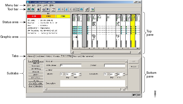
The CTC window appears after you log into an ONS15600SDH. The CTC node view is the first view that appears after you log into an ONS15600SDH ( Figure4-3). The login node is the first node displayed, and it is the home view for the session (accessed by choosing View > Go To Home View).
The CTC window includes a menu bar, toolbar, and a top and bottom pane. The top pane displays status information about the selected objects and a graphic of the current view. The bottom pane displays tabs and subtabs, which you use to view ONS15600SDH information and perform ONS15600SDH provisioning and maintenance. From the default node view window you can display the other two ONS15600SDH views: network and card.
Figure 4-3 CTC Window Elements in the Node View (Default Login View)
4.5.1 Node View
Node view allows you to view and manage one ONS15600SDH node ( Figure4-3). The status area shows the node name; number of critical (CR), major (MJ), and minor (MN) alarms; IP address; session boot date and time; name of the current logged-in user; and user security level.
4.5.1.1 CTC Card Colors
The graphic area of the CTC window depicts the ONS15600SDH shelf assembly. The colors of the cards in the graphic reflect the real-time status of the physical card, slot, and port. Table4-2 describes the node view card colors.
The color of the port in both card and node view indicates the port status. Table4-3 describes the port colors.
4.5.1.2 Node View Card Shortcuts
If you move your mouse over cards in the graphic, popups display additional information about the card including the card type; card status (active or standby); the type of alarm, such as critical, major, and minor (if any); and the alarm profile used by the card. Right-click a card to reveal a shortcut menu that you can use to open, reset, or delete a card. Right-click an empty slot to preprovision a card (that is, provision a slot before installing the card).
4.5.1.3 Node View Tabs
Table4-4 lists the tabs and subtabs available in the node view.
Table 4-4 Node View Tabs and Subtabs
Alarms
Lists current alarms (CR, MJ, MN) for the node and updates them in real time.
—
Conditions
Allows you to retrieve a list of standing conditions on the node.
—
History
Provides a history of node alarms including date, type, and severity of each alarm. The Session subtab displays alarms and events for the current session. The Node subtab displays alarms and events retrieved from a fixed-size log on the node.
Session, Node
Circuits
Allows you to create, delete, edit, and reroute circuits.
Circuits, Rolls
Provisioning
Allows you to provision the ONS15600SDH node.
General, Network, Protection, MS-SPRing1 , Security, SNMP2 , DCC/GCC3 , Timing, Alarm Behavior, Alarm Extenders
Inventory
Provides inventory information (part number, serial number, Common Language Equipment Identification [CLEI] codes) for cards installed in the node. Allows you to delete and reset cards, and provision the user code (a 20-character ASCII string stored in nonvolatile memory so that it is not lost when the unit is moved or stored as a spare).
—
Maintenance
Allows you to perform maintenance tasks for the node.
Database, Protection, Diagnostic, MS-SPRing1, Software, Timing, Audit, Routing Table, Test Access, Alarm Extenders, Preferred Copy
1 MS-SPRing = multiplex section-shared protection ring
2 SNMP = Simple Network Management Protocol
3 DCC/GCC = data communications channel/general communications channel
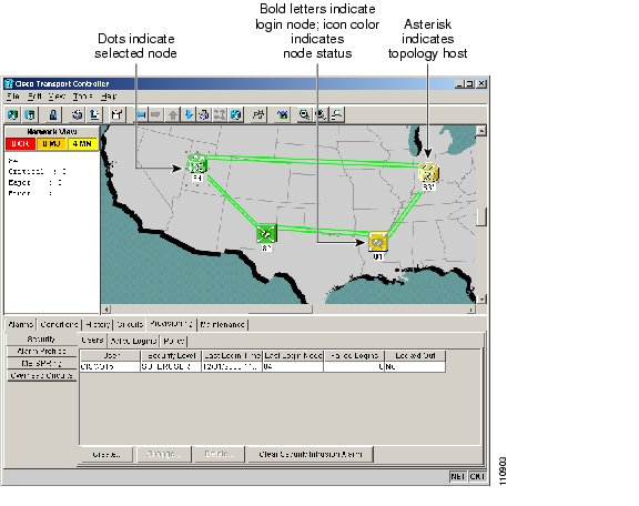
4.5.2 Network View
Network view allows you to view and manage ONS15600SDH nodes, ONS 15454 SDH nodes that have DCC connections to the node that you logged into, and any login node groups you have selected ( Figure4-4).
Note
To access network view, choose View > Go To Network View or click the up arrow in the CTC toolbar.
The graphic area displays a background image with colored node icons. A Superuser can set up the logical network view feature, which enables each user to see the same network view.
The node icon colors indicate the node status ( Table4-5). Lines show DCC connections between the nodes. Selecting a node or span in the graphic area displays information about the node and span in the status area.
Figure 4-4 Network Displayed in CTC Network View
Table4-5 lists the node status colors.
Table4-6 lists the tabs and subtabs available in the network view.
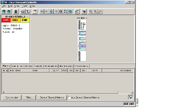
4.5.3 Card View
Card view displays information about individual ONS15600SDH cards. Use this window to perform card-specific maintenance and provisioning ( Figure4-5). To access card view, select a card and click the down arrow in the toolbar, or double-click the card.
A graphic of the selected card and ports is shown in the CTC graphic area. The status area displays the node name, slot, card type, number of alarms, equipment type, and the card status (active or standby). The information displayed and the actions you can perform depend on the card.
Note
Figure 4-5 CTC Card View Showing an STM-64 Card
Use the card view tabs and subtabs, shown in Table4-7, to provision and manage the ONS15600SDH. The subtabs, fields, and information displayed under each tab depend on the card type selected.
1 MS = Multiplex Section
2 QoS = Quality of Service
4.6 CTC Card Reset
You can reset the ONS15600SDH cards by using the hard-reset or soft-reset commands in CTC, or by physically reseating a card (card pull). From the node view, select a card and right-click to open a menu with the hard-reset and soft-reset commands.
A soft reset on the TSC reboots the TSC and reloads the operating system and the application software. A CTC hard reset temporarily removes power from the TSC and clears all buffer memory. You can apply a CTC soft reset to either an active or standby TSC without affecting traffic, but you should only perform a hard reset (or a card pull) on a standby TSC. If you need to perform a CTC hard reset or card pull on an active TSC, put the TSC into standby mode first by performing a soft reset.
A soft reset on an optical card with an active port in a 1+1 protection group will result in a loss of all DCC traffic terminated or tunneled on the active port for the duration of the reset time. A soft reset of an optical card with a standby port in a 1+1 protection group will not affect DCC traffic. A CTC hard reset of an optical card causes a switch to the protect card.
4.7 TSC Card Database
Each TSC card hosts a separate database; therefore, the protect card's database is available if the database on the working TSC fails. After a database change, there might be a 30-second interval before the TSC starts writing the data to the flash drive. If you reset the active TSC immediately after a database change, the change could be lost.
You can also store a backup version of the database on the workstation running CTC. This operation should be part of a regular ONS15600SDH maintenance program at approximately weekly intervals and should also be completed when preparing an ONS15600SDH for a software upgrade or a pending natural disaster, such as a flood.
Note
Note
4.8 Software Load Revert
Before you upgrade to a later software release, you must create a database backup. If you later need to restore the original working software load from the protect software load, CTC displays a prompt requesting the location of the backup. Any provisioning performed with the later software release will be lost when the earlier software release backup is restored.
Note
![]()
![]()
![]()
![]()
![]()
![]()
![]()
![]()
Posted: Thu Feb 26 17:35:33 PST 2004
All contents are Copyright © 1992--2004 Cisco Systems, Inc. All rights reserved.
Important Notices and Privacy Statement.