|
|

Table Of Contents
Cisco ONS 15600 SDH TL1 Test Access
Obtaining Technical Assistance
Obtaining Additional Publications and Information
Quick Start Guide
Cisco ONS 15600 SDH TL1 Test Access
1 Test Access
The test access (TACC) feature allows a third-party Broadband Remote Test Unit (BRTU) to create nonintrusive test access points (TAPs) to monitor the circuits on the ONS 15600 SDH for errors. The test access feature also allows the circuit to be split (intrusive), so that the transmission paths can be tested for bit errors via the use of various bit test patterns. The two BRTUs supported by the ONS 15600 SDH are the Hekimian/Spirent BRTU-93 (6750) and the TTC/Acterna Centest 650.
The test access functionality provides TL1 commands for creating and deleting TAPs, connecting or disconnecting TAPs to circuit cross-connects, and changing the mode of test access on the ONS 15600 SDH. You can view test access information in CTC; in node view click the Maintenance > Test Access tabs.
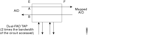
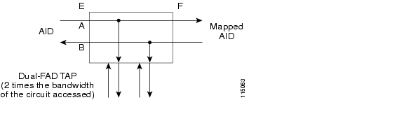
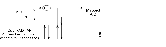
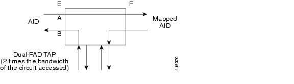
A TAP provides the capability to connect the circuit under test to a BRTU. This connection initially provides in-service monitoring capability to permit the tester to determine that the circuit under test is idle. The monitor connection should not disturb the circuit under test. The access point and remote test unit (RTU) also provide the capability of splitting a circuit under test. A split consists of breaking the transmission path of the circuit under test. This is done out of service. The two sides of the access point are called the Equipment (E) and Facility (F) directions. For a 4-wire or 6-wire circuit, the transmission pairs within the access point are defined as the A and B pairs. The circuit under test should be wired into the access point so the direction of transmission on the A pair is from E to F, and the transmission direction for the B pair is from F to E ( Figure 1).
Figure 1 Circuit with No Access (Dual FAD TAP)
A dual facility access digroup (FAD) TAP uses twice the bandwidth of the circuit under test. This can be specified by the TAPTYPE parameter as shown in ED-<MOD2> command syntax in the "ED-<rr>" section. The values are SINGLE/DUAL. It defaults to DUAL.
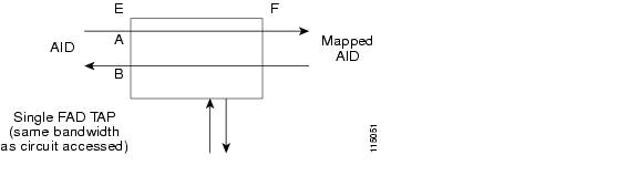
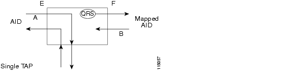
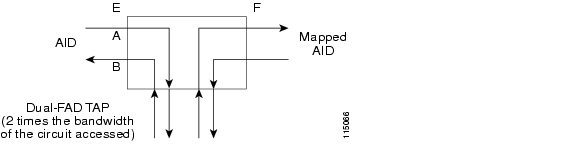
A single FAD TAP uses half the bandwidth as that of the dual FAD, that is, it will use the same bandwidth as the circuit accessed for the TAP creation. This can be specified by the TAPTYPE parameter as shown in the "ED-<rr>" section. The values are SINGLE/DUAL. The MONEF, SPLTEF, and LOOPEF modes are not supported by SINGLE FAD TAPs ( Figure 2).
Figure 2 Circuit with No Access (Single FAD TAP)
2 TL1 Interface Commands
TL1 supports commands to create, delete, connect, change, retrieve, and disconnect TAPs.
TAP Creation/Deletion
ED-<rr>
The edit command (ED-<rr>) is used to change an existing Port/VC to a TAP.
ED- {VC4| VC44C| VC48C| VC416C|
VC464C}:[<TID>]:<AID>:<CTAG>[:::TACC=<TACC>],[TAPTYPE=<TAPTYPE>];
Edit an existing Port/ VC and change it to a TAP so it can be used when requesting TACC connections. This includes an optional parameter TACC=n that defines the port/VC as a test access point with a selected unique TAP number. This TAP number will be used when requesting test access connections to circuit cross-connects under test. The TAP creation will fail if the port/VCn already has a cross-connect on it.
The TAPTYPE parameter value is SINGLE or DUAL. The MONEF, SPLTEF, and LOOPEF modes are not supported by single FAD TAPs. It defaults to DUAL.
Note
This command generates a REPT DBCHG message.
Note
Note
The following apply to TAP numbers:
•
•
•
ED-VC4n
When an ED-VC4n is executed for a TACC it assigns the VC path for the first two-way test access connection and VC+1 as the second two-way connection. Similarly, for VC42c, VC43c, VC44c, VC48c, and VC416c, the next consecutive VC of same width is chosen. The TAP creation fails if either of the consecutive VC's are not available. The command in Example 1 creates a TAP on VC4-5-1-1 and VC4-5-1-2.
Example 1 Creating a Single TAP
ED-VC4::VC4-5-1-1:12:::TACC=4;

   DV9-99 1970-01-02 03:16:11
M  12 COMPLD
;
Note
The command in Example 2 creates a VC48c DUAL TAP on VC4-6-1-1 and VC4-6-1-25.
Example 2 Creating a Dual TAP
ED-VC48C::VC4-6-1-1:12:::TACC=5;

   DV9-99 1970-01-02 03:16:11
M  12 COMPLD
;
Note
TAP Connections
CONN-TACC-<rr>
The CONN-TACC command (CONN-TACC-<rr>) is used to make a connection between the TAP and the circuit or cross-connect under test.
CONN-TACC-{VC4| VC44C| VC48C| VC416C| VC464C}:[<TID>]:<AID>:<CTAG>::<TAP>:MD=<MD>;Connect the port/VC4n defined by <AID> to the port/VC4n defined by the <TAP> number. The Mode of Test Access to the circuit/cross-connect is specified by <MD>. The mode can be monitor (MONEF), split (SPLTEF), or loop (LOOPEF). The modes are described in the "Test Access Configurations" section.
Note
Note
Table 1 shows the error codes supported for the CONN-TACC-<rr> command.
An example of the CONN-TACC-<rr> command is provided in Example 3 Table 1 Table 1.
Example 3 CONN-TACC-<rr> Command Example
CONN-TACC-E1::FAC-1-3:12::1:MD=MONE;

   DV9-99 1970-01-02 02:51:54
M  12 COMPLD
   1
;
This creates a connection between TAP with number 1 and the port/facility FAC-1-3 with access mode as MONE. The various modes are explained in detail in the "Test Access Mode Definitions" section.
Change Access Mode
CHG-ACCMD-<rr>
CHG-ACCMD- {VC4| VC44C| VC48C| VC416C| VC464C}:[<TID>]:<TAP>:<CTAG>::<MD>;Change the type of test access. This might be a change from monitoring the data to inserting data into the VC. This command can only be applied to an existing TAP connection. If an existing connection does not exist, a RTEN error is returned.
Table 2 shows the error codes supported for the CHG-ACCMD-<rr> command.
Table 2 Error Codes Supported for the CHG-ACCMD-<rr> Command
SRCN
REQUESTED CONDITION ALREADY EXISTS
SRAC
REQUESTED ACCESS CONFIGURATION IS INVALID
RTEN
REQUESTED TAP DOES NOT EXIST
An example of the CHG-ACCMD-<rr> command is provided in Example 4 Table 1 Table 1.
Example 4 CHG-ACCMD-<rr> Command Example
CHG-ACCMD-E1::1:12::LOOPE;

   DV9-99 1970-01-02 02:59:43
M  12 COMPLD
;
Note
Note
Note
Retrieving TAP Information
RTRV-<rr>
RTRV- {VC4| VC44C| VC48C| VC416C| VC464C}:[<TID>]:<AID>:<CTAG>;These commands are modified to include the return of a TAP number if the requested AID is defined as a TAP. An optional TACC=<TAPNUMBER> will be displayed in the output list if the requested AID is defined as a TAP. The TAPTYPE is supported starting with ONS 15600 SDH R1.4.
An example of the RTRV-<rr> command is provided in Example 5.
Example 5 RTRV-<rr> Command Example
RTRV-E1::FAC-1-1:D;

   VA454E-96 2003-04-24 20:06:46
M  D COMPLD
"FAC-1-1::LINECDE=HDB3,FMT=E1-MF,TACC=1,TAPTYPE=DUAL,SOAK=32:OOS,"
;
The parameters supported by the RTRV-<rr> command are listed in Table 3.
Disconnect a TAP
DISC-TACC
DISC-TACC:[<TID>]:<TAP>:<CTAG>;Disconnect the TAP and put the connection back to its original state (no access).
Table 4 shows the error codes supported for the CHG-ACCMD-<rr> command.
Table 4 Error Codes Supported by the DISC-TACC Command
SADC
ALREADY DISCONNECTED
SRTN
UNABLE TO RELEASE TAP
An example of the DISC-TACC command is provided in Example 6.
Example 6 DISC-TACC Command Example
DISC-TACC::1:12;

   DV9-99 1970-01-02 02:59:43
M  12 COMPLD
;
Note
Note
3 Test Access Configurations
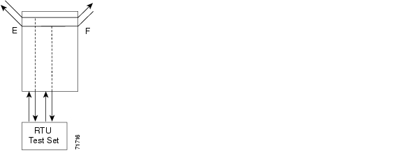
Figure 3 shows a single node configuration.
Figure 3 Single Node View (Node 1)
To configure a single-node TAP, use the following sample code:
ED-VC4::VC4-1-1-1:90:::TACC=1;This code changes VC4 1 and VC4 2 on Slot 1 to a TAP. The CTAG is 90. This command also sets the TAP number to 1.
To connect the AID to the TACC defined by TAP 1 on the E side, use the following code (where the CTAG is 91)
CONN-TACC-VC4::<AID-for-E-or-F-depending-on-MD>:91::1:MONE
Note
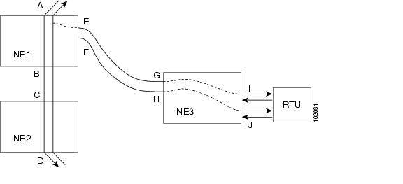
Figure 4 Multi-node View (MONE Example)
To create a multi-node configuration:
Step 1
ENT-CRS-VC::<AID I-G>:100::2WAY;This is a connection, not a TAP. The CTAG is 100.
Step 2
ENT-CRS-VC::<AID J-H>:101::2WAY;This second connection is not a TAP.
Step 3
ED-VC4::VC4-1-1-1:D:::TACC=4;This creates a TAP with VC4-1-1-1 and VC4-1-1-2 through NE1. The TAP number assigned is 4.
Step 4
CONN-TACC-VC::<AID A or B>:102::4:<MD>
Note
4 Test Access Mode Definitions
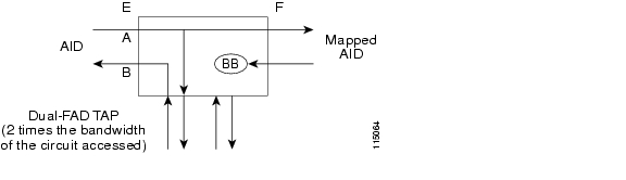
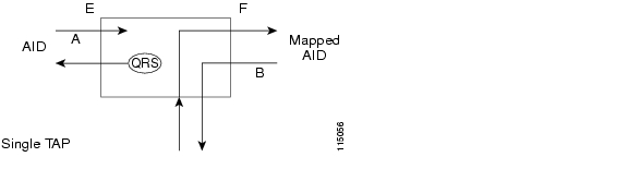
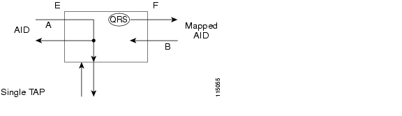
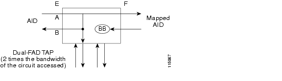
The following diagrams show what the different test access modes <MD> refer to. Figure 5 shows a circuit with no access (DUAL FAD TAP), Figure 6 shows a circuit with no access (SINGLE FAD TAP), followed by all the modes. The QRS might be generated by an outside source, that is, the empty connection of the BRTU.
Intrusive and Nonintrusive Modes
MONE, MONF, and MONEF access modes are non-service-affecting and can be applied to an IS (in service) port.
LOOPE, LOOPF, SPLTE, SPLTF, SPLTEF, SPLTA, SPLTB, and SPLTAB access modes are intrusive and can only be applied to a circuit/port that is in the OOS_MT (out of service, maintenance) state. The network element (NE) will change the state of the circuit under test to OOS_MT during the period of TACC and restore it to the original state after the connection between the TAP and the circuit is dropped.
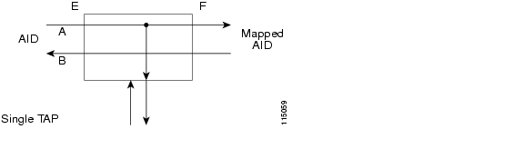
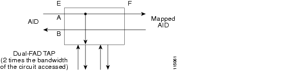
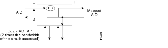
Figure 5 Circuit with No Access (DUAL FAD TAP)
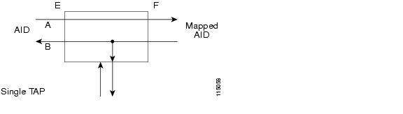
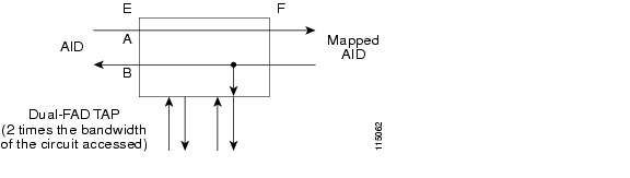
Figure 6 Circuit with No Access (SINGLE FAD TAP)
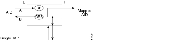
MONE
Monitor E (MONE) indicates a monitor connection provided from the FAD to the A transmission path of the accessed circuit ( Figure 7 and Figure 8). This is a nonintrusive mode.
Figure 7 MONE Access SINGLE TAP
Figure 8 MONE Access DUAL TAP
MONF
Monitor F (MONF) indicates that the FAD is providing a monitor connection to the B transmission path of the accessed circuit ( Figure 9 and Figure 10). This is a nonintrusive mode.
Figure 9 MONF Access SINGLE TAP
Figure 10 MONF Access DUAL TAP
Note
MONEF
Monitor EF (MONEF) is a monitor connection provided from the FAD 1 (odd pair) to a dual facility access digroup (DFAD) to the A transmission path, and from FAD2 (even pair) of the same DFAD to the B transmission path of the accessed circuit ( Figure 11). This is a nonintrusive mode.
MONEF for T3 (DS3 HCDS) indicates that the odd pair of a FAP is providing a monitor connection to the A transmission path and from the even pair of a facility access path (FAP) to the B transmission path of the accessed circuit.
Figure 11 MONEF Access DUAL TAP
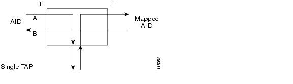
SPLTE
Split E (SPLTE) splits both the A and B paths and connects the E side of the accessed circuit to the FAD ( Figure 12 and Figure 13).
Figure 12 SPLTE Access SINGLE TAP
Figure 13 SPLTE Access DUAL TAP
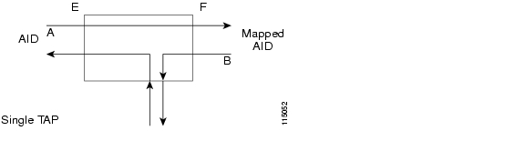
SPLTF
Split F (SPLTF) splits both the A and B paths and connects the F side of the accessed circuit to the FAD ( Figure 14 and Figure 15).
Figure 14 SPLTF Access SINGLE TAP
Figure 15 SPLTF Access DUAL TAP
SPLTEF
Split EF (SPLTEF) for T1 (DS1 HCDS) splits both the A and B paths, connects the E side of the accessed circuit to FAD1 and the DFAD pair, and connects the F side to the FAD 2 of the same DFAD pair. SPLTEF for T3 (DS3 HCDS) splits both the A and B paths and connect the E side of the accessed circuit to the odd pair of the FAP and the F side to the even pair of the FAP ( Figure 16).
Figure 16 SPLTEF Access DUAL TAP
LOOPE
Loop E (LOOPE) splits both the A and B paths, connects the incoming line from the E direction to the outgoing line in the E direction, and connects this looped configuration to the FAD ( Figure 17 and Figure 18). Loop E and F modes are basically identical to the SPLT E and F modes except that the outgoing signal is the incoming signal and not the signal from the remote test unit (RTU).
Figure 17 LOOPE Access SINGLE TAP
Figure 18 LOOPE Access DUAL TAP
LOOPF
Loop F (LOOPF) splits both the A and B paths, connects the incoming line from the F direction to the outgoing line in the F direction, and connects this looped configuration to the FAD ( Figure 19 and Figure 20).
Figure 19 LOOPF Access SINGLE TAP
Figure 20 LOOPF Access DUAL TAP
SPLTA
Split A (SPLTA) indicates that a connection is provided from both the E and F sides of the A transmission path of the circuit under test to the FAD and the A transmission path is split ( Figure 21 and Figure 22). These modes are similar to the Split E and F modes, except the signals are sent to the RTU, not the NE signal configuration.
Figure 21 SPLTA Access SINGLE TAP
Figure 22 SPLTA Access DUAL TAP
SPLTB
Split B (SPLTB) indicates that a connection is provided from both the E and F sides of the B transmission path of the circuit under test to the FAD and the B transmission path is split ( Figure 23 and Figure 24).
Figure 23 SPLTB Access SINGLE TAP
Figure 24 SPLTB Access DUAL TAP
5 Unmapped AID TAP Connections
The Cisco ONS 15600 SDH also supports connections to unmapped AIDs (unmapped circuits). The TAPs can be connected to an unmapped AID (an AID that does not have a cross-connect on it). The access modes supported are MONE, SPLTE, and LOOPE. Example 7 creates a TAP on VC4-5-1-1. Table 5 describes the modes and the circuit types that support them.
Example 7 Sample TAP on VC4-5-1-1
ED-VC4::VC4-5-1-1:12:::TACC=1;

   DV9-99 1970-01-02 03:16:11
M  12 COMPLD
;
Example 8 creates an unmapped AID connection with a MONE access mode. VC-5-1-3 does not have a cross-connect on it. VC-5-1-3 becomes unusable until the connection is disconnected by the DISC-TACC command.
Example 8 Sample Unmapped AID Connection with MONE Access Mode
CONN-TACC-VC4::VC4-5-1-3:12::1:MD=MONE;

   DV9-99 1970-01-02 02:51:54
M  12 COMPLD
   1
;
Note
Note
6 Parameter Types
TACC_MODE
The test access mode parameter values are described in Table 6.
MOD_TACC
The test access modifier parameter values are provided in Table 7.
Table 7 MOD_TACC Parameter Values
VC44C
VC44C path
VC464C
VC464C path
VC48C
VC48C path
VC4
VC4 path
VC416C
VC416C path
TAPTYPE
The test access path/point type parameter values are provided in Table 8.
Table 8 TAPTYPE Parameter Values
DUAL
Dual-FAD type
SINGLE
Single-FAD type
7 Test Access Terminology
Table 9 lists test access terminology and definitions. Path naming conventions are listed in Table 10.
8 Obtaining Documentation
Cisco documentation and additional literature are available on Cisco.com. Cisco also provides several ways to obtain technical assistance and other technical resources. These sections explain how to obtain technical information from Cisco Systems.
Cisco.com
You can access the most current Cisco documentation on the World Wide Web at this URL:
http://www.cisco.com/univercd/home/home.htm
You can access the Cisco website at this URL:
International Cisco websites can be accessed from this URL:
http://www.cisco.com/public/countries_languages.shtml
Ordering Documentation
You can find instructions for ordering documentation at this URL:
http://www.cisco.com/univercd/cc/td/doc/es_inpck/pdi.htm
You can order Cisco documentation in these ways:
•
http://www.cisco.com/en/US/partner/ordering/index.shtml
•
9 Documentation Feedback
You can submit e-mail comments about technical documentation to bug-doc@cisco.com.
You can submit comments by using the response card (if present) behind the front cover of your document or by writing to the following address:
Cisco Systems
Attn: Customer Document Ordering
170 West Tasman Drive
San Jose, CA 95134-9883We appreciate your comments.
10 Obtaining Technical Assistance
For all customers, partners, resellers, and distributors who hold valid Cisco service contracts, the Cisco Technical Assistance Center (TAC) provides 24-hour-a-day, award-winning technical support services, online and over the phone. Cisco.com features the Cisco TAC website as an online starting point for technical assistance. If you do not hold a valid Cisco service contract, please contact your reseller.
Cisco TAC Website
The Cisco TAC website provides online documents and tools for troubleshooting and resolving technical issues with Cisco products and technologies. The Cisco TAC website is available 24 hours a day, 365 days a year. The Cisco TAC website is located at this URL:
Accessing all the tools on the Cisco TAC website requires a Cisco.com user ID and password. If you have a valid service contract but do not have a login ID or password, register at this URL:
http://tools.cisco.com/RPF/register/register.do
Opening a TAC Case
Using the online TAC Case Open Tool is the fastest way to open P3 and P4 cases. (P3 and P4 cases are those in which your network is minimally impaired or for which you require product information.) After you describe your situation, the TAC Case Open Tool automatically recommends resources for an immediate solution. If your issue is not resolved using the recommended resources, your case will be assigned to a Cisco TAC engineer. The online TAC Case Open Tool is located at this URL:
http://www.cisco.com/tac/caseopen
For P1 or P2 cases (P1 and P2 cases are those in which your production network is down or severely degraded) or if you do not have Internet access, contact Cisco TAC by telephone. Cisco TAC engineers are assigned immediately to P1 and P2 cases to help keep your business operations running smoothly.
To open a case by telephone, use one of the following numbers:
Asia-Pacific: +61 2 8446 7411 (Australia: 1 800 805 227)
EMEA: +32 2 704 55 55
USA: 1 800 553-2447For a complete listing of Cisco TAC contacts, go to this URL:
http://www.cisco.com/warp/public/687/Directory/DirTAC.shtml
TAC Case Priority Definitions
To ensure that all cases are reported in a standard format, Cisco has established case priority definitions.
Priority 1 (P1)—Your network is "down" or there is a critical impact to your business operations. You and Cisco will commit all necessary resources around the clock to resolve the situation.
Priority 2 (P2)—Operation of an existing network is severely degraded, or significant aspects of your business operation are negatively affected by inadequate performance of Cisco products. You and Cisco will commit full-time resources during normal business hours to resolve the situation.
Priority 3 (P3)—Operational performance of your network is impaired, but most business operations remain functional. You and Cisco will commit resources during normal business hours to restore service to satisfactory levels.
Priority 4 (P4)—You require information or assistance with Cisco product capabilities, installation, or configuration. There is little or no effect on your business operations.
11 Obtaining Additional Publications and Information
Information about Cisco products, technologies, and network solutions is available from various online and printed sources.
•
http://www.cisco.com/go/marketplace/
•
http://cisco.com/univercd/cc/td/doc/pcat/
•
•
•
http://www.cisco.com/go/iqmagazine
•
•
![]()
![]()
![]()
![]()
![]()
![]()
![]()
![]()
Posted: Mon Aug 22 20:05:24 PDT 2005
All contents are Copyright © 1992--2005 Cisco Systems, Inc. All rights reserved.
Important Notices and Privacy Statement.