|
|

Table Of Contents
Understanding Link Aggregation
EtherChannel Configuration Example
POS Channel Configuration Example
Understanding Encapsulation over EtherChannel or POS Channel
Configuring Encapsulation over EtherChannel or POS Channel
Encapsulation over EtherChannel Example
Monitoring and Verifying EtherChannel and POS
Understanding Link Aggregation Control Protocol
Configuring Link Aggregation
This chapter describes how to configure link aggregation for the ML-Series cards, both EtherChannel and packet-over-SONET/SDH (POS) channel. For additional information about the Cisco IOS commands used in this chapter, refer to the Cisco IOS Command Reference publication.
This chapter contains the following major sections:
•
Understanding Link Aggregation
•
•
•
Understanding Link Aggregation
The ML-Series card offers both EtherChannel and POS channel. Traditionally EtherChannel is a trunking technology that groups together multiple full-duplex IEEE 802.3 Ethernet interfaces to provide fault-tolerant high-speed links between switches, routers, and servers. EtherChannel forms a single higher bandwidth routing or bridging endpoint and was designed primarily for host-to-switch connectivity. The ML-Series card extends this link aggregation technology to bridged POS interfaces. POS channel is only supported with LEX encapsulation.
Link aggregation provides the following benefits:
•
•
•
Port channel is a term for both POS channel and EtherChannel. The port channel interface is treated as a single logical interface although it consists of multiple interfaces. Each port channel interfaces consists of one type of interface, either Fast Ethernet, Gigabit Ethernet, or POS. You must perform all port channel configurations on the port channel (EtherChannel or POS channel) interface rather than on the individual member Ethernet or POS interfaces. You can create the port channel interface by entering the interface port-channel interface configuration command.
Note
Port channel connections are fully compatible with IEEE 802.1Q trunking and routing technologies. IEEE 802.1Q trunking can carry multiple VLANs across a port channel.
Each ML100T-12, ML100X-8, or ML1000-2 card supports one POS channel, a port channel made up of the two POS ports. A POS channel combines the two POS port capacities into a maximum aggregate capacity of STS-48c or VC4-16c.
Each ML100T-12 supports up to six FECs and one POS channel. Each ML100X-8 supports up to four FECs and one POS channel. A maximum of four Fast Ethernet ports can bundle into one Fast Ethernet Channel (FEC) and provide bandwidth scalability up to 400-Mbps full-duplex Fast Ethernet.
Each ML1000-2 supports up to two port channels, including the POS channel. A maximum of two Gigabit Ethernet ports can bundle into one Gigabit Ethernet Channel (FEC) and provide 2-Gbps full-duplex aggregate capacity on the ML1000-2.
Caution
Caution
Note
Note
Note
Configuring EtherChannel
You can configure an FEC or a GEC by creating an EtherChannel interface (port channel) and assigning a network IP address. All interfaces that are members of a FEC or a GEC should have the same link parameters, such as duplex and speed.
To create an EtherChannel interface, perform the following procedure, beginning in global configuration mode:
For information on other configuration tasks for the EtherChannel, refer to the
Cisco IOS Configuration Fundamentals Configuration Guide.To assign Ethernet interfaces to the EtherChannel, perform the following procedure, beginning in global configuration mode:
EtherChannel Configuration Example
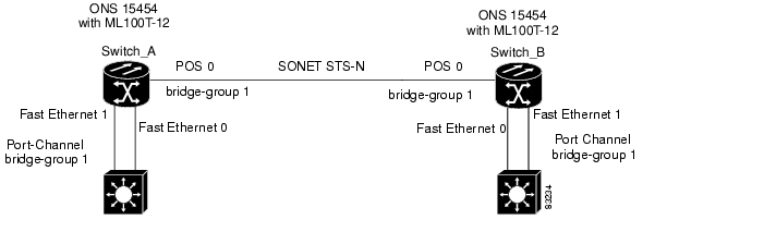
Figure 10-1 shows an example of EtherChannel. The associated commands are provided in Example 10-1 (Switch A) and Example 10-2 (Switch B).
Figure 10-1 EtherChannel Example
Example 10-1 Switch A Configuration
hostname Switch A!bridge 1 protocol ieee!interface Port-channel 1no ip addressbridge-group 1hold-queue 150 in!interface FastEthernet 0no ip addresschannel-group 1!interface FastEthernet 1no ip addresschannel-group 1!interface POS 0no ip routingno ip addresscrc 32bridge-group 1pos flag c2 1Example 10-2 Switch B Configuration
hostname Switch B!bridge 1 protocol ieee!interface Port-channel 1no ip routingno ip addressbridge-group 1hold-queue 150 in!interface FastEthernet 0no ip addresschannel-group 1!interface FastEthernet 1no ip addresschannel-group 1!interface POS 0no ip addresscrc 32bridge-group 1pos flag c2 1!Configuring POS Channel
You can configure a POS channel by creating a POS channel interface (port channel) and optionally assigning an IP address. All POS interfaces that are members of a POS channel should have the same port properties and be on the same ML-Series card.
Note
To create a POS channel interface, perform the following procedure, beginning in global configuration mode:
Caution
To assign POS interfaces to the POS channel, perform the following procedure, beginning in global configuration mode:
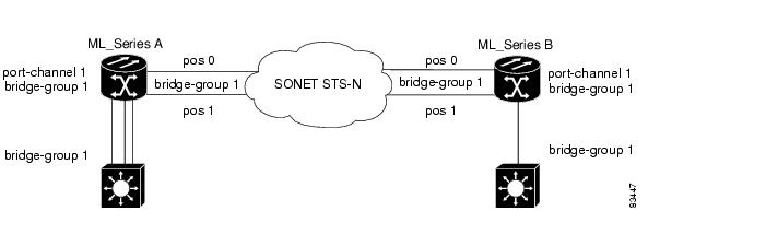
POS Channel Configuration Example
Figure 10-2 shows an example of POS channel configuration. The associated code is provided in Example 10-3 (Switch A) and Example 10-4 (Switch B).
Figure 10-2 POS Channel Example
Example 10-3 Switch A Configuration
bridge irbbridge 1 protocol ieee!!interface Port-channel1no ip addressno keepalivebridge-group 1!interface FastEthernet0no ip addressbridge-group 1!interface POS0no ip addresschannel-group 1crc 32pos flag c2 1!interface POS1no ip addresschannel-group 1crc 32pos flag c2 1Example 10-4 Switch B Configuration
bridge irbbridge 1 protocol ieee!!interface Port-channel1no ip addressno keepalivebridge-group 1!interface FastEthernet0no ip addressbridge-group 1!interface POS0no ip addresschannel-group 1crc 32pos flag c2 1!interface POS1no ip addresschannel-group 1crc 32pos flag c2 1Understanding Encapsulation over EtherChannel or POS Channel
When configuring encapsulation over FEC, GEC, or POS, be sure to configure IEEE 802.1Q on the port-channel interface, not its member ports. However, certain attributes of port channel, such as duplex mode, need to be configured at the member port levels. Also make sure that you do not apply protocol-level configuration (such as an IP address or a bridge group assignment) to the member interfaces. All protocol-level configuration should be on the port channel or on its subinterface. You must configure IEEE 802.1Q encapsulation on the partner system of the EtherChannel as well.
Configuring Encapsulation over EtherChannel or POS Channel
To configure encapsulation over the EtherChannel or POS channel, perform the following procedure, beginning in global configuration mode:
Encapsulation over EtherChannel Example
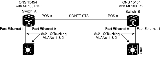
Figure 10-3 shows an example of encapsulation over EtherChannel. The associated code is provided in Example 10-5 (Switch A) and Example 10-6 (Switch B).
Figure 10-3 Encapsulation over EtherChannel Example
This encapsulation over EtherChannel example shows how to set up two ONS 15454s with ML100T-12 cards (Switch A and Switch B) to interoperate with two switches that also support IEEE 802.1Q encapsulation over EtherChannel. To set up this example, use the configurations in the following sections for both Switch A and Switch B.
Example 10-5 Switch A Configuration
hostname Switch A!bridge irbbridge 1 protocol ieeebridge 2 protocol ieee!interface Port-channel1no ip addresshold-queue 150 in!interface Port-channel1.1encapsulation dot1Q 1 nativebridge-group 1!interface Port-channel1.2encapsulation dot1Q 2bridge-group 2!interface FastEthernet0no ip addresschannel-group 1!interface FastEthernet1no ip addresschannel-group 1!interface POS0no ip addresscrc 32pos flag c2 1!interface POS0.1encapsulation dot1Q 1 nativebridge-group 1!interface POS0.2encapsulation dot1Q 2bridge-group 2Example 10-6 Switch B Configuration
hostname Switch B!bridge irbbridge 1 protocol ieeebridge 2 protocol ieee!interface Port-channel1no ip addresshold-queue 150 in!interface Port-channel1.1encapsulation dot1Q 1 nativebridge-group 1!interface Port-channel1.2encapsulation dot1Q 2bridge-group 2!interface FastEthernet0no ip addresschannel-group 1!interface FastEthernet1no ip addresschannel-group 1!interface POS0no ip addresscrc 32pos flag c2 1!interface POS0.1encapsulation dot1Q 1 nativebridge-group 1!interface POS0.2encapsulation dot1Q 2bridge-group 2!Monitoring and Verifying EtherChannel and POS
After FEC, GEC, or POS is configured, you can monitor its status using the show interfaces port-channel command.
Example 10-7 show interfaces port-channel Command
Router# show int port-channel 1Port-channel1 is up, line protocol is upHardware is FEChannel, address is 0005.9a39.6634 (bia 0000.0000.0000)MTU 1500 bytes, BW 200000 Kbit, DLY 100 usec,reliability 255/255, txload 1/255, rxload 1/255Encapsulation ARPA, loopback not setKeepalive set (10 sec)Unknown duplex, Unknown SpeedARP type: ARPA, ARP Timeout 04:00:00No. of active members in this channel: 2Member 0 : FastEthernet0 , Full-duplex, Auto SpeedMember 1 : FastEthernet1 , Full-duplex, Auto SpeedLast input 00:00:01, output 00:00:23, output hang neverLast clearing of "show interface" counters neverInput queue: 0/150/0/0 (size/max/drops/flushes); Total output drops: 0Queueing strategy: fifoOutput queue :0/80 (size/max)5 minute input rate 0 bits/sec, 0 packets/sec5 minute output rate 0 bits/sec, 0 packets/sec820 packets input, 59968 bytesReceived 0 broadcasts, 0 runts, 0 giants, 0 throttles0 input errors, 0 CRC, 0 frame, 0 overrun, 0 ignored0 watchdog, 0 multicast0 input packets with dribble condition detected32 packets output, 11264 bytes, 0 underruns0 output errors, 0 collisions, 0 interface resets0 babbles, 0 late collision, 0 deferred0 lost carrier, 0 no carrier0 output buffer failures, 0 output buffers swapped out.Understanding Link Aggregation Control Protocol
In Software Release 8.0.0, ML100T-12, ML1000-2, ML100T-8, and CE-100T-8 cards can utilize the link aggregation control protocol (LACP) to configure and control link aggregation. LACP provides the ability to continuously monitor the configuration and take appropriate reconfiguration actions.
The cards' ports can also transport a signal transparently (that is, without intervention or termination) when LACP is not configured for the port.
Passive Mode and Active Mode
LACP operates in two modes: active and passive mode. In the active mode, LACP packets are transmitted unconditionally. Whereas, in passive mode LACP starts transmitting packets only after it receives a LACP packet from the peer device.
LACP Functions
LACP performs the following functions in the system:
•
•
•
•
In addition, LACP provides the following benefits:
•
•
•
LACP Parameters
LACP utilizes the following parameters to control aggregation:
System Identifier—A unique identification assigned to each system. It is the concatenation of the system priority and a globally administered individual MAC address.
Port Identification—A unique identifier for each physical port in the system. It is the concatenation of the port priority and the port number.
Port Capability Identification—An integer, called a key, that identifies one port's capability to aggregate with another port. There are two types of key: administrative and operational. An administrative key is configured by the network administrator, and an operational key is assigned by LACP to a port based on its aggregation capability.
Aggregation Identifier—A unique integer that is assigned to each aggregator and is used for identification within the system.
LACP Usage Scenarios
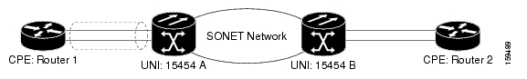
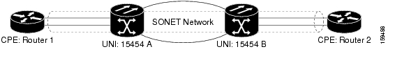
In Software Release 8.0.0, LACP functions on CE-Series cards and ML-Series cards in two modes: termination mode and transparent mode. For example, in Figure 10-4, the topology shows a CPE router device connected to an ML-Series card on the ONS 15454.
Figure 10-4 LACP Topology Example
Termination Mode
In termination mode, the link aggregation bundle terminates or originates at the ML card. One protect SONET or SDH circuit can carry the aggregated Ethernet traffic of the bundle. The advantage of termination mode over transparent mode is that the network bandwidth is not wasted. However. the disadvantage is that there is no card protection between the CPE and UNI (ONS 15454) because all the links in the ML card bundle belong to the same card.
Figure 10-5 LACP Termination Mode Example
Transparent Mode Scenario
In Figure 10-6, the link aggregation bundle originates at router 1 and terminates at router 2. Transparent mode is enabled when the LACP packets are transmitted without any processing on a card. While functioning in this mode, the CE-100T-8 cards pass through LACP packets transparently so that the two CPE devices perform the link aggregation.
Figure 10-6 LACP Transparent Mode Example
Configuring LACP
To configure LACP over the EtherChannel or POS channel, perform the following procedure, beginning in global configuration mode:
Configure and set the LACP port's priority. This configuration is optional.
Configure the LACP system priority. This configuration is optional.
In Example 10-8, an interface is added to a GEC.
Example 10-8 LACP Configuration Example
#sh running-config interface gigabitEthernet 0Building configuration...Current configuration : 150 bytes!interface GigabitEthernet0no ip addressno keepalivechannel-group 5 mode activeendStation-1#sh running-config interface port-channel 5Building configuration...Current configuration : 112 bytes!interface Port-channel5no ip addressbridge-group 101hold-queue 300 inend
![]()
![]()
![]()
![]()
![]()
![]()
![]()
![]()
Posted: Thu Nov 8 01:11:05 PST 2007
All contents are Copyright © 1992--2007 Cisco Systems, Inc. All rights reserved.
Important Notices and Privacy Statement.