|
|

Table Of Contents
Configuring IEEE 802.17b Resilient Packet Ring
RPR-IEEE Features on the ML-Series Card
Configuring RPR-IEEE Characteristics
Configuring the Attribute Discovery Timer
Configuring the Reporting of SONET Alarms
Configuring BER Threshold Values
Configuring RPR-IEEE Protection
Configuring the Hold-off Timer
Configuring Forced or Manual Switching
Configuring the Wait-to-Restore Timer
Configuring Triggers for CRC Errors
MQC -IEEE RPR CLI Characteristics
Configuring Traffic Rates for Transmission
Configuring RPR-IEEE Service Classes Using the Modular QoS CLI
Configuration Example for RPR-IEEE QoS
Configuration Example Using MQC to Configure Simple RPR-IEEE QoS
Configuration Example Using MQC to Configure Complex RPR-IEEE QoS
Verifying and Monitoring RPR-IEEE
Configuring RPR-IEEE End-to-End
Connecting the ML-Series Cards with Point-to-Point STS/STM Circuits
Creating the RPR-IEEE Interface and Bridge Group
Configuration Examples for Cisco IOS CLI Portion of End-to-End RPR-IEEE
Verifying RPR-IEEE End-to-End Ethernet Connectivity
Understanding Redundant Interconnect
Characteristics of RI on the ML-Series Card
Configuring IEEE 802.17b Resilient Packet Ring
This chapter describes the IEEE 802.17b-based resilient packet ring (RPR-IEEE) and how to configure it on the ML-Series card.
This chapter contains the following major sections:
•
Configuring RPR-IEEE Characteristics
•
•
•
•
•
•
Understanding RPR-IEEE
RPR, as described in IEEE 802.17, is a metropolitan area network (MAN) technology supporting data transfer among stations interconnected in a dual-ring configuration. The IEEE 802.17b spatially aware sublayer amendment is not yet ratified but is expected to add support for bridging to IEEE 802.17. Since the amendment is not yet ratified, no equipment is currently IEEE 802.17b compliant. The ML-Series card's RPR-IEEE is based on the expected IEEE 802.17b based standard.
The ML-Series card supports RPR-IEEE. RPR-IEEE is well suited for transporting Ethernet over a SONET/SDH ring topology and enables multiple ML-Series cards to become one functional network segment. When used in this role, RPR-IEEE overcomes the limitations of earlier schemes, such as IEEE 802.1D Spanning Tree Protocol (STP), IEEE 802.1W Rapid Spanning Tree Protocol (RSTP), and SONET/SDH.
Note
RPR-IEEE Features on the ML-Series Card
See the "ML-Series Feature List" section on page 1-2 for a list of the ML-Series card's supported and non-supported features based on the expected IEEE 802.17b.
Advantages of RPR-IEEE
In Software Release 7.2 and later, the ML-Series card supports RPR-IEEE in addition to Cisco proprietary RPR. Some of the advantages of RPR-IEEE include:
•
•
•
•
•
•
Role of SONET/SDH Circuits
The ML-Series cards in an RPR-IEEE must connect directly or indirectly through point-to-point synchronous transport signal/synchronous transport module (STS/STM) circuits. The point-to-point STS/STM circuits are configured on the ONS node through Cisco Transport Controller (CTC) or Transaction Language One (TL1) and are transported over the ONS node's SONET/SDH topology on either protected or unprotected circuits.
On circuits unprotected by the SONET/SDH mechanism, RPR-IEEE provides resiliency without using the capacity of the redundant protection path that a SONET/SDH protected circuit would require. This frees this capacity for additional traffic. RPR-IEEE also utilizes the bandwidth of the entire ring and does not block segments like STP or RSTP.
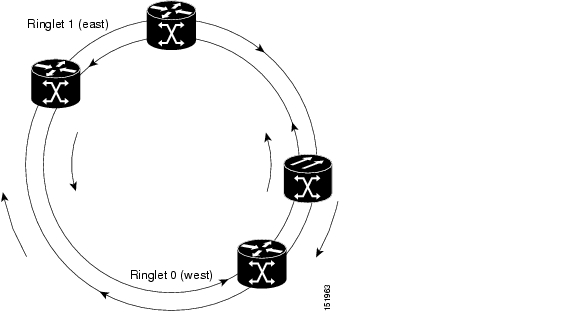
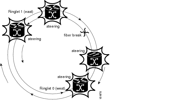
An RPR-IEEE is made up of dual counter-rotating rings (ringlets), one for clockwise or west data traffic and one for counter-clockwise or east data traffic. The ringlets are identified as Ringlet 0 and Ringlet 1 in Figure 26-1. The west ringlet traffic is transmitted out the west interface and received by the east interface. The east ringlet traffic is transmitted out the east interface and received by the west interface. Only east-to-west or west-to-east transmission schemes are allowed.
Figure 26-1 Dual-Ring Structure
RPR-IEEE Framing Process
The ML-Series card transports data around the RPR-IEEE through packet-over-SONET/SDH (POS) circuits. With POS, the RPR-IEEE frame is encapsulated into the SONET/SDH payload for transport over the SONET/SDH topology. For more information about POS, see Chapter 20, "POS on ONS Ethernet Cards."
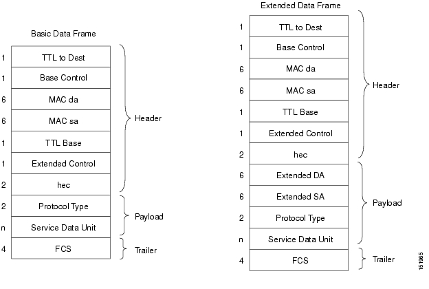
Figure 26-2 illustrates the IEEE 802.17 basic data frame for IP only networks and the expected IEEE 802.17b extended data frame used with bridging. The extended data frame adds an extended destination address and extended source address to the basic data frame.
Figure 26-2 RPR-IEEE Data Frames
Table 26-1 defines the most important fields in the RPR-IEEE data frame.
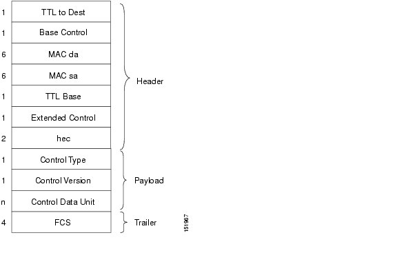
Figure 26-3 illustrates the RPR-IEEE topology and protection control frame. Topology and protection (TP) frames are usually sent to the broadcast address.
Figure 26-3 Topology and Protection Control Frame Formats
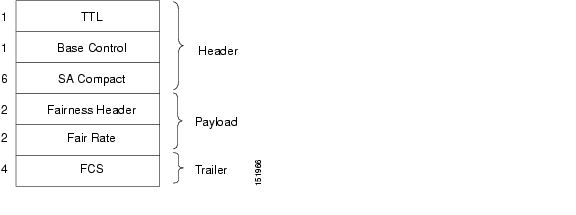
Figure 26-4 illustrates the RPR-IEEE fairness frame. Fairness frames are sent either to all stations or only the nearest neighbor depending on whether it is a single-choke fairness frame (SCFF) or multi-choke fairness frame (MCFF). Fairness frames are included in the total bandwidth of the QoS A0 service class. This eliminates the need for a destination address (DA). The MCFF type also includes an additional frequency division duplexing (FDD) frame to help smooth the fairness variation. The field SA Compact is the address of the station providing the fair rate.
Note
Figure 26-4 Fairness Frame Format
For comparison of RPR-IEEE frames and Cisco proprietary RPR frames, see the "Cisco Proprietary RPR Framing Process" section on page 17-5 for Cisco proprietary RPR framing information.
CTM and RPR-IEEE
Cisco Transport Manager (CTM) is an element management system (EMS) designed to integrate into an overall network management system (NMS) and interface with other higher level management tools. CTM supports RPR-IEEE provisioning on ML-Series cards. For more information, refer to the Cisco Transport Manager User Guide at:
http://www.cisco.com/en/US/products/sw/opticsw/ps2204/products_user_guide_list.html
Configuring RPR-IEEE Characteristics
Configuration tasks for RPR-IEEE characteristics are presented in the following sections:
•
–
–
–
•
–
–
–
–
–
•
–
–
–
Configuring the Attribute Discovery Timer
Because station attributes are communicated separately from topology and protection packets, there is a separate timer to control the frequency at which these packets are sent. Attribute propagation is therefore determined by the attribute discovery (ATD) timer. The default rate is one packet per second for each ringlet.
Note
To enable and configure the ATD, perform the following procedure, beginning in global configuration mode:
Configuring the Reporting of SONET Alarms
The ML-Series card reports SONET/SDH alarms through the CTC alarm panel in the same manner as other ONS cards. The ML-Series card can also report SONET/SDH alarms through the Cisco IOS command-line interface (CLI). Configuring CTC reporting does not affect Cisco IOS CLI reporting or vice-versa.
To configure the reporting of SONET/SDH alarms on the Cisco IOS CLI, perform the following procedure, beginning in global configuration mode:
Configuring BER Threshold Values
To configure BER threshold values for various alarms on an RPR-IEEE interface, refer to the "DLP-A533 Create Ethernet RMON Alarm Thresholds" task in the Cisco ONS 15454 Procedure Guide or to the "DLP-D441 Create Ethernet RMON Alarm Thresholds" task in the Cisco ONS 15454 SDH Procedure Guide.
Configuring RPR-IEEE Protection
RPR-IEEE has three protection states:
•
•
•
Figure 26-5 Each RPR-IEEE Node Responding to a Protection Event by Steering
You can modify many of the RPR-IEEE protection characteristics with the procedures in the following sections.
Configuring the Hold-off Timer
You can delay the protection response to a failure event, such as a signal failure or signal degradation, with the hold-off timer. Setting a longer timer can help avoid link errors that last long enough for detection, but do not last long enough to warrant the costs of protecting the span. This delay can result in higher traffic loss, however. The default value for this timer is 0 milliseconds.
To enable and configure the hold-off timer, perform the following procedure, beginning in global configuration mode:
Configuring Jumbo Frames
You can configure the interface to support jumbo frames. The jumbo setting specifies that the station support a maximum transfer unit (MTU) of up to 9100 bytes.
Caution
To enable and configure Jumbo frames, perform the following procedure, beginning in global configuration mode:
Configuring Forced or Manual Switching
You can request certain protection states to take effect manually on either span of the interface to avoid link usage or in anticipation of failures.
To enable and configure forced or manual switching, perform the following procedure, beginning in global configuration mode:
Configuring Protection Timers
Protection messages are sent based on the intervals of two timers. These timers apply under different circumstances:
•
•
The protection timers are configured the same on both spans of an interface.
To enable and configure the protection timers, perform the following procedure, beginning in global configuration mode:
Configuring the Wait-to-Restore Timer
When the failure is fixed, a wait-to-restore timer defines how long before the span reverts to its original state. This timer protects against false negatives in the detection of the failure status, which can avoid protection-flapping through the use of larger values. Smaller values result in faster recovery times, however. This timer can be configured between 0 and 1440 seconds, or configured to not recover automatically. The default for the timer is 10 seconds.
To enable and configure the wait-to-restore timer, perform the following procedure, beginning in global configuration mode:
Configuring a Span Shutdown
The rpr-ieee shutdown command performs the same task as the rpr-ieee protection request forced-switch command.
To cause a forced switch on the span of the interface, perform the following procedure, beginning in global configuration mode:
Configuring Keepalive Events
A station receives fairness messages from a link to determine its status. When the number of milliseconds that pass without receiving a fairness message from the neighboring stations exceeds a specified timer, a keepalive event is triggered. The keepalive event generates a protection event.
The timer can have a different value on each span and must be greater than or equal to the hold-off timer. This feature is independent of the fairness algorithm itself, but is still a function performed by the fairness machine.
To enable and configure the keepalives, perform the following procedure, beginning in global configuration mode:
Configuring Triggers for CRC Errors
You can configure a span shutdown when the ML-Series card receives CRC errors at a rate that exceeds the configured threshold and configured soak time.
To enable and configure the triggers for CRC errors, perform the following procedure, beginning in global configuration mode:
Configuring QoS on RPR-IEEE
802.17 RPR defines 3 service classes, each with unique QOS characteristics.
1.
2.
3.
With this different priorities of traffic can be configured with rate limiters and prescribed specific bandwidths. This configuration on each span might be identical (default) or might vary from the other span.
Class A
Class A is highest priority, lowest latency, and lowest jitter class . A has two types - A0 and A1. Can reserve a portion of the ringlet bandwidth using "reserve" keyword. This bandwidth is known as A0 bandwidth. The A0 bandwidth can only be used for classA traffic. Any Reserved bandwidth that is unused will remain unused on the ring, Reserved bandwidth is therefore expensive because it reduces the bandwidth available for best effort. This reservation is propagated throughout the ringlet, and all RPR stations recognize the bandwidth allocation cumulatively. Reserved A0 bandwidth can be used only by the station that reserves it. The default allocation is 0 Mbps. The unreserved classA bandwidth is called the A1 bandwidth. Service class A1 is configured as high-priority traffic in excess of the A0 bandwidth reservation, and can be rate-limited using the high tx-traffic rate limiter. The default allocation for A1 is 5 Mbps.
ClassB
This is the medium traffic priority. Lower priority than classA, but higher priority than classC. The medium transmit traffic rate limiter allows a certain amount of traffic to be added to the ringlet that is not subject to fairness eligibility, but must compete for the unreserved bandwidth with other traffic of the same service class. This traffic is committed information rate (B-CIR) traffic. The default allocation is 10 Mbps.ClassC
This is the lowest traffic priority. Class C cannot allocate any ring bandwidth guaranteesMQC -IEEE RPR CLI Characteristics
•
•
•
•
•
•
Configuring Traffic Rates for Transmission
To enable and configure the traffic rates, perform the following procedure, beginning in global configuration mode:
Configuring Fairness Weights
RPR-IEEE has a configurable fairness system, used to control congestion on each ringlet. This feature moderates bandwidth utilization of the ringlet to minimize and potentially eliminate starvation of any station. Each station has two instances of the fairness machine, to control traffic that is being transmitted and transited out of each span of the interface. Each fairness machine is devoted to a particular ringlet, and controls the traffic that is destined to that ringlet.
Each ringlet in an unwrapped ring is independent, and the fairness configuration can differ for each direction. The default is to configure both directions, but you can optionally specify east or west in the configuration.
The local station weight impacts how congested the station appears relative to other stations in the ringlet. It also affects how much more bandwidth a station can use. A higher weight gives the local station a greater share of the ringlet bandwidth. A lower weight decreases the bandwidth share of the local station. The default value is 0 configured as an exponent of 2, which yields an effective weight of 1.
To enable and configure the fairness weight, perform the following procedure, beginning in global configuration mode:
Configuring RPR-IEEE Service Classes Using the Modular QoS CLI
Traffic is directed to the three service classes supported by RPR-IEEE by using the standard Cisco Modular QoS CLI (MQC). MQC is a CLI structure that allows you to create traffic policies and attach these policies to interfaces. A traffic policy contains a traffic class and one or more QoS features. A traffic class classifies traffic, while the QoS features in the traffic policy determine how to treat the classified traffic.
For more information on general MQC configuration, refer to the following Cisco IOS documents:
•
•
Caution
Caution
To enable and configure the RPR-IEEE service classes with the MQC, perform the following procedure, beginning in global configuration mode:
Configuration Example for RPR-IEEE QoS
The following sample configurations are for RPR-IEEE QoS. Example 26-1 details a simple QoS configuration. Example 26-7 details a more complex configuration. The configuration on your network will differ based on your network design.
Configuration Example Using MQC to Configure Simple RPR-IEEE QoS
The following is an example of the configuration process for the three RPR-IEEE service classes:
Example 26-1 Configuration Example for a Simple RPR-IEEE QoS Configuration
class-map match-any DataHimatch cos 2 3 4class-map match-any Controlmatch cos 5 6 7policy-map EgrNNIclass Controlset rpr-ieee service-class aclass DataHiset rpr-ieee service-class bclass class-defaultset rpr-ieee service-class c!interface RPR-IEEE0no ip addressrpr-ieee protection pref jumborpr-ieee tx-traffic rate-limit high 100 eastrpr-ieee tx-traffic rate-limit high 100 westrpr-ieee tx-traffic rate-limit medium 200 eastrpr-ieee tx-traffic rate-limit medium 200 westservice-policy output EgrNNIConfiguration Example Using MQC to Configure Complex RPR-IEEE QoS
The following is an example of a more complex RPR-IEEE QoS configuration:
Example 26-2 Configuration Example for a Complex RPR-IEEE
class-map match-all classAmatch bridge-group 22!!policy-map EgrNNIclass classAset rpr-ieee service-class aclass class-defaultset rpr-ieee service-class c!bridge irb!!interface GigabitEthernet0no ip addressmode dot1q-tunnell2protocol-tunnel cdpl2protocol-tunnel stpl2protocol-tunnel vtpno cdp enablebridge-group 20bridge-group 20 spanning-disabled!interface GigabitEthernet1no ip addressmode dot1q-tunnell2protocol-tunnel cdpl2protocol-tunnel stpl2protocol-tunnel vtpno cdp enablebridge-group 22bridge-group 22 spanning-disabled!interface RPR-IEEE0ip address 1.1.1.3 255.255.255.0rpr-ieee fairness mode aggressiveservice-policy output EgrNNI!interface RPR-IEEE0.20encapsulation dot1Q 20no snmp trap link-statusbridge-group 20bridge-group 20 spanning-disabled!interface RPR-IEEE0.22encapsulation dot1Q 22no snmp trap link-statusbridge-group 22bridge-group 22 spanning-disabled!interface RPR-IEEE0.30encapsulation dot1Q 30no snmp trap link-statusbridge-group 30bridge-group 30 spanning-disabled!ip classlessVerifying and Monitoring RPR-IEEE
After RPR-IEEE is configured, you can use the following commands to verify setup and monitor its status:
•
–
–
–
–
•
–
–
–
–
•
–
–
–
–
•
–
–
–
–
–
–
–
Example 26-3 show interface rpr-ieee 0 Output
router# show interface rpr-ieee 0RPR-IEEE0 is up, line protocol is upHardware is RPR-IEEE Channelized SONET, address is 000e.8312.bcf0 (bia 000e.8312.bcf0)MTU 1500 bytes, BW 145152 Kbit, DLY 100 usec,reliability 255/255, txload 105/255, rxload 99/255Encapsulation: RPR-IEEE,West Span: loopback not setEast Span: loopback not setMAC passthrough not setRI: primary,active peer mac 000e.8312.b870ARP type: ARPA, ARP Timeout 04:00:00Last input 00:00:00, output never, output hang neverLast clearing of "show interface" counters neverInput queue: 0/75/0/0 (size/max/drops/flushes); Total output drops: 0Queueing strategy: fifoOutput queue: 0/40 (size/max)West Span: 5 minutes output rate 57872638 bits/sec, 25307 packets/sec5 minutes input rate 57786924 bits/sec, 25268 packets/secEast Span: 5 minutes output rate 2765315 bits/sec, 1197 packets/sec5 minutes input rate 0 bits/sec, 0 packets/sec26310890 packets input, 3230040117 bytesReceived 0 broadcasts (0 IP multicast)0 runts, 0 giants, 0 throttles3 input errors, 0 CRC, 0 frame, 0 overrun, 0 ignored0 watchdog, 0 multicast0 input packets with dribble condition detected32138811 packets output, 601868274 bytes, 0 underruns0 output errors, 0 collisions, 0 interface resets0 babbles, 0 late collision, 0 deferred0 lost carrier, 0 no carrier0 output buffer failures, 0 output buffers swapped outExample 26-4 show rpr-ieee fairness detail Output
router# show rpr-ieee fairness detailIEEE 802.17 Fairness on RPR-IEEE0:Bandwidth: 96768 kilobits per secondStation using aggressive rate adjustment.Westbound Tx (Ringlet 1)Weighted Fairness:Local Weight: 0 (1)Single-Choke Fairness Status:Local Congestion:Congested? NoHead? NoLocal Fair Rate:Approximate Bandwidth: 64892 Kbps25957 normalized bytes per aging interval51914 bytes per ageCoef aging intervalDownstream Congestion:Congested? NoTail? NoReceived Source Address: 0000.0000.0000Received Fair Rate:Approximate Bandwidth: FULL RATE65535 normalized bytes per aging intervalReserved Rate:0 Kbps0 bytes per aging intervalUnreserved Rate:96768 Kbps4838 bytes per aging intervalAllowed Rate:Approximate Bandwidth: 96000 Kbps4800 bytes per aging intervalAllowed Rate Congested:Approximate Bandwidth: 96000 Kbps4800 bytes per aging intervalTTL to Congestion: 255Total Hops Tx: 4Advertised Fair Rate:Approximate Bandwidth: FULL RATE65535 normalized bytes per aging interval8191 bytes per aging intervalEastbound Tx (Ringlet 0)Weighted Fairness:Local Weight: 0 (1)Single-Choke Fairness Status:Local Congestion:Congested? NoHead? NoLocal Fair Rate:Approximate Bandwidth: 0 Kbps0 normalized bytes per aging interval0 bytes per ageCoef aging intervalDownstream Congestion:Congested? NoTail? NoReceived Source Address: 0000.0000.0000Received Fair Rate:Approximate Bandwidth: FULL RATE65535 normalized bytes per aging intervalReserved Rate:0 Kbps0 bytes per aging intervalUnreserved Rate:96768 Kbps4838 bytes per aging intervalAllowed Rate:Approximate Bandwidth: 96000 Kbps4800 bytes per aging intervalAllowed Rate Congested:Approximate Bandwidth: 96000 Kbps4800 bytes per aging intervalTTL to Congestion: 255Total Hops Tx: 4Advertised Fair Rate:Approximate Bandwidth: FULL RATE65535 normalized bytes per aging interval8191 bytes per aging intervalExample 26-5 show rpr-ieee protection Output
router# show rpr-ieee protectionProtection Information for Interface RPR-IEEE0MAC AddressesWest Span (Ringlet 0 RX) neighbor 000b.fcff.9d34East Span (Ringlet 1 RX) neighbor 0013.1991.1fc0Station MAC address 0005.9a3c.59c0TP frame sending timers:fast timer: 10 msecslow timer: 1x100 msec (100 msec)Protection holdoff timers:L1 Holdoff Keepalive DetectionWest Span 0x10 msec ( 0 msec) West Span 5 msecEast Span 0x10 msec ( 0 msec) East Span 5 msecConfigured protection mode: STEERINGProtection StatusRing is IDLEProtection WTR period is 10 sec. (timer is inactive)Self Detected Requests Remote RequestsWest Span IDLE West Span IDLEEast Span IDLE East Span IDLEDistant RequestsEast Span IDLE West Span IDLEWest Span Failures: noneEast Span Failures: noneExample 26-6 show rpr-ieee topology detail Output
Note
router# show rpr-ieee topology detail802.17 Topology DisplayRX ringlet0->West span RX ringlet1->East spanNumber of nodes onringlet0: 5 ringlet1: 5=======================================================================Local Station Topology Info=======================================================================Topology entry:Station MAC address: 0005.9a3c.59c0West Span (Outer ringlet RX) neighbor 000b.fcff.9d34East Span (Inner ringlet RX) neighbor 0013.1991.1fc0Ring Topology: CLOSED (STABLE)Containment Active: NOA0 class reserved rate:ringlet0: 0 (mbps) ringlet1: 0 (mbps)Ringlet reserved rate:ringlet0: 0 (mbps) ringlet1: 0 (mbps)Ringlet unreserved rate:ringlet0: 96 (mbps) ringlet1: 96 (mbps)Ringlet effective unreserved rate:ringlet0: 95.9 (mbps) ringlet1: 95.9 (mbps)Advertised Protection requests:ringlet0: IDLE ringlet1: IDLEActive Edges:ringlet0: NO ringlet1: NOConfigured protection mode: STEERINGJumbo preference: NOT SET (ring doesn't support JUMBOS)Is revertive: YESMeasured LRTT: 0Sequence Number: 3ATD INFO:ATD timer: 1 secStation Name: ML100T-481A0 reserved Bandwidth:ringlet0: 0 mbps ringlet1: 0 mbpsSAS enabled: YESWeight:ringlet0: 1 ringlet1: 1Secondary Mac Addresses:MAC 1: 0000.0000.0000 (UNUSED)MAC 2: 0000.0000.0000 (UNUSED)=======================================================================Topology Map for Outer ringlet==============================================================================================================================================Topology entry at Index 1 on ringlet 0:Station MAC address: 000b.fcff.9d34Valid on ringlet0: YESEntry reachable: YESAdvertised Protection requests:ringlet0: IDLE ringlet1: IDLEActive Edges:ringlet0: NO ringlet1: NOPreferred protection mode: STEERINGJumbo preference: NOT SET (ring doesn't supports JUMBOS)Measured LRTT: 0Sequence Number: 3ATD INFO:Station Name: ML100X-491A0 reserved Bandwidth:ringlet0: 0 mbps ringlet1: 0 mbpsSAS enabled: YESWeight:ringlet0: 1 ringlet1: 1Secondary Mac Addresses:MAC 1: 0000.0000.0000 (UNUSED)MAC 2: 0000.0000.0000 (UNUSED)=======================================================================Topology entry at Index 2 on ringlet 0:Station MAC address: 0011.2130.b568Valid on ringlet0: YESEntry reachable: YESAdvertised Protection requests:ringlet0: IDLE ringlet1: IDLEActive Edges:ringlet0: NO ringlet1: NOPreferred protection mode: STEERINGJumbo preference: NOT SET (ring doesn't supports JUMBOS)Measured LRTT: 0Sequence Number: 3ATD INFO:Station Name: ML1000-491A0 reserved Bandwidth:ringlet0: 0 mbps ringlet1: 0 mbpsSAS enabled: YESWeight:ringlet0: 1 ringlet1: 1Secondary Mac Addresses:MAC 1: 0000.0000.0000 (UNUSED)MAC 2: 0000.0000.0000 (UNUSED)=======================================================================Topology entry at Index 3 on ringlet 0:Station MAC address: 0005.9a39.7630Valid on ringlet0: YESEntry reachable: YESAdvertised Protection requests:ringlet0: IDLE ringlet1: IDLEActive Edges:ringlet0: NO ringlet1: NOPreferred protection mode: STEERINGJumbo preference: NOT SET (ring doesn't supports JUMBOS)Measured LRTT: 0Sequence Number: 3ATD INFO:Station Name: ML1000-492A0 reserved Bandwidth:ringlet0: 0 mbps ringlet1: 0 mbpsSAS enabled: YESWeight:ringlet0: 1 ringlet1: 1Secondary Mac Addresses:MAC 1: 0000.0000.0000 (UNUSED)MAC 2: 0000.0000.0000 (UNUSED)=======================================================================Topology entry at Index 4 on ringlet 0:Station MAC address: 0013.1991.1fc0Valid on ringlet0: YESEntry reachable: YESAdvertised Protection requests:ringlet0: IDLE ringlet1: IDLEActive Edges:ringlet0: NO ringlet1: NOPreferred protection mode: STEERINGJumbo preference: NOT SET (ring doesn't supports JUMBOS)Measured LRTT: 0Sequence Number: 3ATD INFO:Station Name: ML100T-482A0 reserved Bandwidth:ringlet0: 0 mbps ringlet1: 0 mbpsSAS enabled: YESWeight:ringlet0: 1 ringlet1: 1Secondary Mac Addresses:MAC 1: 0000.0000.0000 (UNUSED)MAC 2: 0000.0000.0000 (UNUSED)=======================================================================Topology entry at Index 5 on ringlet 0:Station MAC address: 0005.9a3c.59c0Valid on ringlet0: YESEntry reachable: YESAdvertised Protection requests:ringlet0: IDLE ringlet1: IDLEActive Edges:ringlet0: NO ringlet1: NOPreferred protection mode: STEERINGJumbo preference: NOT SET (ring doesn't supports JUMBOS)Measured LRTT: 0Sequence Number: 3ATD INFO:Station Name: ML100T-481A0 reserved Bandwidth:ringlet0: 0 mbps ringlet1: 0 mbpsSAS enabled: YESWeight:ringlet0: 1 ringlet1: 1Secondary Mac Addresses:MAC 1: 0000.0000.0000 (UNUSED)MAC 2: 0000.0000.0000 (UNUSED)=======================================================================Topology Map for Inner ringlet==============================================================================================================================================Topology entry at Index 1 on ringlet 1:Station MAC address: 0013.1991.1fc0Valid on ringlet1: YESEntry reachable: YESAdvertised Protection requests:ringlet0: IDLE ringlet1: IDLEActive Edges:ringlet0: NO ringlet1: NOPreferred protection mode: STEERINGJumbo preference: NOT SET (ring doesn't supports JUMBOS)Measured LRTT: 0Sequence Number: 3ATD INFO:Station Name: ML100T-482A0 reserved Bandwidth:ringlet0: 0 mbps ringlet1: 0 mbpsSAS enabled: YESWeight:ringlet0: 1 ringlet1: 1Secondary Mac Addresses:MAC 1: 0000.0000.0000 (UNUSED)MAC 2: 0000.0000.0000 (UNUSED)=======================================================================Topology entry at Index 2 on ringlet 1:Station MAC address: 0005.9a39.7630Valid on ringlet1: YESEntry reachable: YESAdvertised Protection requests:ringlet0: IDLE ringlet1: IDLEActive Edges:ringlet0: NO ringlet1: NOPreferred protection mode: STEERINGJumbo preference: NOT SET (ring doesn't supports JUMBOS)Measured LRTT: 0Sequence Number: 3ATD INFO:Station Name: ML1000-492A0 reserved Bandwidth:ringlet0: 0 mbps ringlet1: 0 mbpsSAS enabled: YESWeight:ringlet0: 1 ringlet1: 1Secondary Mac Addresses:MAC 1: 0000.0000.0000 (UNUSED)MAC 2: 0000.0000.0000 (UNUSED)=======================================================================Topology entry at Index 3 on ringlet 1:Station MAC address: 0011.2130.b568Valid on ringlet1: YESEntry reachable: YESAdvertised Protection requests:ringlet0: IDLE ringlet1: IDLEActive Edges:ringlet0: NO ringlet1: NOPreferred protection mode: STEERINGJumbo preference: NOT SET (ring doesn't supports JUMBOS)Measured LRTT: 0Sequence Number: 3ATD INFO:Station Name: ML1000-491A0 reserved Bandwidth:ringlet0: 0 mbps ringlet1: 0 mbpsSAS enabled: YESWeight:ringlet0: 1 ringlet1: 1Secondary Mac Addresses:MAC 1: 0000.0000.0000 (UNUSED)MAC 2: 0000.0000.0000 (UNUSED)=======================================================================Topology entry at Index 4 on ringlet 1:Station MAC address: 000b.fcff.9d34Valid on ringlet1: YESEntry reachable: YESAdvertised Protection requests:ringlet0: IDLE ringlet1: IDLEActive Edges:ringlet0: NO ringlet1: NOPreferred protection mode: STEERINGJumbo preference: NOT SET (ring doesn't supports JUMBOS)Measured LRTT: 0Sequence Number: 3ATD INFO:Station Name: ML100X-491A0 reserved Bandwidth:ringlet0: 0 mbps ringlet1: 0 mbpsSAS enabled: YESWeight:ringlet0: 1 ringlet1: 1Secondary Mac Addresses:MAC 1: 0000.0000.0000 (UNUSED)MAC 2: 0000.0000.0000 (UNUSED)=======================================================================Topology entry at Index 5 on ringlet 1:Station MAC address: 0005.9a3c.59c0Valid on ringlet1: YESEntry reachable: YESAdvertised Protection requests:ringlet0: IDLE ringlet1: IDLEActive Edges:ringlet0: NO ringlet1: NOPreferred protection mode: STEERINGJumbo preference: NOT SET (ring doesn't supports JUMBOS)Measured LRTT: 0Sequence Number: 3ATD INFO:Station Name: ML100T-481A0 reserved Bandwidth:ringlet0: 0 mbps ringlet1: 0 mbpsSAS enabled: YESWeight:ringlet0: 1 ringlet1: 1Secondary Mac Addresses:MAC 1: 0000.0000.0000 (UNUSED)MAC 2: 0000.0000.0000 (UNUSED)Configuring RPR-IEEE End-to-End
You need to use both CTC and Cisco IOS to configure RPR-IEEE for the ML-Series card. CTC is the graphical user interface (GUI) that serves as the enhanced craft tool for specific ONS node operations, including the provisioning of the point-to-point SONET/SDH circuits required for RPR-IEEE. Cisco IOS is used to configure RPR-IEEE on the ML-Series card and its interfaces.
Successfully creating an RPR-IEEE requires these procedures:
•
•
•
•
Caution
Note
Provisioning Card Mode
The first task in creating an end-to-end RPR-IEEE is to set the CTC card mode to 802.17. For more information on this task, see the "Provisioning Card Mode" section on page 2-4.
Connecting the ML-Series Cards with Point-to-Point STS/STM Circuits
You connect the ML-Series cards in an RPR-IEEE through point-to-point STS/STM circuits. These circuits use the ONS 15454 SONET/SDH network and are provisioned using CTC in the same general manner as provisioning ONS 15454 SONET/SDH optical circuits. After putting the ML-Series card in RPR-IEEE mode and creating the circuits through CTC, further provisioning of the ML-Series card is done through the Cisco IOS CLI. It is assumed that the SONET/SDH node and its network are already active.
Guidelines for Connecting the ML-Series Cards with Point-to-Point STS/STM Circuits
These are some general guidelines for configuring the circuits required by RPR-IEEE:
•
•
Detailed CTC circuit procedures are available in the NTP-A343, "Create an Automatically Routed OC-N Circuit," and the NTP-A344, "Create a Manually Routed OC-N Circuit," procedures in the "Create Circuits and VT Tunnels" chapter of the Cisco ONS 15454 Procedure Guide and in the NTP-D323, "Create an Automatically Routed High-Order Circuit," and NTP-D 324, "Create a Manually Routed High-Order Circuit," procedures in the "Create Circuits and Tunnels" chapter of the Cisco ONS 15454 SDH Procedure Guide.
Example of Connecting the ML-Series Cards with Point-to-Point STS/STM Circuits
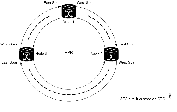
The three-node RPR-IEEE in Figure 26-6 shows an example of the point-to-point circuits needed.
Figure 26-6 Three Node RPR-IEEE Example
To configure the circuits for the example, you would need to perform these tasks in CTC:
1.
2.
3.
Creating the RPR-IEEE Interface and Bridge Group
The plug-n-play feature of RPR-IEEE automatically discovers topology and advertises station capabilities. This allows ML-Series cards to become operational without manual intervention when the ML-Series card is in 802.17 mode and the SONET/SDH circuits are configured. Unlike Cisco proprietary RPR, RPR-IEEE does not require the user to configure POS interfaces.
The additional Cisco IOS CLI provisioning needed to set up basic, functional RPR is straightforward. The user needs to complete these tasks:
1.
2.
3.
4.
5.
6.
7.
8.
Caution
Understanding the RPR-IEEE Interface
When the card mode is changed to IEEE 802.17, the physical rpr-ieee interface is automatically created. It provides all the normal attributes of a Cisco IOS virtual interface, such as support for default routes.
An rpr-ieee interface is considered a trunk port, and like all trunk ports, subinterfaces must be configured for the rpr-ieee interface to join a bridge group.
The POS interfaces are not visible or configurable in 802.17 card mode.
Understanding the RPR-IEEE Bridge Group
The default behavior of the ML-Series card is that no traffic is bridged over the RPR-IEEE even with the interfaces enabled. This is in contrast to many Layer 2 switches, including the Cisco Catalyst 6500 series and the Cisco Catalyst 7600 series, which forward VLAN 1 by default. The ML-Series card will not forward any traffic by default, including untagged or VLAN 1 tagged packets.
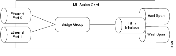
For any RPR-IEEE traffic to be bridged on an ML-Series card, a bridge group needs to be created for that traffic. Bridge groups maintain the bridging and forwarding between the interfaces on the ML-Series card and are locally significant. Interfaces not participating in a bridge group cannot forward bridged traffic. The bridge group enables data transport across the RPR-IEEE infrastructure.
Figure 26-7 illustrates a bridge group spanning the ML-Series card interfaces, including the rpr-ieee virtual interface.
Figure 26-7 RPR-IEEE Bridge Group
Caution
Caution
To enable the rpr-ieee interface and create the bridge group, perform the following procedure, beginning in global configuration mode:
Configuration Examples for Cisco IOS CLI Portion of End-to-End RPR-IEEE
The following examples show RPR-IEEE configurations. Example 26-7 is a simple configuration. It does the minimum needed to bridge the ML-Series card's Ethernet ports and the ML-Series card's RPR-IEEE and leaves the RPR-IEEE characteristics at default. Example 26-8 is a complex example of RPR-IEEE with multiple bridge groups, configured characteristics, and QoS.
Example 26-7 Configuration Example for Simple RPR-IEEE
version 12.2no service padservice timestamps debug datetime msec localtimeservice timestamps log datetime msec localtimeno service password-encryptionservice internal!hostname ml!boot-start-markerboot-end-marker!enable password x!clock timezone PST -8clock summer-time PDT date Apr 2 2006 2:00 Oct 29 2006 2:00ip subnet-zerono ip routingno ip domain-lookup!no mpls traffic-eng auto-bw timers frequency 0!bridge irb!!interface GigabitEthernet0no ip addressno ip route-cacheno ip mroute-cachebridge-group 10bridge-group 10 spanning-disabled!interface GigabitEthernet1no ip addressno ip route-cacheno ip mroute-cacheshutdown!interface RPR-IEEE0no ip addressno ip route-cacherpr-ieee fairness mode aggressive!interface RPR-IEEE0.10encapsulation dot1Q 10no ip route-cacheno snmp trap link-statusbridge-group 10bridge-group 10 spanning-disabled!ip classlessno ip http serverExample 26-8 Configuration Example for a Complex RPR-IEEE
version 12.2no service padservice timestamps debug datetime msec localtimeservice timestamps log datetime msec localtimeno service password-encryptionservice internal!hostname ml!boot-start-markerboot-end-marker!enable password x!clock timezone PST -8clock summer-time PDT date Apr 2 2006 2:00 Oct 29 2006 2:00ip subnet-zerono ip domain-lookup!vlan dot1q tagno mpls traffic-eng auto-bw timers frequency 0!bridge irb!!interface GigabitEthernet0no ip addressbridge-group 12bridge-group 12 spanning-disabled!interface GigabitEthernet1no ip addressmode dot1q-tunnelbridge-group 22bridge-group 22 spanning-disabled!interface RPR-IEEE0ip address 11.1.1.1 255.255.255.0trigger crc-error threshold 4 easttrigger crc-error threshold 4 westtrigger crc-error action easttrigger crc-error action westtrigger crc-error delay 3 easttrigger crc-error delay 3 wrpr-ieee atd-timer 10rpr-ieee protection wtr-timer 60!interface RPR-IEEE0.1encapsulation dot1Q 1 nativeip address 10.1.1.4 255.255.255.0no snmp trap link-status!interface RPR-IEEE0.10encapsulation dot1Q 10no snmp trap link-statusbridge-group 10bridge-group 10 spanning-disabled!interface RPR-IEEE0.12encapsulation dot1Q 12ip address 1.1.1.12 255.255.255.0no snmp trap link-statusbridge-group 12bridge-group 12 spanning-disabled!interface RPR-IEEE0.22encapsulation dot1Q 22no snmp trapbridge-group 22bridge-group 22 spanning-disabled!interface RPR-IEEE0.800encapsulation dot1Q 800ip address 8.1.1.1 255.255.255.224no snmp trap link-status!ip classlessno ip http server!!snmp-server community public RWsnmp-server ifindex persistsnmp-server trap link ietfsnmp-server host 64.101.18.178 version 2c publicsnmp-server host 64.101.18.193 version 2c public!!control-plane!line con 0exec-timeout 0 0line vty 0 4exec-timeout 0 0no loginendVerifying RPR-IEEE End-to-End Ethernet Connectivity
After successfully completing the procedures to provision an RPR-IEEE, you can test Ethernet connectivity between the Ethernet access ports on the separate ML-Series cards. To do this, use your standard Ethernet connectivity testing.
Understanding Redundant Interconnect
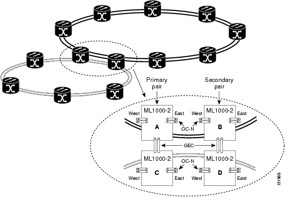
Ring interconnect (RI) is a mechanism to interconnect RPRs, both RPR-IEEE and Cisco proprietary RPR, for protection from failure. It does this through redundant pairs of back-to-back Gigabit Ethernet connections that bridge RPR networks. One connection is the active node and the other is the standby node. During a failure of the active node, link, or card, the detection of the failure triggers a switchover to the standby node. Figure 26-8 illustrates an example of RPR RI.
Figure 26-8 RPR RI
Characteristics of RI on the ML-Series Card
RI on the ML-Series card has these characteristics:
•
•
•
•
–
–
–
•
Caution
Caution
Caution
Caution
RI Configuration Example
Excerpts of sample Cisco IOS code for an RPR RI for ML-Series-card-only connections are provided in Example 26-9 and Example 26-10. Excerpts of sample Cisco IOS code for an RPR RI where the primary and secondary ML-Series cards are connected to a foreign switch, any switch that is not an ML-Series card, are provided in Example 26-9 and Example 26-10. Status of RI can be found as illustratedin Example 26-13.
Example 26-9 Primary ML-Series Card Configuration
interface rpr-ieee0no ip addressrpr-ieee ri modeno shutdown
In the above example, after rpr-ieee ri mode you need to insert the MAC address of the primary peer. To fetch this address, log in to the primary peer ML-Series card and enter the command show interface rpr-ieee as follows:
Router#show interface rpr-ieee 0RPR-IEEE0 is up, line protocol is upHardware is RPR-IEEE Channelized SONET, address is 0019.076c.7f71 (bia 0019.076c.7f71)
The MAC address of the primary peer is 0019.076c.7f71. The configuration would now appear as rpr-ieee ri mode 0019.076c.7f71.
Example 26-10 Secondary ML-Series Card Configuration
interface rpr-ieee0no ip addressrpr-ieee ri modeno shutdown
In the above example, after rpr-ieee ri mode you need to insert the MAC address of the secondary peer. To fetch this address, log in to the secondary peer ML-Series card and enter the command show interface rpr-ieee as follows:
Router#show interface rpr-ieee 0RPR-IEEE0 is up, line protocol is upHardware is RPR-IEEE Channelized SONET, address is 0019.076c.7f72 (bia 0019.076c.7f72)
The MAC address of the secondary peer is 0019.076c.7f72. The configuration would now appear as rpr-ieee ri mode 0019.076c.7f72.
Example 26-11 Primary ML-Series Card Configuration with Connection to Switch
interface rpr-ieee0no ip addressrpr-ieee ri moderpr-ieee ri foreignno shutdown
In the above example, after rpr-ieee ri mode you need to insert the MAC address of the primary peer. To fetch this address, log in to the primary peer ML-Series card and enter the command show interface rpr-ieee as follows:
Router#show interface rpr-ieee 0RPR-IEEE0 is up, line protocol is upHardware is RPR-IEEE Channelized SONET, address is 0019.076c.7f73 (bia 0019.076c.7f73)
The MAC address of the primary peer is 0019.076c.7f73. The configuration would now appear as rpr-ieee ri mode 0019.076c.7f73.
Example 26-12 Secondary ML-Series Card Configuration with Connection to Switch
interface rpr-ieee0no ip addressrpr-ieee ri moderpr-ieee ri foreignno shutdown
In the above example, after rpr-ieee ri mode you need to insert the MAC address of the secondary peer. To fetch this address, log in to the secondary peer ML-Series card and enter the command show interface rpr-ieee as follows:
Router#show interface rpr-ieee 0RPR-IEEE0 is up, line protocol is upHardware is RPR-IEEE Channelized SONET, address is 0019.076c.7f74 (bia 0019.076c.7f74)
The MAC address of the secondary peer is 0019.076c.7f74. The configuration would now appear as rpr-ieee ri mode 0019.076c.7f74.
Note
Example 26-13 Status of Redundant Interconnect can be found using
Router#sh ons dot17 riRedundant Interconnect DataMode: primaryState: standbyPeer: 0000.1111.2222Peer Active: falseSpans Provisioned : trueTopology: stableRing if: upInterconnect if: downSecondary IC mode: link-up, WTR-timer:60 Adjusted:65Ucode mode: StandbyInterconnect interface 0:name: GigabitEthernet0state: not upmember port channel: falseInterconnect interface 1:name: GigabitEthernet1state: not upmember port channel: falseMonitored if: interconnect
![]()
![]()
![]()
![]()
![]()
![]()
![]()
![]()
Posted: Thu Nov 8 00:50:13 PST 2007
All contents are Copyright © 1992--2007 Cisco Systems, Inc. All rights reserved.
Important Notices and Privacy Statement.