|
|

Table Of Contents
3.1.8 DWDM and TDM Hybrid Node Configurations
3.1.9 Transponder (Client) Shelf Layout
3.1.10 Inter-Shelf Communications
Node Configurations
This chapter describes the various configurations supported by DWDM applications in the Cisco ONS 15454.
The following topics are covered in this chapter:
3.1 Node Configurations
The ONS 15454 supports the following DWDM node configurations in the C-band:
•
ROADM
•
•
•
•
•
•
The ONS 15454 supports the following DWDM node configurations in the L-band:
•
•
•
•
•
Note
3.1.1 ROADM Node
The following sections describe the C-band and L-band ROADM nodes.
3.1.1.1 C-Band ROADM Node
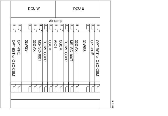
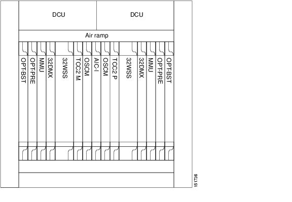
A ROADM node can add and drop wavelengths without changing the physical fiber connections. ROADM nodes consist of two 32WSS cards. 32DMX or 32DMX-O demultiplexers are typically installed, but are not required. If amplification is not used, you can install TXPs and MXPs in any open slot. Figure 3-1 shows an example of an amplified ROADM node configuration.
Figure 3-1 ROADM Node with OPT-PRE, OPT-BST, 32WSS, and 32DMX Cards Installed
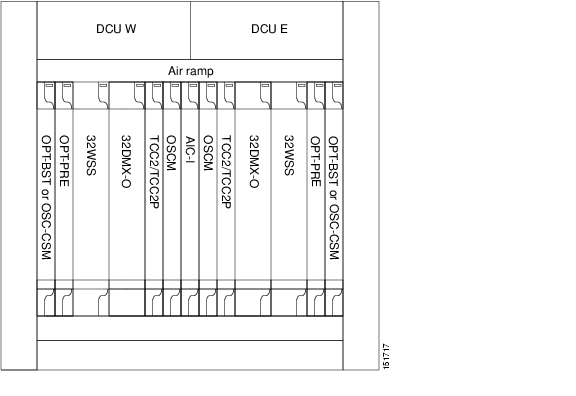
If the ROADM node receives a tilted optical signal, you can replace the single-slot 32DMX card with the double-slot 32DMX-O card to equalize the signal at the optical channel layer instead of the transport section layer. However, if 32DMX-O cards are installed, you cannot use Slots 6 and 12 for TXP or MXP cards.
Figure 3-2 shows an example of a ROADM node with 32DMX-O cards installed.
Figure 3-2 ROADM Node with OPT-PRE, OPT-BST, 32WSS, and 32DMX-O Cards Installed
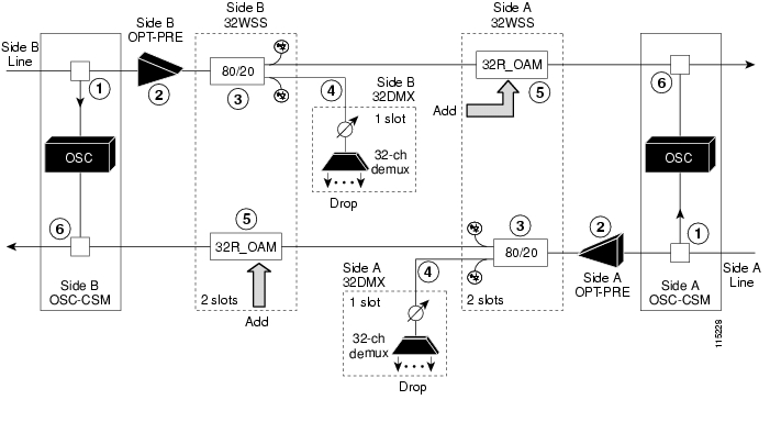
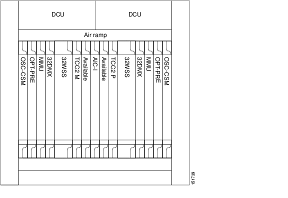
Figure 3-3 shows an example of a reconfigurable OADM east-to-west optical signal flow. The west-to-east optical signal flow follows an identical path through the west OSC-CSM and west 32WSS cards. In this example, OSC-CSM cards are installed, so OPT-BST cards are not needed.
Figure 3-3 ROADM Node with OPT-PRE, OPT-BST, 32WSS, and 32DMX-O Cards Installed
3.1.1.2 C-Band ROADM Node with MMU
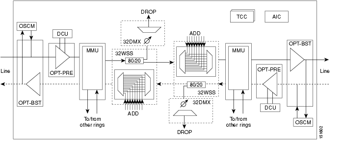
Figure 3-4 is an example of a multi-ring/mesh node layout.
Figure 3-4 Multiring/Mesh C-Band Node
The OPT-PRE card amplifies the aggregate signal coming from the west line and the MMU card splits the signal to route the channels to other rings. The signal out of the MMU EXP port is then split by the west 32WSS card and sent to the 32DMX and the east 32WSS cards. This process multiplexes, equalizes, and transmits the relevant express channels and the added channel towards the east.
The multiplexed signal is then fed into the MMU card, which combines the channels with the new channel coming from other rings. The channel is then sent to the OPT-BST card, which amplifies the aggregated channels and combines the OSC. The resulting signal is launched into the east transmission fiber.
The transmit path for the other direction follows an identical path through the west 32WSS and the west OPT-BST card. The signal from the east fiber enters the east OPT-BST card, where the OSC signal is terminated. The aggregated DWDM signal is then fed into the east OPT-PRE card.
In the east OPT-PRE card, MAL performs the last chromatic dispersion compensation and then sends the signal to the MMU card, which splits the signal into two different paths. One of the signal paths is directly connected to the east 32WSS card, where the signal is split according to an 80/20 ratio. The other signal path is to the MMU EXP A port for future interconnection with other rings.
The Drop component from the east 32WSS enters the east 32DMX card, is attenuated by the VOA operating at the OTS layer, and is demultiplexed at the OCH layer.
The Express component enters the west 32WSS card's OTS Rx port, is demultiplexed at the OCH layer, and stops or passes through according to the optical switch state.
The channels enter the west MMU and combine with the signals coming from the other rings. The OPT-BST card amplifies these signals and launches them into the west fiber.
All the cards that are used to build a multiring or mesh C-band node can be plugged into a single ONS 15454 shelf and a DCU shelf can be implemented if dispersion compensation is necessary.
Figure 3-5 shows a typical node configuration. The positions of the cards housed in Slots 1 through 6 and 12 through 17 are not mandatory. They can be swapped without any problem, but the common control cards have reserved slots in the middle of the shelf. You can equip TXP or MXP cards in configurations without preamplification, and you can install an OSC-CSM card in Slot 1 and 17 in configurations without booster amplification. You may leave Slot 8 and 10 empty in configurations without booster amplification.
Figure 3-5 Multiring/Mesh C-Band Shelf Layout
3.1.1.3 L-Band ROADM Node
A ROADM node adds and drops wavelengths without changing the physical fiber connections. Figure 3-6 shows an example of an amplified ROADM node configuration.
Figure 3-6 L-Band ROADM Node
ROADM nodes are equipped with two 32WSS-L cards. 32DMX-L cards are typically installed, but are not required. You can install TXPs and MXPs in Slots 6 and 12 and, if amplification is not used, in any open slot.
3.1.2 Line Amplifier Node
The following sections describe the various C-band and L-band amplifier nodes that are available.
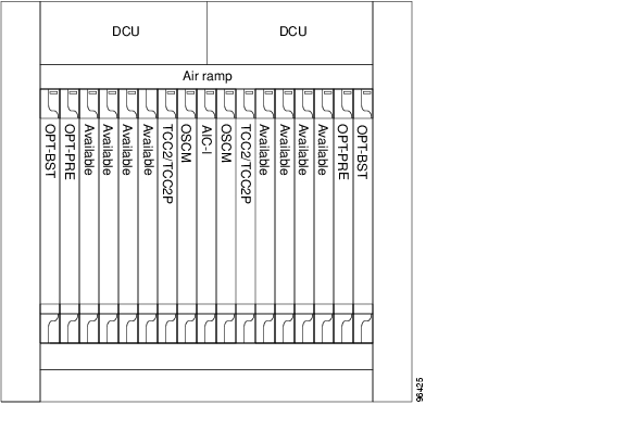
3.1.2.1 C-Band Line Amplifier Node with Booster and Preamplifier
A line node is a single ONS 15454 node equipped with OPT-PRE amplifiers and OPT-BST amplifiers, two OSCM or OSC-CSM cards, and TCC2/TCC2P cards. Attenuators might also be required between each preamplifier and booster amplifier to match the optical input power value and to maintain the amplifier gain tilt value. Two OSCM or OSC-CSM cards are connected to the east or west ports of the booster amplifiers to multiplex the OSC signal with the pass-through channels.
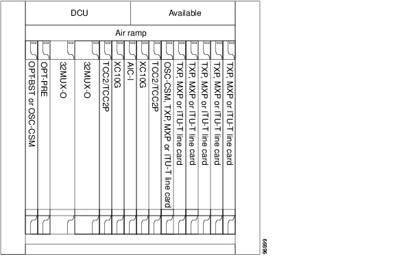
Figure 3-7 shows an example of a line node configuration.
Figure 3-7 Line Node Configuration with Booster and Preamplifier
3.1.2.2 C-Band Line Amplifier Node with Preamplifier Only
A C-band line amplifier node contains a single ONS 15454 shelf equipped with two OPT-PRE or OPT-BST amplifiers, two OSCM or OSC-CSM cards, and two TCC2/TCC2P cards. If the node consists of two booster amplifiers only, the two OSCM cards are connected to the OSC ports of the booster amplifier to multiplex the OSC signal with the pass-through channels.
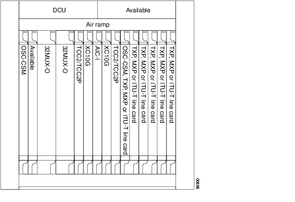
Figure 3-8 shows an example of a line node configuration.
Figure 3-8 Line Node Configuration with Preamplifier
3.1.2.3 L-Band Line Amplifier Node
An L-band line amplifier node contains a single ONS 15454 shelf equipped with two OPT-AMP-L amplifiers or OPT-BST-L amplifiers, two OSCM or OSC-CSM cards, and two TCC2/TCC2P cards.
Two OSCM or OSC-CSM cards are connected to the OSC ports of the booster amplifiers to multiplex the OSC signal with the pass-through channels.
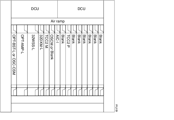
Figure 3-9 shows an example of a line node configuration.
Figure 3-9 Line Node Configuration with Amplifier
3.1.3 OSC Regeneration Node
An OSC regeneration node is added to DWDM networks for two reasons:
•
•
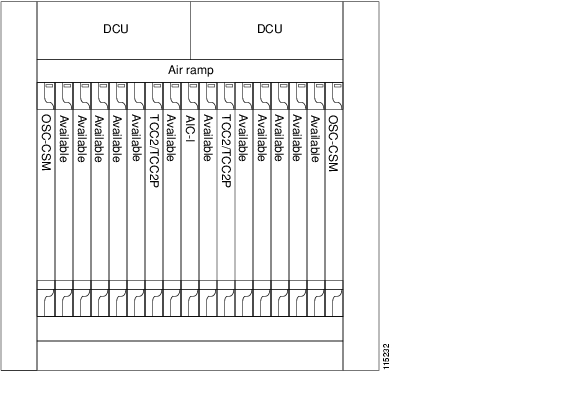
OSC regeneration nodes require two OSC-CSM cards, as shown in Figure 3-10.
Figure 3-10 OSC Regeneration Line Node Configuration
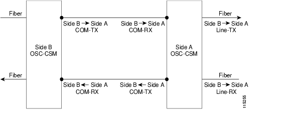
Figure 3-11 shows the OSC regeneration node OSC signal flow.
Figure 3-11 OSC Regeneration Line Site Example
3.1.4 C-Band OADM Node
An OADM node is a single ONS 15454 node equipped with at least one AD-xC-xx.x card or one AD-xB-xx.x card and two TCC2/TCC2P cards. The 32MUX-O or 32DMX-O cards cannot be provisioned. In an OADM node, channels can be added or dropped independently from each direction, passed through the reflected bands of all OADMs in the DWDM node (called express path), or passed through one OADM card to another OADM card without using a time-division multiplexing (TDM) ITU line card (called optical pass-through) if an external patchcord is installed.
Unlike express path, an optical pass-through channel can be converted later to an add/drop channel in an altered ring without affecting another channel. OADM amplifier placement and required card placement is determined by the Cisco MetroPlanner tool or your site plan.
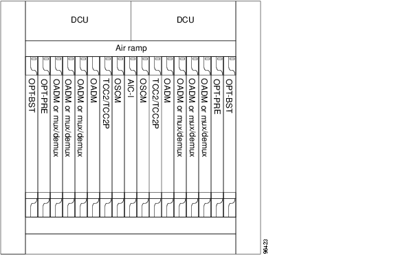
There are different categories of OADM nodes, such as amplified, passive, and anti-ASE. For anti-ASE node information, see "C-Band Anti-ASE Node" section. Figure 3-12 shows an example of an amplified OADM node configuration.
Figure 3-12 OADM Node Configuration
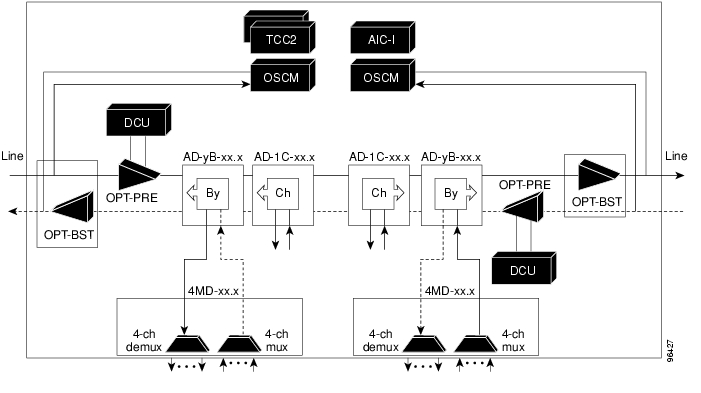
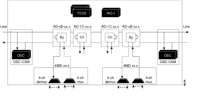
Figure 3-13 shows an example of the channel flow on the amplified OADM node. Because the 32 wavelength plan is based on eight bands (each band contains four channels), optical adding and dropping can be performed at the band level and/or at the channel level (meaning individual channels can be dropped).
Figure 3-13 Amplified OADM Node Channel Flow
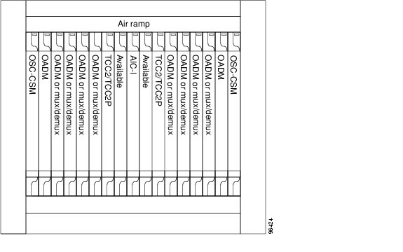
Figure 3-14 shows an example of a passive OADM node configuration. The passive OADM node is equipped with a band filter, one four-channel multiplexer/demultiplexer, and a channel filter on each side of the node.
Figure 3-14 Passive OADM Node Configuration
Figure 3-15 shows an example of traffic flow on the passive OADM node. The signal flow of the channels is the same as that described in Figure 3-13 except that the OSC-CSM card is being used instead of the OPT-BST amplifier and the OSCM card.
Figure 3-15 Passive OADM Node Channel Flow
3.1.5 C-Band Anti-ASE Node
In a meshed ring network, the ONS 15454 requires a node configuration that prevents ASE accumulation and lasing. An anti-ASE node can be created by configuring a hub node or an OADM node with some modifications. No channels can travel through the express path, but they can be demultiplexed and dropped at the channel level on one side and added and multiplexed on the other side.
The hub node is the preferred node configuration when some channels are connected in pass-through mode. For rings that require a limited number of channels, combine AD-xB-xx.x and 4MD-xx.x cards, or cascade AD-xC-xx.x cards.
Figure 3-16 shows an example of traffic flow on an anti-ASE node that uses all wavelengths in the pass-through mode. Use Cisco MetroPlanner or another network planning tool to determine the best configuration for anti-ASE nodes.
Figure 3-16 Anti-ASE Node Channel Flow
3.1.6 Hub Node
This section describes C-band and L-band hub nodes.
3.1.6.1 C-Band Hub Node
A hub node is a single ONS 15454 node equipped with two TCC2/TCC2P cards, two OSCM or OSC-CSM cards, up to two OPT-BST or OPT-BST-E cards, up to two OPT-PRE cards, and one of the following combinations:
•
•
Note
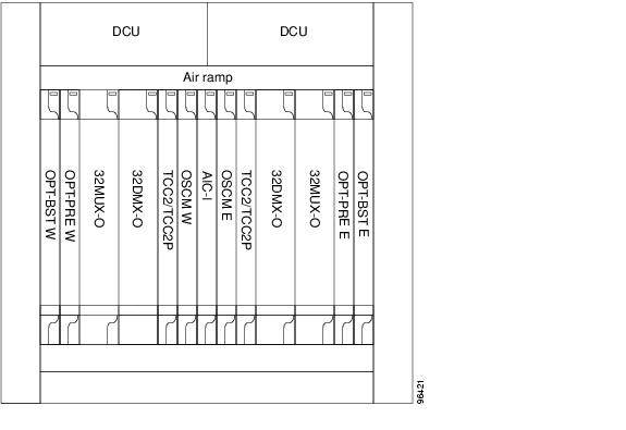
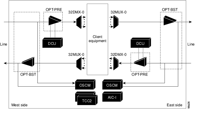
A DCU can also be added, if necessary. The hub node does not support both DWDM and TDM applications since the DWDM slot requirements do not leave room for TDM cards. Figure 3-17 shows a hub node configuration with the 32MUX-O and 32DMX-O cards installed.
Note
Figure 3-17 C-Band Hub Node Configuration
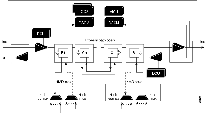
Figure 3-18 shows the channel flow for a hub node. Up to 32 channels from the client ports are multiplexed and equalized onto one fiber using the 32MUX-O card. Then, multiplexed channels are transmitted on the line in the eastward direction and fed to the OPT-BST amplifier. The output of this amplifier is combined with an output signal from the OSCM card, and transmitted toward the east line.
Received signals from the east line port are split between the OSCM card and an OPT-PRE amplifier. Dispersion compensation is applied to the signal received by the OPT-PRE amplifier, and it is then sent to the 32DMX-O card, which demultiplexes and attenuates the input signal. The west receive fiber path is identical through the west OPT-BST amplifier, the west OPT-PRE amplifier, and the west 32DMX-O card.
Figure 3-18 Hub Node Channel Flow
3.1.6.2 L-Band Hub Node
An L-band hub node is a single ONS 15454 node equipped with two TCC2/TCC2P cards, two OSCM or OSC-CSM cards, up to two OPT-BST-L cards, up to two OPT-PRE cards, two 32WSS-L cards, and two 32DMX-L cards.
Note
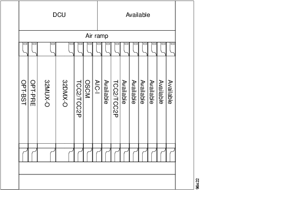
A DCU can also be added, if necessary. The hub node does not support both DWDM and TDM applications since the DWDM slot requirements do not leave room for TDM cards. Figure 3-19 shows a hub node configuration.
Figure 3-19 L-Band Hub Node
3.1.7 Terminal Node
This section explains the following nodes:
•
•
•
3.1.7.1 C-Band Terminal Node
A terminal node is a single ONS 15454 node equipped with two TCC2/TCC2P cards, an OSCM or OSC-CSM card, an OPT-BST or OPT-BST-E card, an OPT-PRE card, and one of the following combinations:
•
•
Terminal nodes can be either east or west. In west terminal nodes, the cards are installed in the east slots (Slots 1 through 6). In east terminal nodes, cards are installed in the west slots (Slots 12 through 17). A hub node can be changed into a terminal node by removing either the east or west cards. Figure 3-20 shows an example of an east terminal configuration with 32MUX-O and 32DMX-O cards installed. The channel flow for a terminal node is the same as the hub node (see Figure 3-18).
Note
If OPT-BST or OPT-BST-E cards are not required, the OSC-CSM card is used in place of the OSCM card to ensure the processing of the OSC along the network.
Figure 3-20 C-Band Terminal Node Configuration
3.1.7.2 C-Band Scalable Terminal Node
The scalable terminal node is a single ONS 15454 node equipped with a series of OADM cards and amplifier cards. This node type is more cost effective if a maximum of 16 channels are used (see Table 3-1). This node type does not support a terminal configuration exceeding 16 channels, because the 32-channel terminal site is more cost effective for 17 channels and beyond.
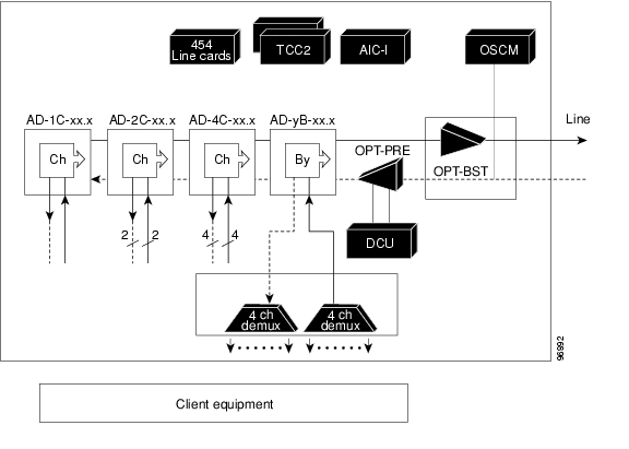
The OADM cards that can be used in this type of configuration are the AD-1C-xx.x, AD-2C-xx.x, AD-4C-xx.x, and AD-1B-xx.x. You can also use the AD-4B-xx.x card and up to four 4MD-xx.x cards. The OPT-PRE and/or OPT-BST amplifiers can be used. The OPT-PRE or OPT-BST configuration depends on the node loss and the span loss. When the OPT-BST is not installed, the OSC-CSM card must be used instead of the OSCM card. Figure 3-21 shows a channel flow example of a scalable terminal node configuration.
Figure 3-21 Scalable Terminal Channel Flow
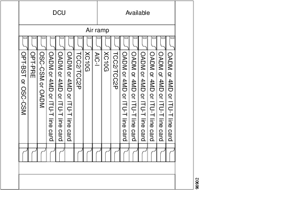
A scalable terminal node can be created by using band and/or channel OADM filter cards. This node type is the most flexible of all node types, because the OADM filter cards can be configured to accommodate node traffic. If the node does not contain amplifiers, it is considered a passive hybrid terminal node. Figure 3-22 shows an example of a scalable terminal node configuration. This node type can be used without add or drop cards.
Figure 3-22 Scalable Terminal Node Configuration
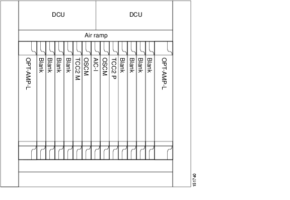
3.1.7.3 L-Band Terminal Node
A terminal node is a single ONS 15454 node equipped with two TCC2/TCC2P cards, an OSCM or OSC-CSM card, an OPT-BST-L card, an OPT-AMP-L card, one 32WSS-L card, and one 32DMX-L card.
Terminal nodes can be either east or west. In west terminal nodes, the cards are installed in the east slots (Slots 1 through 6). In east terminal nodes, cards are installed in the west slots (Slots 12 through 17). A hub node can be changed into a terminal node by removing either the east or west cards. Figure 3-20 shows an example of an east terminal configuration. The channel flow for a terminal node is the same as the hub node, as shown in Figure 3-18.
Note
Figure 3-23 L-Band 32-Channel Terminal Site Layout
3.1.8 DWDM and TDM Hybrid Node Configurations
The node configuration is determined by the type of card that is installed in an ONS 15454 hybrid node. The ONS 15454 supports the following DWDM and TDM hybrid node configurations:
•
•
•
•
Note
3.1.8.1 Hybrid Terminal Node
A hybrid terminal node is a single ONS 15454 node equipped with at least one 32MUX-O card, one 32DMX-O card, two TCC2/TCC2P cards, and TDM cards. If the node is equipped with OPT-PRE or OPT-BST amplifiers, it is considered an amplified terminal node. The node becomes passive if the amplifiers are removed. The hybrid terminal node type is based on the DWDM terminal node type described in the "Terminal Node" section. Figure 3-24 shows an example of an amplified hybrid terminal node configuration.
Figure 3-24 Amplified Hybrid Terminal
Figure 3-25 shows an example of a passive hybrid terminal node configuration.
Figure 3-25 Passive Hybrid Terminal
3.1.8.2 Hybrid OADM Node
A hybrid OADM node is a single ONS 15454 node equipped with at least one AD-xC-xx.x card or one AD-xB-xx.x card, and two TCC2/TCC2P cards. The hybrid OADM node type is based on the DWDM OADM node type previously described in the "C-Band OADM Node" section. TDM cards can be installed in any available multispeed slot. Review the plan produced by Cisco MetroPlanner to determine slot availability. Figure 3-26 shows an example of an amplified hybrid OADM node configuration. The hybrid OADM node can also become passive by removing the amplifier cards.
Figure 3-26 Hybrid Amplified OADM
3.1.8.3 Hybrid Line Amplifier Node
A hybrid line amplifier node is a single ONS 15454 node with open slots for both TDM and DWDM cards. Figure 3-27 shows an example of a hybrid line amplifier node configuration.
Note
Figure 3-27 Hybrid Line Amplifier
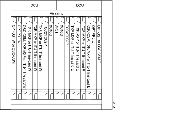
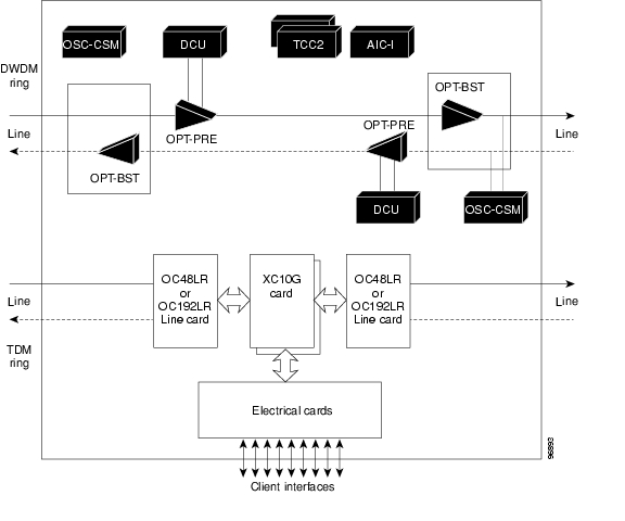
A hybrid line node is another example of the hybrid line amplifier OADM node. A hybrid line node is single ONS 15454 node equipped with OPT-PRE amplifiers, OPT-BST amplifiers, and TCC2/TCC2P cards for each line direction. Both types of amplifiers can be used or just one type of amplifier. Attenuators might also be required between each preamplifier and booster amplifier to match the optical input power value and to maintain the amplifier gain tilt value. TDM cards can be installed in any available multispeed slot. Review the plan produced by Cisco MetroPlanner to determine slot availability. Figure 3-28 shows a channel flow example of a hybrid line node configuration. Since this node contains both TDM and DWDM rings, both TDM and DWDM rings should be terminated even if no interactions are present between them.
Figure 3-28 Hybrid Line Amplifier Channel Flow
3.1.8.4 Amplified TDM Node
An amplified TDM node is a single ONS 15454 node that increases the span length between two ONS 15454 nodes that contain TDM cards and optical amplifiers. There are three possible configurations for an amplified TDM node:
•
•
•
The client cards that can be used in an amplified TDM node are:
•
•
•
•
•
•
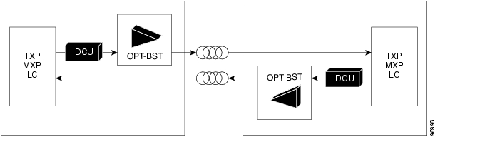
Figure 3-29 shows the first amplified TDM node configuration with an OPT-BST amplifier.
Figure 3-29 Amplified TDM Example with an OPT-BST Amplifier
Figure 3-30 shows the first amplified TDM node channel flow configuration with OPT-BST amplifiers.
Figure 3-30 Amplified TDM Channel Flow Example With OPT-BST Amplifiers
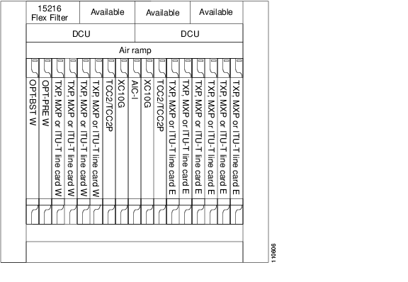
Figure 3-31 shows the second amplified TDM node configuration with client cards, AD-1C-xx.x cards, OPT-BST amplifiers, OPT-PRE amplifiers, and FlexLayer filters.
Figure 3-31 Amplified TDM Example with FlexLayer Filters
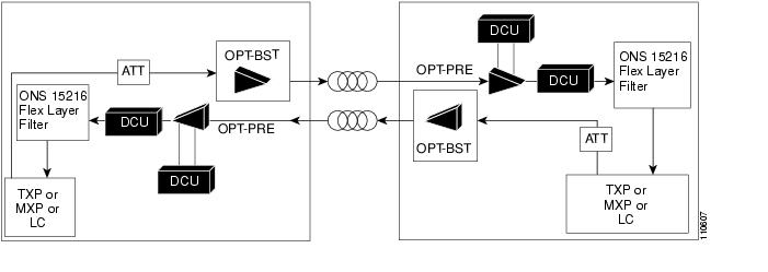
Figure 3-32 shows the second amplified TDM node channel flow configuration with client cards, OPT-BST amplifiers, OPT-PRE amplifiers, and FlexLayer filters.
Figure 3-32 Amplified TDM Channel Flow Example With FlexLayer Filters
Figure 3-33 shows the third amplified TDM channel flow configuration with client cards, OPT-BST amplifiers, OPT-PRE amplifiers, AD-1C-xx.x cards, and OSC-CSM cards.
Figure 3-33 Amplified TDM Channel Flow Example With Amplifiers, AD-1C-xx.x Cards, and OSC-CSM Cards
3.1.9 Transponder (Client) Shelf Layout
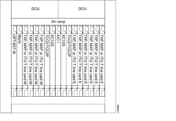
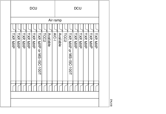
Transponder and muxponder cards can be installed in any ONS 15454 slot that is marked with the orange circle symbol. Figure 3-34 shows transponder shelf layout.
Figure 3-34 Transponder Shelf Layout
3.1.10 Inter-Shelf Communications
A typical Multiservice Transport Platform (MSTP) node foresees a number of units that cannot be equipped in a single shelf. It might not be possible to manage the optical shelf and the transponder shelf as different nodes.
A multishelf (MS) node can aggregate up to eight shelves, none of them equipped with cross-connect (XC) cards. All these shelves must be collocated at the same site at a maximum distance of 328 feet (100 m) from the Ethernet switches that are used to support the communication LAN.
The MS feature is not supported for the Multiservice Provisioning Platform (MSPP). Multishelf nodes carry a single public IP address. All aggregated shelves have a common management interface (CTC/CTM/TL1/SNMP/HTTP).
3.1.10.1 Definitions
The following definitions are applicable to inter-shelf communications:
•
•
•
3.1.10.2 Communication Layer
Supervision of an MS mode is distributed among TCC2/TCC2Ps in different shelves. The TCCs require communication channel between them, which is accomplished with an Ethernet LAN.
For physical connections between PROT ports, and between an MS-ISC-100T NC port and a TCC2/TCC2P FP port, you must use common CAT-5 Ethernet cables. These cables are internal to the NC shelf and are part of the MS bundle.
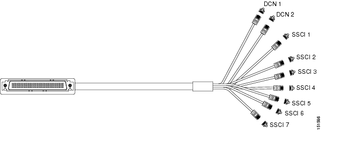
Physical connection starting from DCN and SSC ports use a special multiport cable that must be installed (see Figure 3-35).
Figure 3-35 Ethernet Adapter Cable
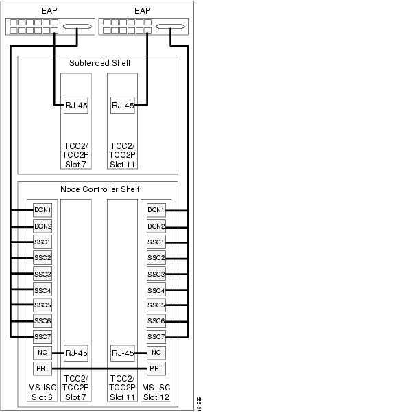
User interfaces (TCC, CTM, Tl1 OSS) and SSC ports must be connected to the patch panel using common CAT-5 Ethernet cables. Patch-panel ports are labeled as MS-ISC-100T ports, which use the same color code. Figure 3-36 shows a rack with two shelves in it. It follows the cabling rules described in this section.
Figure 3-36 Connecting the EAP to the Node Controller and Subtending Shelf
A multishelf node can use both TCC2 and TCC2P cards. A mix of TCC2 and TCC2P is supported in both NC and SSC shelves.
3.1.10.3 Multishelf Layout
MS mode does not impose any constraint about layout apart from equipping MS-ISC-100T cards in the NC shelf. The following are the most common configurations:
•
•
These are the recommended configurations and are designed by Cisco MetroPlanner. Considering the first case, all empty slots in the NC shelves can be equipped with TXPs/MXPs.
These layouts are automatically detected by the CTC software. In these two cases, you can create the node patchcord tree without any manual intervention. This feature is not supported if units are provisioned or equipped according to different rules.
In Software Release 7.0, the patchcord tree has been extended to include a link between the TXP/MXP OCH Trunk port a nd the OCH-Filter port. This patchcord can be automatically created only if a TXP/MXP has been previously tuned on one of the supported wavelengths.
In the east/west protected layout, you must implement configurations that are reliable against electrical power outages. Neither east nor west terminated traffic will be lost in case of a single shelf shut down.
In a typical layout, TXPs or MXPs facing east and west can be equipped in three different ways:
•
•
•
These rules are also implemented by Cisco MetroPlanner 7.0.
ANSI and ETSI racks can equip a number of 15454 shelves. An ANSI rack can equip four 15454 shelves, while an ETSI rack can equip three 15454 shelves. Fully-equipped racks do not have space for an ONS 15216 DCU Shelf (1 RU), a Patch Panel Shelf (1 RU), a Fiber Storage (1 RU), an ONS 15216 Y-Cable Shelf (1 RU), or an Air Ramp (1 RU).
To create space for one of these service shelves, the number of 15454 shelves must be reduced to three in an ANSI rack and to two in an ETSI rack. In all layouts, unallocated space for MSTP shelves can be used to install MSPP shelves. In this case, MSTP shelves will build a Multishelf Node Element (MSNE); each of the MSPP shelves will be a single-shelf node.
A fully equipped maximum MSNE configuration (32 bidirectional channels) requires eight shelves in an east/west protected layout, seven in all the others. These shelves can be equipped in different racks: a maximum of eight for protected configurations, seven for all others.
3.1.10.4 DCC/GCC/OSC Termination
A multishelf MSTP node provides the same DCN communication channels as a single-shelf node:
•
•
Support for intelligent network applications requires two OSC links between every two MSTP nodes. This assumption is still valid in an MS environment where an OSC-CSM or OSCM card is required for each of terminated spans. An OSC link between two nodes cannot be replaced by an equivalent GCC/DCC link terminated on the same set of nodes. OSC links are mandatory and they can be used to connect nodes to gateway network element (GNE). This implies that TXP shelves can be monitored remotely and this reduces the number of GCC/DCC links requested by DCN.
The maximum number of DCC/GCC/OSC terminations that are supported in a multishelf node is 48. These paths can be terminated in any of the aggregated shelves.
3.1.10.5 Circuit Overhead
Circuit overhead is extracted by AIC-I physical ports. In a multishelf environment, overhead byte circuits are not routed inside an MSNE node. To extract overhead bytes, the shelf must be equipped with an AIC-I card.
3.1.10.6 Timing Tree
Aggregating many shelves in a single multishelf network element (NE) does not imply any specific requirement related to timing. For timing, each shelf must have a single-shelf node that can be used as timing source line, TCC clock, or building integrated timing supply (BITS) source lines.
If you want to synchronize the entire MSNE with a single timing source, you must configure BITS IN and BITS OUT ports on different shelves correctly.
3.1.10.7 Automatic Node Provisioning
Cisco MetroPlanner provides a node bill of materials (BOM) and node layout, including the physical position (slot) of each card. The Automatic Node Provisioning file contains two main sections:
•
•
A card parameter section is also available, though it is significant for L-band cards only. Node layout includes shelves, and the cards inside the shelves. In the DWDM > ANS tab, CTC provides a wizard that allows you to manage XML files. Cisco MetroPlanner prepares a single XML file for each designed network.
You can choose to perform node layout provisioning, ANS parameters provisioning, or both. Node layout provisioning includes the following components:
•
•
You can preview provisioning data parameters before applying them. Provisioning results are displayed on the monitor, and are logged into a specified file.
The Import function that was available on the ANS-WDM > Provisioning tab is no longer supported because the wizard now provisions ANS parameters. The provisioning wizard is not backward compatible and hence cannot manage ANS files in the previous ASCII format.
The main provisioning report could have the following results:
•
•
•
3.2 Site Drawings
Typically, up to three ONS 15454 shelves can be mounted in a standard ANSI 7-foot bay (with a low-profile fuse panel) if a dispersion compensation shelf assembly is required. The remaining space can be used to install up to nine 1 rack unit (RU) shelves, including:
•
•
•
•
•
3.2.1 ROADM and Hub Node
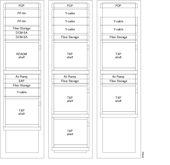
Figure 3-37 shows the site configuration for an ROADM and hub node.
Figure 3-37 ROADM and Hub Node
3.2.2 Terminal Site
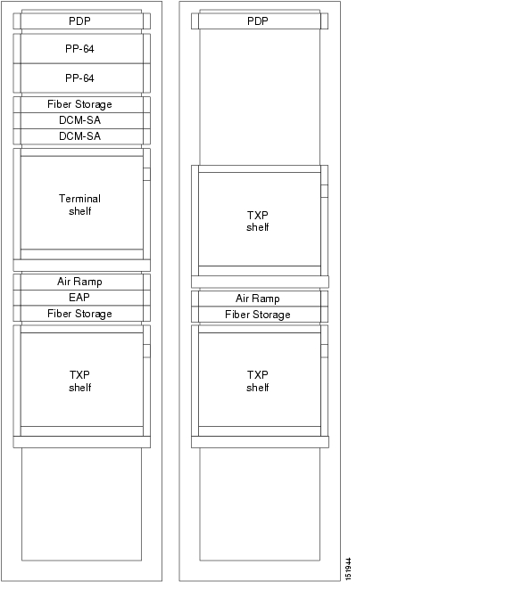
Figure 3-38 shows the configuration for a terminal site.
Figure 3-38 Terminal Site
3.2.3 Line Amplifier Site
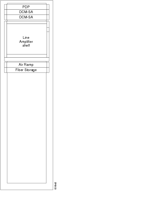
Figure 3-39 shows the configuration for a line amplifier site.
Figure 3-39 Line Amplifier Site
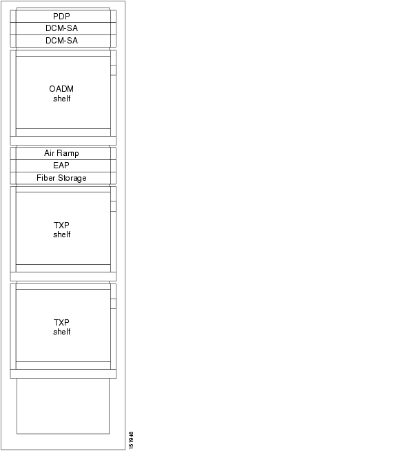
3.2.4 OADM Node
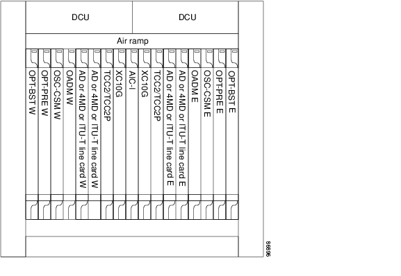
Figure 3-40 shows the configuration for an OADM node.
Figure 3-40 OADM Node
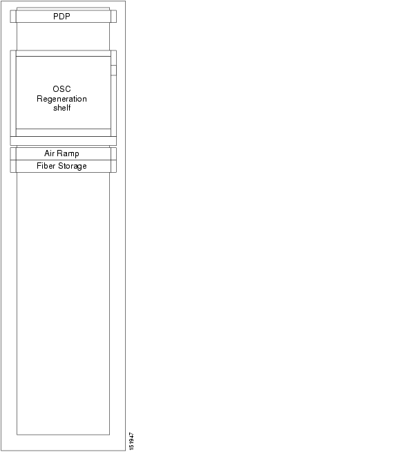
3.2.5 OSC Regeneration Site
Figure 3-41 shows the configuration for an optical service channel (OSC) regeneration site.
Figure 3-41 OSC Regeneration Site
![]()
![]()
![]()
![]()
![]()
![]()
![]()
![]()
Posted: Tue Sep 18 06:06:45 PDT 2007
All contents are Copyright © 1992--2007 Cisco Systems, Inc. All rights reserved.
Important Notices and Privacy Statement.