|
|

Table Of Contents
6.1 Network Topology Discovery
6.2.1 APC at the Amplifier Card Level
6.2.2 APC at the Node and Network Levels
6.3 ROADM Power Equalization Monitoring
6.5 Network Optical Safety--Automatic Laser Shutdown
6.5.1 Automatic Power Reduction
6.6 Network-Level Gain-Tilt Management of Optical Amplifiers
6.6.1 Gain Tilt Control at the Card Level
6.6.2 System Level Gain Tilt Control
6.7.1 Automatic Node Setup Parameters
6.7.2 View and Provision ANS Parameters
Network Applications
This chapter describes Cisco ONS 15454 DWDM networks and includes the following sections:
•
ROADM Power Equalization Monitoring
•
•
6.1 Network Topology Discovery
Each ONS 15454 DWDM node has a network topology discovery function that can:
•
•
•
ONS 15454 DWDM nodes use node services protocol (NSP) to update nodes automatically whenever a change in the network occurs. NSP uses two information exchange mechanisms: hop-by-hop message protocol and broadcast message protocol. Hop-by-hop message protocol elects a master node and exchanges information between nodes in a sequential manner, which instigates a token ring protocol. In a token ring protocol:
•
•
•
NSP broadcast message protocol distributes information that can be shared by all ONS 15454 DWDM nodes on the same network. Broadcast message delivery is managed independently from delivery of the two tokens. Moreover, no synchronization among broadcast messages is required; every node is authorized to send a broadcast message any time it is necessary.
6.2 Automatic Power Control
The ONS 15454 automatic power control (APC) feature performs the following functions:
•
•
•
Note
Amplifier software uses a gain control loop with fast transient suppression to keep the channel power constant regardless of any changes in the number of channels. Amplifiers monitor the changes to the input power and change the output power according to the calculated gain setpoint. The shelf controller software emulates the output power control loop to adjust for fiber degradation. To perform this function, the TCC2 or TCC2P (shelf controller) card needs the channel distribution, which is provided by a signaling protocol, and the expected per-channel power, which you can provision. The TCC2/TCC2P card compares the actual amplifier output power with the expected amplifier output power and modifies the setpoints if any discrepancies occur.
6.2.1 APC at the Amplifier Card Level
In constant gain mode, the amplifier power out control loop performs the following input and output power calculations, where "G" represents gain and "t" represents time.
Pout (t) = G * Pin (t) (mW)
Pout (t) = G + Pin (t) (dB)
In a power-equalized optical system, the total input power is proportional to the number of channels. The amplifier software compensates for any variation of the input power due to changes in the number of channels carried by the incoming signal.
Amplifier software identifies changes in the read input power in two different instances, t1 and t2, as a change in the carried traffic. The letters m and n in the following formula represent two different channel numbers. Pin/ch represents the per-channel input power:
Pin (t1)= nPin/ch
Pin (t2) = mPin/ch
Amplifier software applies the variation in the input power to the output power with a reaction time that is a fraction of a millisecond. This keeps the power constant on each channel at the output amplifier, even during a channel upgrade or a fiber cut.
Amplifier parameters are configured using east and west conventions for ease of use. Selecting "west" provisions parameters for the preamplifier receiving from the west and the booster amplifier transmitting to the west. Selecting "east" provisions parameters for the preamplifier receiving from the east and the booster amplifier transmitting to the east.
Starting from the expected per-channel power, the amplifiers automatically calculate the gain setpoint after the first channel is provisioned. An amplifier gain setpoint is calculated in order to make it equal to the loss of the span preceding the amplifier. After the gain is calculated, the setpoint is no longer changed by the amplifier. Amplifier gain is recalculated every time the number of provisioned channels returns to zero. If you need to force a recalculation of the gain, move the number of channels back to zero.
6.2.2 APC at the Node and Network Levels
The amplifier adjusts the gain to compensate for span loss. Span loss can change due to aging fiber and components, or to changes in operating conditions. To correct the gain or express variable optical attenuator (VOA) setpoints, APC calculates the difference between the power value read by the photodiodes and the expected power value. The expected power values are calculated using:
•
•
•
Channel distribution is determined by the sum of the provisioned and failed channels. Information about provisioned wavelengths is sent to APC on the applicable nodes during circuit creation. Information about failed channels is collected through a signaling protocol that monitors alarms on ports in the applicable nodes and distributes that information to all the other nodes in the network.
ASE calculations purify the noise from the power level reported from the photodiode. Each amplifier can compensate for its own noise, but cascaded amplifiers cannot compensate for ASE generated by preceding nodes. The ASE effect increases when the number of channels decreases; therefore, a correction factor must be calculated in each amplifier of the ring to compensate for ASE build-up.
APC is a network-level feature. The APC algorithm designates a master node that is responsible for starting APC hourly or every time a new circuit is provisioned or removed. Every time the master node signals for APC to start, gain and VOA setpoints are evaluated on all nodes in the network. If corrections are needed in different nodes, they are always performed sequentially following the optical paths starting from the master node.
APC corrects the power level only if the variation exceeds the hysteresis thresholds of +/- 0.5 dB. Any power level fluctuation within the threshold range is skipped because it is considered negligible. Because APC is designed to follow slow time events, it skips corrections greater than 3 dB. This is the typical total aging margin that is provisioned during the network design phase. After you provision the first channel or the amplifiers are turned up for the first time, APC does not apply the 3 dB rule. In this case, APC corrects all the power differences to turn up the node.
Note
To avoid large power fluctuations, APC adjusts power levels incrementally. The maximum power correction is +/- 0.5 dB. This is applied to each iteration until the optimal power level is reached. For example, a gain deviation of 2 dB is corrected in four steps. Each of the four steps requires a complete APC check on every node in the network. APC can correct up to a maximum of 3 dB on an hourly basis. If degradation occurs over a longer time period, APC will compensate for it by using all margins that you provision during installation.
When no margin is available, adjustments cannot be made because setpoints exceed ranges. APC communicates the event to CTC, CTM, and TL1 through an APC Fail condition. APC will clear the APC fail condition when the setpoints return to the allowed ranges.
APC automatically disables itself when:
•
•
•
•
•
The APC state (Enable/Disable) is located on every node and can be retrieved by the CTC or TL1 interfaces. If an event that disables APC occurs in one of the network nodes, APC is disabled on all the others and the APC state changes to DISABLE - INTERNAL. The disabled state is raised only by the node where the problem occurred to simplify troubleshooting.
APC raises the following standing conditions at the port level in CTC, TL1, and Simple Network Management Protocol (SNMP):
•
•
After the error condition is cleared, signaling protocol enables APC on the network and the APC DISABLE - INTERNAL condition is cleared. Because APC is required after channel provisioning to compensate for ASE effects, all optical channel network connection (OCHNC) and optical channel client connection (OCHCC) circuits that you provision during the disabled APC state are kept in the Out-of-Service and Autonomous, Automatic In-Service (OOS-AU,AINS) (ANSI) or Unlocked-disabled,automaticInService (ETSI) service state until APC is enabled. OCHNCs and OCHCCs automatically go into the In-Service and Normal (IS-NR) (ANSI) or Unlocked-enabled (ETSI) service state only after APC is enabled.
6.2.3 Managing APC
The automatic power control status is indicated by four APC states shown in the node view status area:
•
•
•
•
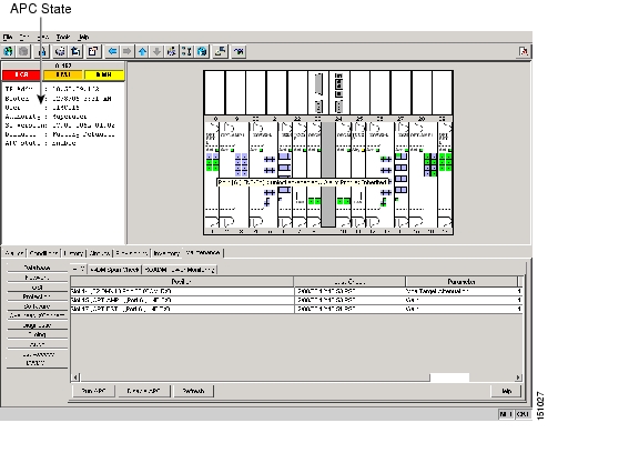
You can view the automatic power control information and disable and enable APC manually on the Maintenance > DWDM > APC tab ( Figure 6-1).
Caution
Figure 6-1 Automatic Power Control
The APC subtab provides the following information:
•
•
•
•
•
Table 6-1 APC-Managed Parameters
OPT-BST
LINE-3-TX
•
•
OPT-PRE
LINE-1-TX
•
•
AD-xB-xx.x
LINE-1-TX
BAND-n1 -TX
VOA Target Attenuation
AD-1C-xx.x
AD-2C-xx.x
LINE-1-TX
VOA Target Attenuation
AD-4C-xx.x
LINE-1-TX
CHAN-n2 -TX
VOA Target Attenuation
32DMX
LINE-1-TX
VOA Target Attenuation
1 n = 1-8
2 n = 1-32
6.3 ROADM Power Equalization Monitoring
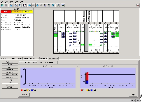
Reconfigurable optical add/drop multiplexing (ROADM) nodes allow you to monitor the 32WSS card equalization functions on the Maintenance > DWDM > Power Monitoring tab ( Figure 6-2). The tab shows the input channel power (Padd), the express or pass-through (Ppt) power, and the power level at output (Pout).
Figure 6-2 Power Monitoring Subtab
6.4 Span Loss Verification
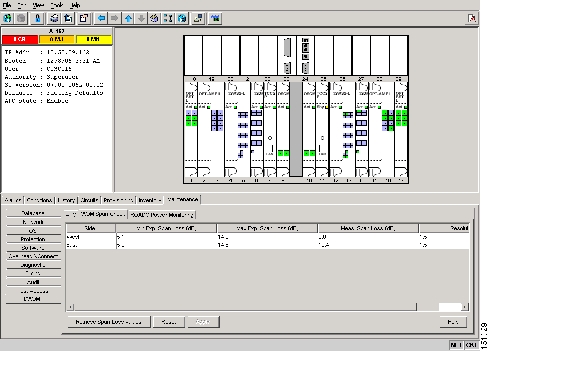
Span loss measurements can be performed from the Maintenance > DWDM > WDM Span Check tab ( Figure 6-3). The CTC span check compares the far-end optical service channel (OSC) power with the near-end OSC power. A Span Loss Out of Range condition is raised when the measured span loss is higher than the maximum expected span loss. It is also raised when the measured span loss is lower than the minimum expected span loss and the difference between the minimum and maximum span loss values is greater than 1 dB. The minimum and maximum expected span loss values are calculated by Cisco MetroPlanner for the network and imported into CTC. However, you can manually change the minimum and expected span loss values.
CTC span loss measurements provide a quick span loss check and are useful whenever changes to the network occur, for example after you install equipment or repair a broken fiber. CTC span loss measurement resolutions are:
•
•
For ONS 15454 span loss measurements with higher resolutions, an optical time domain reflectometer (OTDR) must be used.
Figure 6-3 Span Loss Verification
6.5 Network Optical Safety--Automatic Laser Shutdown
Automatic laser shutdown (ALS) is a key component of the DWDM network optical safety. If a fiber break occurs on the network, ALS automatically shuts down the OSCM and OSC-CSM OSC laser output power and the optical amplifiers contained in the OPT-BST cards. The card-level, Maintenance > ALS subtab provides the following ALS management options for OSCM, OSC-CSM, and OPT-BST cards:
•
•
Note
•
•
A network optical safety strategy is achieved through the ALS settings on the OPT-BST, OSCM, and OSC-CSM cards. When ALS is enabled on these cards, a network safety mechanism goes into effect in the event of a system failure. However, ALS is also provided on the transponder (TXP) and muxponder (MXP) cards. As long as a network uses OPT-BST, OSCM, and OSC-CSM cards and ALS is enabled on them, ALS does not need to be enabled on the TXPs or MXPs; in fact, ALS is disabled on TXP and MXP by default, and the network optical safety is not impacted.
However, if TXPs and MXPs are connected directly to each other without passing through a DWDM layer, ALS should be enabled on them. The ALS protocol goes into effect when a fiber is cut, enabling some degree of network point-to-point bidirectional traffic management between those cards.
In addition, if ALS is disabled on the DWDM network (ALS is disabled on the OPT-BST, OSCM, and OSC-CSM cards), ALS can be enabled on the TXP and MXP cards to provide some laser management in the event of a fiber break in the network between the cards.
6.5.1 Automatic Power Reduction
Automatic power reduction (APR) is controlled by the software and is not user configurable. During amplifier restart after a system failure, the amplifier (OPT-BST, for example) operates in pulse mode and an automatic power reduction level is activated so that the Hazard Level 1 power limit is not exceeded. This is done to ensure personnel safety.
When a system failure occurs (cut fiber or equipment failure, for example) and ALS Auto Restart is enabled, a sequence of events is placed in motion to shut down the amplifier laser power, then automatically restart the amplifier after the system problem is corrected. As soon as a loss of optical payload and OSC is detected at the far end, the far-end amplifier shuts down. The near-end amplifier then shuts down because in similar fashion, it detects a loss of payload and OSC due to the far-end amplifier shutdown. At this point, the near end attempts to establish communication to the far end using the OSC laser transmitter. To do this, the OSC emits a two-second pulse at very low power (maximum of 0 dB) and waits for a similar two-second pulse in response from the far-end OSC laser transmitter. If no response is received within 100 seconds, the near end tries again. This process continues until the near end receives a two-second response pulse from the far end. This is an indication that the system failure has been corrected and that there is full continuity in the fiber between the two ends.
After the OSC communication has been established, the near-end amplifier is configured by the software to operate in pulse mode at a reduced power level. It emits a nine-second laser pulse with an automatic power reduction to +8 dB. This level assures that Hazard Level 1 is not exceeded, for personnel safety, even though the establishment of successful OCS communication has assured that any broken fiber has been fixed. If the far-end amplifier responds with a nine-second pulse within 100 seconds, both amplifiers are changed from pulse mode at reduced power to normal operating power mode.
For a direct connection between TXP or MXP cards, when ALS Auto Restart is enabled and the connections do not pass through a DWDM layer, a similar process takes place. However, because the connections do not go through any amplifier or OSC cards, the TXP or MXP cards attempt to establish communication directly between themselves after a system failure. This is done using a two-second restart pulse, in a manner similar to that previously described between OSCs at the DWDM layer. The power emitted during the pulse is below Hazard Level 1.
Warning
Note
6.5.2 Fiber Cut Scenarios
In the following paragraphs, four ALS scenarios are given:
•
•
•
•
6.5.2.1 Scenario 1: Fiber Cut in Nodes Using OPT-BST/OPT-BST-E Cards
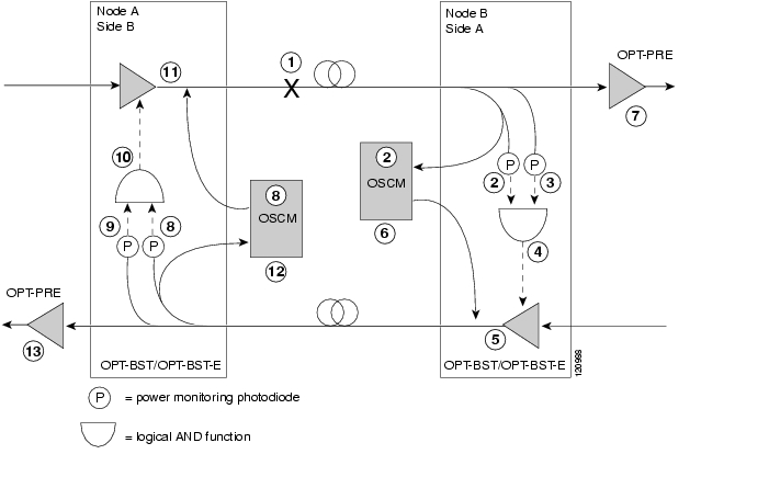
Figure 6-4 shows nodes using OPT-BST/OPT-BST-E cards with a fiber cut between them.
Figure 6-4 Nodes Using OPT-BST/OPT-BST-E Cards
Two photodiodes at Node B monitor the received signal strength for the optical payload and OSC signals. When the fiber is cut, an LOS is detected at both of the photodiodes. The AND function then indicates an overall LOS condition, which causes the OPT-BST/OPT-BST-E transmitter, OPT-PRE transmitter, and OSCM lasers to shut down. This in turn leads to a LOS for both the optical payload and OSC at Node A, which causes Node A to turn off the OSCM, OPT-PRE transmitter, and OPT-BST/OPT-BST-E transmitter lasers. The sequence of events after a fiber cut is as follows (refer to the numbered circles in Figure 6-4):
1.
2.
3.
4.
5.
6.
7.
8.
9.
10.
11.
12.
13.
When the fiber is repaired, either an automatic or manual restart at the Node A OPT-BST/OPT-BST-E transmitter or at the Node B OPT-BST/OPT-BST-E transmitter is required. A system that has been shut down is reactivated through the use of a restart pulse. The pulse is used to signal that the optical path has been restored and transmission can begin. For example, when the far end, Node B, receives a pulse, it signals to the Node B OPT-BST/OPT-BST-E transmitter to begin transmitting an optical signal. The OPT-BST/OPT-BST-E receiver at Node A receives that signal and signals the Node A OPT-BST/OPT-BST-E transmitter to resume transmitting.
Note
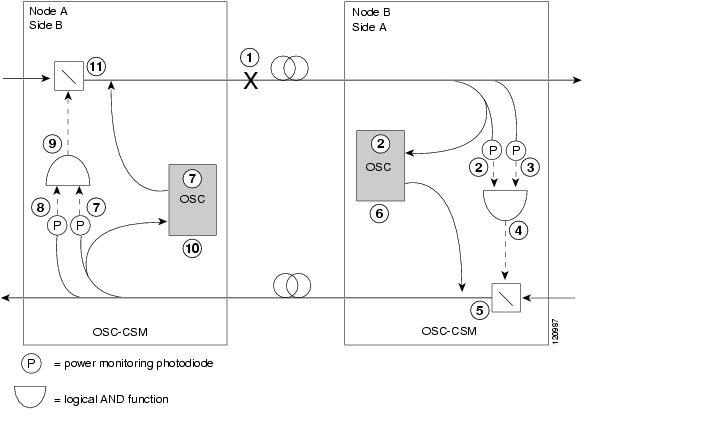
6.5.2.2 Scenario 2: Fiber Cut in Nodes Using OSC-CSM Cards
Figure 6-5 shows nodes using OSC-CSM cards with a fiber cut between them.
Figure 6-5 Nodes Using OSC-CSM Cards
Two photodiodes at the Node B OSC-CSM card monitor the received signal strength for the received optical payload and OSC signals. When the fiber is cut, LOS is detected at both of the photodiodes. The AND function then indicates an overall LOS condition, which causes the Node B OSC laser to shut down and the optical switch to block traffic. This in turn leads to LOS for both the optical payload and OSC signals at Node A, which causes Node A to turn off the OSC laser and the optical switch to block outgoing traffic. The sequence of events after a fiber cut is as follows (refer to the numbered circles in Figure 6-5):
1.
2.
3.
4.
5.
6.
7.
8.
9.
10.
11.
When the fiber is repaired, either an automatic or manual restart at the Node A OSC-CSM OSC or at the Node B OSC-CSM OSC is required. A system that has been shut down is reactivated through the use of a restart pulse. The pulse is used to signal that the optical path has been restored and transmission can begin. For example, when the far-end Node B receives a pulse, it signals to the Node B OSC to begin transmitting its optical signal and for the optical switch to pass incoming traffic. The OSC-CSM at Node A then receives the signal and tells the Node A OSC to resume transmitting and for the optical switch to pass incoming traffic.
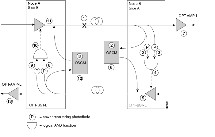
6.5.2.3 Scenario 3: Fiber Cut in Nodes Using OPT-BST-L Cards
Figure 6-6 shows nodes using OPT-BST-L cards with a fiber cut between them.
Figure 6-6 Nodes Using OPT-BST-L Cards
Two photodiodes at Node B monitor the received signal strength for the optical payload and OSC signals. When the fiber is cut, an LOS is detected at both of the photodiodes. The AND function then indicates an overall LOS condition, which causes the OPT-BST-L transmitter and OSCM lasers to shut down. This in turn leads to a LOS for both the optical payload and OSC at Node A, which causes Node A to turn off the OSCM OSC transmitter and OPT-BST-L amplifier lasers. The sequence of events after a fiber cut is as follows (refer to the numbered circles in Figure 6-6):
1.
2.
3.
4.
5.
6.
7.
8.
9.
10.
11.
12.
13.
When the fiber is repaired, either an automatic or manual restart at the Node A OPT-BST-L transmitter or at the Node B OPT-BST-L transmitter is required. A system that has been shut down is reactivated through the use of a restart pulse. The pulse is used to signal that the optical path has been restored and transmission can begin. For example, when the far end, Node B, receives a pulse, it signals to the Node B OPT-BST-L transmitter to begin transmitting an optical signal. The OPT-BST-L receiver at Node A receives that signal and signals the Node A OPT-BST-L transmitter to resume transmitting.
Note
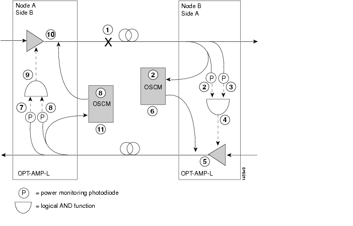
6.5.2.4 Scenario 4: Fiber Cut in Nodes Using OPT-AMP-L (OPT-BST Mode) Cards
Figure 6-7 shows nodes using OPT-AMP-L (in OPT-BST mode) cards with a fiber cut between them.
Figure 6-7 Nodes Using OPT-AMP-L Cards
Two photodiodes at Node B monitor the received signal strength for the optical payload and OSC signals. When the fiber is cut, an LOS is detected at both of the photodiodes. The AND function then indicates an overall LOS condition, which causes the OPT-AMP-L amplifier transmitter and OSCM OSC lasers to shut down. This in turn leads to a LOS for both the optical payload and OSC at Node A, which causes Node A to turn off the OSCM OSC and OPT-AMP-L amplifier lasers. The sequence of events after a fiber cut is as follows (refer to the numbered circles in Figure 6-7):
1.
2.
3.
4.
5.
6.
7.
8.
9.
10.
11.
When the fiber is repaired, either an automatic or manual restart at the Node A OPT-AMP-L transmitter or at the Node B OPT-AMP-L transmitter is required. A system that has been shut down is reactivated through the use of a restart pulse. The pulse is used to signal that the optical path has been restored and transmission can begin. For example, when the far end, Node B, receives a pulse, it signals to the Node B OPT-AMP-L transmitter to begin transmitting an optical signal. The OPT-AMP-L receiver at Node A receives that signal and signals the Node A OPT-AMP-L transmitter to resume transmitting.
Note
6.6 Network-Level Gain-Tilt Management of Optical Amplifiers
The ability to control and adjust per-channel optical power equalization is a principal feature of ONS 15454 DWDM metro core network applications. A critical parameter to assure optical spectrum equalization throughout the DWDM system is the gain flatness of erbium-doped fiber amplifiers (EDFAs).
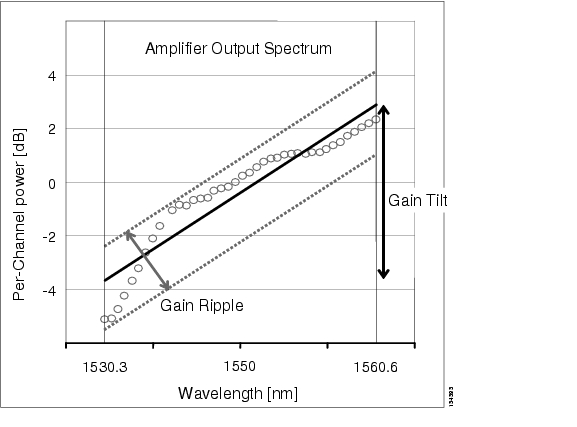
Two items, gain tilt and gain ripple, are factors in the power equalization of optical amplifier cards such as the OPT-BST and OPT-PRE. Figure 6-8 shows a graph of the amplifier output power spectrum and how it is affected by gain tilt and gain ripple.
Figure 6-8 Effect of Gain Ripple and Gain Tilt on Amplifier Output Power
Gain ripple and gain tilt are defined as follows:
•
•
Gain tilt is the only contribution to the power spectrum disequalization that can be compensated at the card level. A VOA internal to the amplifier can be used to compensate for gain tilt.
An optical spectrum analyzer (OSA) is used to acquire the output power spectrum of an amplifier. The OSA shows the peak-to-peak difference between the maximum and minimum power levels, and takes into account the contributions of both gain tilt and gain ripple.
Note
6.6.1 Gain Tilt Control at the Card Level
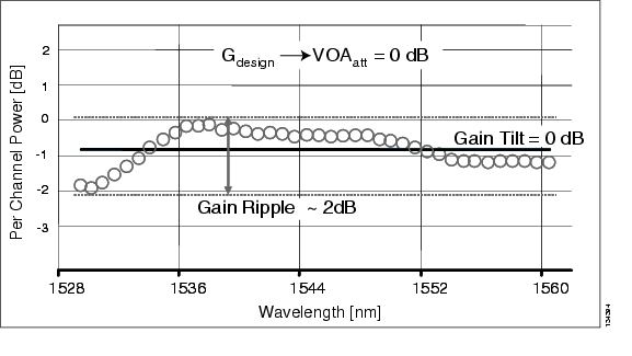
The OPT-BST and OPT-PRE amplifier cards have a flat output (gain tilt = 0 dB) for only a specific gain value (Gdesign), based on the internal optical design (see Figure 6-9).
Figure 6-9 Flat Gain (Gain Tilt = 0 dB)
If the working gain setpoint of the amplifier is different from Gdesign, the output spectrum begins to suffer a gain tilt variation.
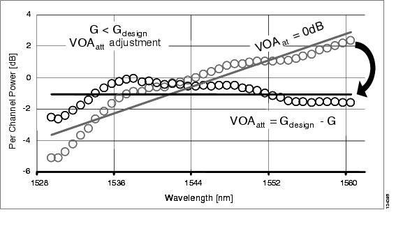
In order to compensate for the absolute value of the increase of the spectrum tilt, the OPT-BST and OPT-PRE cards automatically adjust the attenuation of the VOA to maintain a flat power profile at the output, as shown in Figure 6-10.
Figure 6-10 Effect of VOA Attenuation on Gain Tilt
The VOA attenuator automatic regulation guarantees (within limits) a zero tilt condition in the EDFA for a wide range of possible gain setpoint values.
Table 6-2 shows the flat output gain range limits for the OPT-BST and OPT-PRE cards, as well as the maximum (worst case) values of gain tilt and gain ripple expected in the specific gain range. OPT-AMP-L card can also function as an OPT-BST or OPT-PRE.
Table 6-2 Flat Output Gain Range Limits
OPT-BST
G < 20 dB
0.5 dB
1.5 dB
OPT-PRE
G < 21 dB
0.5 dB
1.5 dB
If the operating gain value is outside of the range shown in Table 6-2, the EDFA introduces a tilt contribution for which the card itself cannot directly compensate. This condition is managed in different ways, depending the amplifier card type:
•
•
6.6.2 System Level Gain Tilt Control
System level gain tilt control for OPT-PRE cards is achievable with two main scenarios:
•
•
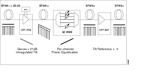
6.6.2.1 System Gain Tilt Compensation Without ROADM Nodes
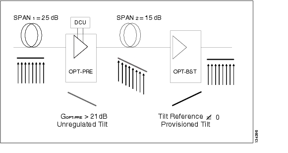
When an OPT-PRE card along a specific line direction (west-to-east or east-to-west) is working outside the flat output gain range (G > 21 dB), the unregulated tilt is compensated for in spans not connected to ROADM nodes by configuring an equal but opposite tilt on one or more of the amplifiers in the downstream direction. The number of downstream amplifiers involved depends on the amount of tilt compensation needed and the gain setpoint of the amplifiers that are involved. See Figure 6-11.
Figure 6-11 System Tilt Compensation Without an ROADM Node
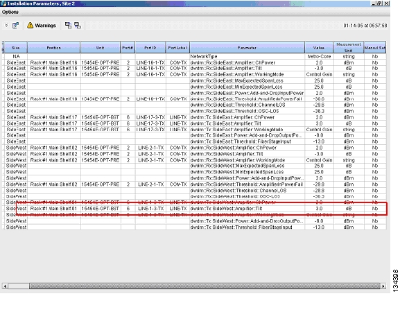
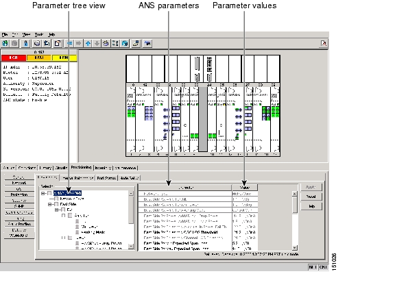
The proper tilt reference value is calculated by Cisco MetroPlanner and inserted in the Installation Parameter List imported during the node turn-up process (see the "Turn Up a Node" chapter in the Cisco ONS 15454 DWDM Procedure Guide). For both OPT-PRE and OPT-BST cards, the provisionable gain tilt reference range is between -3 dB and +3 dB.
During the automatic node setup (ANS) procedure, the tilt value for the OPT-BST or OPT-PRE card is provisioned by the TCC2/TCC2P card (see Figure 6-12). The provisioned tilt reference value is reported in the CTC OPT-PRE or OPT-BST card view (in the Provisioning > Opt. Ampli. Line > Parameters > Tilt Reference tab).
Figure 6-12 Cisco MetroPlanner Installation Parameters
6.6.2.2 System Gain Tilt Compensation With ROADM Nodes
When an ROADM node is present in the network, as shown in Figure 6-13, a per-channel dynamic gain equalization can be performed. Both gain tilt and gain ripple are completely compensated using the following techniques:
•
•
Figure 6-13 System Tilt Compensation With an ROADM Node
6.7 Automatic Node Setup
ANS is a TCC2/TCC2P function that adjusts values of the variable optical attenuators (VOAs) on the DWDM channel paths to equalize the per-channel power at the amplifier input. This power equalization means that at launch, all the channels have the same amplifier power level, independent from the input signal on the client interface and independent from the path crossed by the signal inside the node. This equalization is needed for two reasons:
•
•
To support ANS, the integrated VOAs and photodiodes are provided in the following ONS 15454 DWDM cards:
•
•
•
•
•
•
Optical power is equalized by regulating the VOAs. Based on the expected per-channel power, ANS automatically calculates the VOA values by:
•
•
VOAs operate in one of three working modes:
•
•
–
–
–
•
In the normal operating mode, OADM band card VOAs are set to a constant attenuation, while OADM channel card VOAs are set to a constant power. ANS requires the following VOA provisioning parameters to be specified:
•
•
To allow you to modify ANS values based on your DWDM deployment, provisioning parameters are divided into two contributions:
•
•
The ANS equalization algorithm requires the following knowledge of the DWDM transmission element layout:
•
•
•
ANS assumes that every DWDM port has a line direction parameter that is either west to east (W-E) or east to west (E-W). ANS automatically configures the mandatory optical connections according to following main rules:
•
•
•
•
•
•
Optical patchcords are passive devices that are not autodiscovered by ANS. However, optical patchcords are used to build the alarm correlation graph. From CTC or TL1 you can:
•
•
•
•
•
After you launch ANS, one of the following statuses is provided for each ANS parameter:
•
•
•
•
•
Optical connections are identified by the two termination points, each with an assigned slot and port. ANS checks that a new connection is feasible (according to embedded connection rules) and returns a denied message in the case of a violation.
ANS requires provisioning of the expected wavelength. When provisioning the expected wavelength, the following rules apply:
•
•
•
•
6.7.1 Automatic Node Setup Parameters
All ONS 15454 ANS parameters are calculated by Cisco MetroPlanner for nodes configured for metro core networks. (Parameters must be configured manually for metro access nodes.) Cisco MetroPlanner exports the calculated parameters to an ASCII file called NE Update. In CTC, you can import the NE Update file to automatically provision the node. Table 6-3 shows ANS parameters arranged in east and west, transmit and receive groups.
6.7.2 View and Provision ANS Parameters
All ANS parameters can be viewed and provisioned from the node view Provisioning > WDM-ANS > Provisioning tab, shown in Figure 6-14. The WDM-ANS > Provisioning > Provisioning tab presents the parameters in the following tree view:
root
+/- East
+/- Receiving
+/- Amplifier
+/- Power
+/- Threshold
+/- Transmitting
+/- Amplifier
+/- Power
+/- Threshold
+/- West
+/- Receiving
+/- Amplifier
+/- Power
+/- Threshold
+/- Transmitting
+/- Amplifier
+/- Power
+/- Threshold
Figure 6-14 WDM-ANS Provisioning
Table 6-4 shows the available parameters based on platform, line direction, and functional group.
The ANS parameters that appear in the WDM-ANS > Provisioning tab depend on the node type. Table 6-5 shows the DWDN node types and their ANS parameters.
Table 6-6 shows the following information for each ONS 15454 ANS parameter:
•
•
•
•
•
•
![]()
![]()
![]()
![]()
![]()
![]()
![]()
![]()
Posted: Tue Sep 18 06:05:08 PDT 2007
All contents are Copyright © 1992--2007 Cisco Systems, Inc. All rights reserved.
Important Notices and Privacy Statement.