|
|

Table Of Contents
1.2 Troubleshooting MXP or TXP Circuit Paths With Loopbacks
1.2.1 Perform a Facility Loopback on a Source-Node MXP or TXP Port
1.2.2 Perform a Terminal Loopback on a Source-Node MXP or TXP Port
1.2.3 Create a Facility Loopback on an Intermediate-Node MXP or TXP Port
1.2.4 Create a Terminal Loopback on Intermediate-Node MXP or TXP Ports
1.2.5 Perform a Facility Loopback on a Destination-Node MXP or TXP Port
1.2.6 Perform a Terminal Loopback on a Destination-Node MXP or TXP Port
1.3 Troubleshooting DWDM Circuit Paths With ITU-T G.709 Monitoring
1.3.1 ITU-T G.709 Monitoring in Optical Transport Networks
1.3.3 Optical Multiplex Section Layer
1.3.4 Optical Transmission Section Layer
1.3.5 Performance Monitoring Counters and Threshold Crossing Alerts
1.3.6 Forward Error Correction
1.3.7 Sample Trouble Resolutions
1.4.2 Retrieve Diagnostics File Button
1.4.3 Data Communications Network Tool
1.5 Restoring the Database and Default Settings
1.5.1 Restore the Node Database
1.6 PC Connectivity Troubleshooting
1.6.1 PC System Minimum Requirements
1.6.2 Sun System Minimum Requirements
1.6.3 Supported Platforms, Browsers, and JREs
1.6.4 Unsupported Platforms and Browsers
1.6.5 Unable to Verify the IP Configuration of Your PC
1.6.6 Browser Login Does Not Launch Java
1.6.7 Unable to Verify the NIC Connection on Your PC
1.6.8 Verify PC Connection to the ONS 15454 (ping)
1.6.9 The IP Address of the Node is Unknown
1.7 CTC Operation Troubleshooting
1.7.1 CTC Colors Do Not Appear Correctly on a UNIX Workstation
1.7.2 Unable to Launch CTC Help After Removing Netscape
1.7.3 Unable to Change Node View to Network View
1.7.4 Browser Stalls When Downloading CTC JAR Files From TCC2/TCC2P Card
1.7.6 Slow CTC Operation or Login Problems
1.7.7 Node Icon is Gray on CTC Network View
1.7.8 Java Runtime Environment Incompatible
1.7.9 Different CTC Releases Do Not Recognize Each Other
1.7.10 Username or Password Do Not Match
1.7.12 "Path in Use" Error When Creating a Circuit
1.7.13 Calculate and Design IP Subnets
1.8.1 ONS 15454 Switches Timing Reference
1.8.2 Holdover Synchronization Alarm
1.8.3 Free-Running Synchronization Mode
1.8.4 Daisy-Chained BITS Not Functioning
1.8.5 Blinking STAT LED after Installing a Card
1.9.1 Bit Errors Appear for a Traffic Card
1.9.2 Faulty Fiber-Optic Connections
1.11 Power Up Problems for Node and Cards
1.12 Network Level (Internode) Problems
1.12.2 System Restart after a Fiber Cut
1.12.3 OCHNC Circuits Creation Failure
1.13 Node Level (Intranode) Problems
General Troubleshooting
This chapter provides procedures for troubleshooting the most common problems encountered when operating a Cisco ONS 15454 DWDM shelf in ANSI or ETSI platforms. To troubleshoot specific alarms, see Chapter 2, "Alarm Troubleshooting." If you cannot find what you are looking for, contact Cisco Technical Support (1 800 553-2447).
Note
In this chapter, "ONS 15454" refers to both ANSI and ETSI versions of the platform unless otherwise noted.
This chapter includes the following sections on network problems:
Note
•
•
•
The remaining sections describe symptoms, problems, and solutions that are categorized according to the following topics:
•
•
•
•
•
•
•
•
•
•
1.1 Loopback Description
Use loopbacks and hairpin circuits to test newly created circuits before running live traffic or to logically locate the source of a network failure. All ONS 15454 and ONS 15454 SDH TXP and MXP cards allow loopbacks and hairpin test circuits. Other cards do not allow loopbacks, including OPT-BST, OPT-PRE, OSC-CSM, AD-xB-xx.x, and AD-xC-xx.x cards.
To create a loopback on an ANSI or SONET port, the port must be in the Out-of-Service and Management, Maintenance (OOS-MA,MT) service state. After you create the loopback, the service state becomes Out-of-Service and Management, Loopback and Maintenance (OOS-MA,LPBK & MT).
To create a loopback on an SDH or ETSI port, the port must be in the Locked, maintenance administrative state and the Locked-Enabled, loopback & maintenance administrative state.
Caution
Note
1.1.1 Facility Loopbacks
The following sections give general information about facility loopback operations and specific information about ONS 15454 or ONS 15454 SDH card loopback activity.
1.1.1.1 General Behavior
A facility loopback tests the line interface unit (LIU) of a card, the electrical interface assembly (EIA), and related cabling. After applying a facility loopback on a port, use a test set to run traffic over the loopback. A successful facility loopback isolates the LIU, the EIA, or the cabling plant as the potential cause of a network problem.
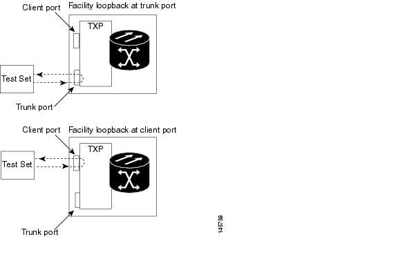
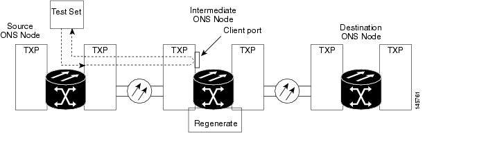
To test a card LIU, connect an optical test set to a trunk or client port and perform a facility loopback. Alternately, use a loopback or hairpin circuit on a card that is farther along the circuit path. For example, Figure 1-1 shows a facility loopback at a trunk port and at a client port on a TXP card.
Figure 1-1 Facility Loopback Path on a Near-End Transponder Card
Caution
Caution
1.1.1.2 Card Behavior
Port loopbacks either terminate or bridge the loopback signal. All MXP and TXP facility loopbacks are terminated as shown in Table 1-1.
When a port terminates a facility loopback signal, the signal only loops back to the originating port and is not transmitted downstream. When a port bridges a loopback signal, the signal loops back to the originating port and is also transmitted downstream.
Note
The loopback itself is listed in the Conditions window. For example, the window would list the LPBKFACILITY condition for a tested port. (The Alarms window would show the AS-MT condition which means that alarms are suppressed on the facility during loopback.)
With a client-side SONET or ANSI facility loopback, the client port service state is OOS-MA,LPBK & MT. However, any remaining client and trunk ports can be in any other service state. For SONET or ANSI cards in a trunk-side facility loopback, the trunk port service state is OOS-MA,LPBK & MT and the remaining client and trunk ports can be in any other service state.
With a client-side SDH or ESTI facility loopback, the client port is in the Locked-enabled,maintenance & loopback service state. However, the remaining client and trunk ports can be in any other service state. For MXP and TXP cards in a SDH or ETSI trunk-side facility loopback, the trunk port is in the Locked-enabled,maintenance & loopback service state and the remaining client and trunk ports can be in any other service state.
1.1.2 Terminal Loopbacks
The following sections give general information about terminal loopback operations and specific information about ONS 15454 card loopback activity.
1.1.2.1 General Behavior
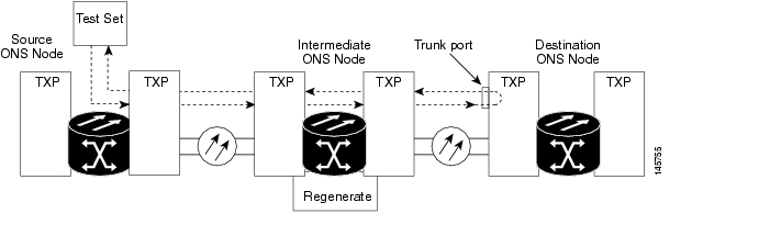
A terminal loopback tests a circuit path as it passes through a TXP or MXP card and loops back. For example, as shown in Figure 1-2, there are two types of terminal loopbacks shown for a TXP card.
The first is a terminal loopback at the client port. In this situation, the test set traffic comes in through the TXP trunk port, travels through the card, and turns around because of the terminal loopback in effect on the card just before it reaches the LIU of the client port. The signal is then sent back through the card to the trunk port and back to the test set.
The second is a terminal loopback at the trunk port. In this situation, the test set traffic comes in through the TXP client port, travels through the card, and turns around because of the terminal loopback in effect on the card just before it reaches the LIU of the trunk port. The signal is then sent back through the card to the client port and back to the test set.
This test verifies that the terminal circuit paths are valid, but does not test the LIU on the TXP card.
Figure 1-2 Terminal Loopback on a TXP Card
1.1.2.2 Card Behavior
ONS 15454 and ONS 15454 SDH terminal port loopbacks can either terminate or bridge the signal. TXP terminal loopbacks are terminated as shown in Table 1-2. During terminal loopbacks, if a port terminates a terminal loopback signal, the signal only loops back to the originating port and is not transmitted downstream. If the port bridges a loopback signal, the signal loops back to the originating port and is also transmitted downstream. Client card terminal loopback bridging and terminating behaviors are listed in Table 1-2.
Note
The MXP and TXP trunk and client ports can simultaneously maintain different service states:
•
•
•
•
•
•
The loopback itself is listed in the Conditions window. For example, the window would list the LPBKTERMINAL condition or LPBKFACILITY condition for a tested port. (The Alarms window would show the AS-MT condition, which indicates that all alarms are suppressed on the port during loopback testing.)
1.2 Troubleshooting MXP or TXP Circuit Paths With Loopbacks
Facility loopbacks and terminal loopbacks are often used together to test the circuit path through the network or to logically isolate a fault. Performing a loopback test at each point along the circuit path systematically isolates possible points of failure. MXP or TXP loopback tests differ from other testing in that loopback testing does not require circuit creation. MXP or TXP client ports are statically mapped to the trunk ports so no signal needs to traverse the cross-connect card (in a circuit) to test the loopback.
You can use these procedures on transponder cards (TXP, TXPP) or muxponder cards (MXP, MXPP) cards. The example in this section tests an MXP or TXP circuit on a three-node bidirectional line switched ring (BLSR) or multiplex section-shared protection ring (MS-SPRing). Using a series of facility loopbacks and terminal loopbacks, the example scenario traces the circuit path, tests the possible failure points, and eliminates them. The logical progression contains six network test procedures:
Note
Note
1.
2.
3.
4.
5.
6.
Note
1.2.1 Perform a Facility Loopback on a Source-Node MXP or TXP Port
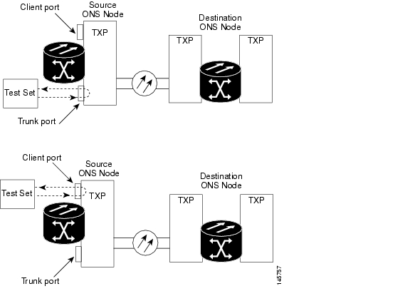
This facility loopback test is performed on the node source port in the network circuit. In the testing situation used in this example, the source muxponder or transponder port under test is located in the source node. Facility loopback can be performed at the trunk port or at a client port. Completing a successful facility loopback on this port isolates the source MXP or TXP port as a possible failure point. Figure 1-3 shows the facility loopback examples on source ONS node TXP ports (client and trunk).
Figure 1-3 Facility Loopback on a Circuit Source MXP or TXP Port
Caution
Note
Complete the "Create the Facility Loopback on the Source-Node MXP or TXP Port" procedure.
Create the Facility Loopback on the Source-Node MXP or TXP Port
Step 1
Note
Use appropriate cabling to attach the transmit (Tx) and receive (Rx) terminals of the optical test set to the port you are testing. The Tx and Rx terminals connect to the same port.
Step 2
Step 3
Step 4
Step 5
Step 6
Step 7
Step 8
Note
Step 9
Test and Clear the MXP or TXP Facility Loopback Circuit
Step 1
Step 2
Step 3
a.
b.
c.
d.
e.
Step 4
Test the MXP or TXP Card
Step 1
Warning
Caution
Step 2
Step 3
Step 4
Step 5
a.
b.
c.
d.
e.
Step 6
1.2.2 Perform a Terminal Loopback on a Source-Node MXP or TXP Port
The terminal loopback test is performed on the node source MXP or TXP muxponder or transponder port. For the circuit in this example, it is the source TXP trunk port or a client port in the source node. Completing a successful terminal loopback to a node source port verifies that the circuit is through the source port. Figure 1-4 shows an example of a terminal loopback on a source TXP port and a client TXP port.
Figure 1-4 Terminal Loopback on a Source-Node MXP or TXP Port
Caution
Note
Complete the "Create the Terminal Loopback on a Source-Node MXP or TXP Port" procedure.
Create the Terminal Loopback on a Source-Node MXP or TXP Port
Step 1
Note
a.
b.
Step 2
Step 3
Step 4
Step 5
Step 6
Step 7
Step 8
Step 9
Test and Clear the MXP or TXP Port Terminal Loopback Circuit
Step 1
Step 2
Step 3
a.
b.
c.
d.
e.
f.
Step 4
Test the MXP or TXP Card
Step 1
Warning
Caution
Step 2
Step 3
Step 4
Step 5
a.
b.
c.
d.
e.
f.
Step 6
1.2.3 Create a Facility Loopback on an Intermediate-Node MXP or TXP Port
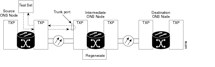
Performing the facility loopback test on an intermediate port isolates whether this node is causing circuit failure. In the situation shown in Figure 1-5, the test is being performed on an intermediate MXP or TXP port.
Figure 1-5 Facility Loopback on an Intermediate-Node MXP or TXP Port
Caution
Note
Complete the "Create a Facility Loopback on an Intermediate-Node MXP or TXP Port" procedure.
Create a Facility Loopback on an Intermediate-Node MXP or TXP Port
Step 1
Note
a.
b.
Step 2
Step 3
Step 4
Step 5
Step 6
Step 7
Step 8
Step 9
Test and Clear the MXP or TXP Port Facility Loopback Circuit
Step 1
Step 2
Step 3
a.
b.
c.
d.
e.
Step 4
Test the MXP or TXP Card
Step 1
Warning
Caution
Step 2
Step 3
Step 4
Step 5
a.
b.
c.
d.
e.
Step 6
1.2.4 Create a Terminal Loopback on Intermediate-Node MXP or TXP Ports
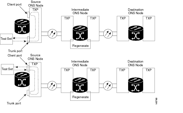
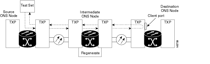
In the next troubleshooting test, you perform a terminal loopback on the intermediate-node port to isolate whether the intermediate client or trunk port is causing circuit trouble. In the example situation in Figure 1-6, the terminal loopback is performed on an intermediate MXP or TXP port in the circuit. If you successfully complete a terminal loopback on the node, this node is excluded from possible sources of circuit trouble.
Figure 1-6 Terminal Loopback on an Intermediate-Node MXP or TXP Port
Caution
Note
Complete the "Create a Terminal Loopback on Intermediate-Node MXP or TXP Ports" procedure.
Create a Terminal Loopback on Intermediate-Node MXP or TXP Ports
Step 1
Note
a.
b.
Step 2
Step 3
a.
•
•
b.
c.
d.
e.
f.
g.
Step 4
Test and Clear the MXP or TXP Terminal Loopback Circuit
Step 1
Step 2
Step 3
a.
b.
c.
d.
e.
f.
Step 4
Test the MXP or TXP Card
Step 1
Warning
Caution
Step 2
Step 3
Step 4
Step 5
a.
b.
c.
d.
e.
f.
Step 6
1.2.5 Perform a Facility Loopback on a Destination-Node MXP or TXP Port
You perform a facility loopback test at the destination port to determine whether this local port is the source of circuit trouble. The example in Figure 1-7 shows a facility loopback being performed on a TXP client or trunk port at a destination node.
Figure 1-7 Facility Loopback on a Destination-Node MXP or TXP Port
Caution
Note
Complete the "Create the Facility Loopback on a Destination-Node MXP or TXP Port" procedure.
Create the Facility Loopback on a Destination-Node MXP or TXP Port
Step 1
Note
a.
b.
Step 2
Step 3
a.
•
•
b.
c.
d.
e.
f.
g.
Step 4
Test and Clear the MXP or TXP Facility Loopback Circuit
Step 1
Step 2
Step 3
a.
b.
c.
d.
e.
Step 4
Test the MXP or TXP Card
Step 1
Warning
Caution
Step 2
Step 3
Step 4
Step 5
a.
b.
c.
d.
e.
Step 6
1.2.6 Perform a Terminal Loopback on a Destination-Node MXP or TXP Port
The terminal loopback at the destination-node port is the final local hardware error elimination in the circuit troubleshooting process. If this test is completed successfully, you have verified that the circuit is good up to the destination port. The example in Figure 1-8 shows a terminal loopback on an destination node TXP port.
Figure 1-8 Terminal Loopback on a Destination-Node MXP or TXP Port
Caution
Note
Complete the "Create the Terminal Loopback on a Destination-Node MXP or TXP Port" procedure.
Create the Terminal Loopback on a Destination-Node MXP or TXP Port
Step 1
Note
a.
b.
Step 2
Note
Step 3
a.
•
•
b.
c.
d.
e.
f.
g.
Step 4
Test and Clear the MXP or TXP Terminal Loopback Circuit
Step 1
Step 2
Step 3
a.
b.
c.
d.
e.
f.
Step 4
Step 5
Test the MXP or TXP Card
Step 1
Warning
Caution
Step 2
Step 3
Step 4
Step 5
a.
b.
c.
d.
e.
f.
The entire circuit path has now passed its comprehensive series of loopback tests. This circuit qualifies to carry live traffic.
1.3 Troubleshooting DWDM Circuit Paths With ITU-T G.709 Monitoring
This section provides an overview of the optical transport network (OTN) specified in ITU-T G.709, Network Node Interface for the Optical Transport Network, and provides troubleshooting procedures for DWDM circuit paths in the ITU-T G.709 OTN using PM and TCAs.
1.3.1 ITU-T G.709 Monitoring in Optical Transport Networks
ITU-T Recommendation G.709 is part of a suite of recommendations covering the full functionality of an OTN. ITU-T G.709 enables single-wavelength SONET transparent optical wavelength-based networks. ITU-T G.709 adds the Operation, Administration, Maintenance, and Provisioning (OAM&P) functionality of SONET/SDH to DWDM optical networks. It adds extra overhead to existing SONET, Ethernet, or asynchronous transfer mode (ATM) bit streams for performance management and improvement.
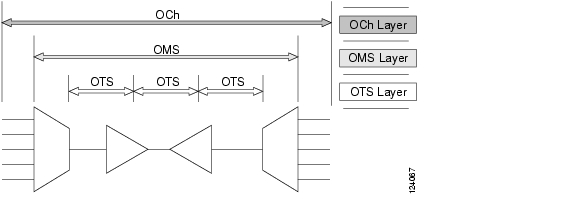
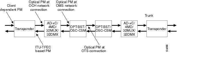
Like traditional SONET networks, ITU-T G.709 optical networks have a layered design ( Figure 1-9). This structure enables localized monitoring that helps you isolate and troubleshoot network problems.
Figure 1-9 Optical Transport Network Layers
1.3.2 Optical Channel Layer
The optical channel (OCH) layer is the outermost part of the OTN and spans from client to client. The optical channel is built as follows:
1.
2.
3.
4.
1.3.3 Optical Multiplex Section Layer
The optical multiplex section (OMS) of the OTN allows carriers to identify errors occurring within DWDM network sections. The OMS layer consists of a payload and an overhead (OMS-OH). It supports the ability to monitor multiplexed sections of the network, for example, the span between an optical multiplexer such as the 32MUX-O card and an optical demultiplexer such as the 32DMX-O card.
1.3.4 Optical Transmission Section Layer
The optical transmission section (OTS) layer supports monitoring partial spans of a network's multiplexed sections. This layer consists of a payload and an overhead (OTS-OH). It is a transmission span between two elements in an optical network, such as between:
•
•
•
1.3.5 Performance Monitoring Counters and Threshold Crossing Alerts
PM counters and TCAs can be used for identifying trouble and troubleshooting problems in ITU-T G.709 optical transport networks. ITU-T Recommendation M.2401 recommends that the following PM parameters be monitored at the ODUk layer:
•
•
Different PM count parameters are associated with different read points in a network. Figure 1-10 illustrates the PM read points that are useful in identifying DWDM circuit points of failure. The "Performance Monitoring" chapter in the Cisco ONS 15454 DWDM Reference Manual lists all PM parameters and provides block diagrams of signal entry points, exit points, and interconnections between the individual circuit cards. Consult these specifications to determine which PM parameters are associated with the system points you want to monitor or provision with CTC or TL1. The monitoring points might vary according to your configuration.
Note
Figure 1-10 Performance Monitoring Points on ONS DWDM
TCAs are used to monitor performance through the management interface by indicating whether preset thresholds have been crossed, or whether a transmission (such as a laser transmission) is degraded. TCAs are not associated with severity levels. They are usually associated with rate, counter, and percentage parameters that are available at transponder monitoring points. The "Performance Monitoring" chapter in the Cisco ONS 15454 DWDM Reference Manual contains more information about these alerts.
Select and complete the following procedures according to your network parameters.
Set Node Default BBE or SES Card Thresholds
Complete the following procedure to provision default node ODUk BBE and SES PM thresholds for TXP cards.
Step 1
Figure 1-11 Set Default BBE/SES Card Thresholds
Step 2
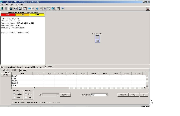
Provision Individual Card BBE or SES Thresholds in CTC
Complete the following procedure to provision BBE or SES PM thresholds in CTC for an individual TXP card.
Step 1
Step 2
Figure 1-12 Provision Card BBE/SES Thresholds
Step 3
Step 4
Step 5
Step 6
Provision Card PM Thresholds Using TL1
Complete the following procedure if you wish to provision PM thresholds in TL1 rather than in CTC.
Step 1
Step 2
SET-TH-OCH:[<TID>]:<AID>:<CTAG>::<MONTYPE>,<THLEV>,[<LOCN>],,[<TMPER>];
where:
•
•
•
•
•
Note
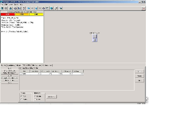
Provision Optical TCA Thresholds
Complete the following procedure to provision TCA thresholds in CTC.
Step 1
Figure 1-13 Provision Optical TCA Thresholds
Step 2
Step 3
Step 4
1.3.6 Forward Error Correction
In DWDM spans, FEC reduces the quantities of retiming, reshaping, and regeneration (3R) needed to maintain signal quality. The following two PM parameters are associated with FEC:
•
•
Complete the following procedure to provision BIEC and UNC-WORDS PM parameters for FEC.
Provision Card FEC Thresholds
Step 1
Step 2
Figure 1-14 Provision Card FEC Thresholds
Step 3
Step 4
Step 5
1.3.7 Sample Trouble Resolutions
The following sample trouble resolutions use PM and TCAs to isolate degrade points.
Symptom There is a BBE TCA on a single transponder pair.
Possible Cause The transponder input power is out of range.
Recommended Action Check the input power on the transponder. It should be within the specified/supported range.
Possible Cause There are dirty trunk connectors on the transponder.
Recommended Action Check the connector on the trunk port.
Possible Cause There is a degraded trunk patchcord between the transponder and the DWDM port.
Recommended Action Check the patchcord on the transponder DWDM port.
Possible Cause There are dirty client connectors on the ADxC-xx.x card transmit port or the demultiplexer (DMX) has crossed the near-end TCA.
Recommended Action Check the connector on the OCH port of the ADxC-xx.x card.
Possible Cause There are dirty client connectors on the ADxC-xx.x card receive port or the multiplexer (MUX) has crossed the far-end TCA point.
Recommended Action If an optical channel bypass exists along the line, check the connectors.
Symptom There is a BBE TCA on all transponders connected to an ADxB-xx.x card.
Possible Cause The transponder input power is out of range.
Recommended Action Check the input power on the transponder. It should be within the specified/supported range.
Possible Cause There is a dirty connector on the 4MD-xx.x card port.
Recommended Action Check the connector on the drop port of the 4MD-xx.x card.
Possible Cause There is a dirty connector on the ADxB-xx.x card drop port, and it has crossed the near-end TCA point.
Recommended Action Check the connector on the drop port of the ADxB-xx.x card.
Possible Cause There is a dirty connector on the ADxB-xx.x card add port and it has crossed the far-end TCA.
Recommended Action Check the patchcord on the 4MD-xx.x or AD1B-xx.x card.
Possible Cause There is a degraded patchcord between the ADxB-xx.x and 4MD-xx.x cards.
Recommended Action If an optical band bypass exists along the line, check the band connectors.
Symptom There is a BBE TCA on all transponders that the OCH passes through a single OTS section.
Possible Cause This is not a transponder or channel-related issue.
Recommended Action The problem is in the intercabinet signal path preceding the transponder. Refer to the Cisco ONS 15454 DWDM Procedure Guide for more information about configurations and acceptance tests for this area.
Symptom You have a laser bias current (LBC) TCA on a single transponder.
Possible Cause The laser of the transponder is degrading.
Recommended Action The problem is within the laser circuitry. Check the OPT-PRE or OPT-BST optical amplifier cards. Refer to the Cisco ONS 15454 DWDM Procedure Guide for more information about setting up these cards.
1.4 Using CTC Diagnostics
In Software Release 7.0, CTC provides diagnostics for the following functions:
•
•
•
•
•
•
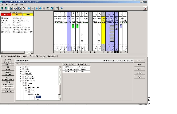
Some of these functions, such as ASIC verification and standby card operation, are invisibly monitored in background functions. Change or problem notifications are provided in the Alarms and Conditions windows. Other diagnostic functions—verifying card LED function, creating bidirectional diagnostic circuits, and also downloading diagnostic files for technical support—are available to the user in the node view (single-shelf mode) or shelf view (multishelf mode) Maintenance > Diagnostic tab. The user-operated diagnostic features are described in the following paragraphs.
1.4.1 Card LED Lamp Tests
A card LED lamp test determines whether card-level indication LEDs are operational. This diagnostic test is run as part of the initial ONS 15454 turn-up, during maintenance routines, or any time you question whether an LED is in working order. Maintenance or higher-level users can complete the following tasks to verify LED operation.
Verify Card LED Operation
Step 1
Figure 1-15 ONS 15454 Node View Diagnostic Window
Step 2
Step 3
•
•
•
Step 4
1.4.2 Retrieve Diagnostics File Button
When you click the Retrieve Diagnostics File button in the Maintenance window, CTC retrieves system data that can be off-loaded by a Maintenance or higher-level user to a local directory and sent to Technical Support for troubleshooting purposes. The diagnostics file is in machine language and is not human-readable, but can be used by Cisco Technical Support for problem analysis. Complete the following task to off-load the diagnostics file.
Note
Off-Load the Diagnostics File
Step 1
Step 2
Step 3
Step 4
You do not have to give the archive file a particular extension. It is a compressed file (gzip) that can be unzipped and read by Cisco Technical Support.
Step 5
The Get Diagnostics status window shows a progress bar indicating the percentage of the file being saved, then shows "Get Diagnostics Complete."
Step 6
1.4.3 Data Communications Network Tool
CTC contains a data communications network (DCN) tool that assists with network troubleshooting for Open Shortest Path First (OSPF) networks. This tool, located in network view, is shown in Figure 1-16. It executes an internal dump command to retrieve information about all nodes accessible from the entry point.
Figure 1-16 DCN Tools OSPF Dump
The dump, which provides the same information as a dump executed by special networking commands, is available at the network view in the Maintenance > Diagnostic tab. You can select the access point node in the Select Node drop-down list. To create the dump, click Retrieve. (To clear the dump, click Clear.)
The contents of the dump file can be saved or printed and furnished to Cisco Technical Support for use in OSPF network support.
1.5 Restoring the Database and Default Settings
This section contains troubleshooting for node operation errors that require restoration of software data or the default node setup.
1.5.1 Restore the Node Database
Symptom One or more nodes do not function properly or have incorrect data.
Possible Cause Incorrect or corrupted node database.
Recommended Action Complete the procedures in the "Maintain the Node" chapter of the Cisco ONS 15454 DWDM Procedure Guide.
1.6 PC Connectivity Troubleshooting
This section contains information about system minimum requirements, supported platforms, browsers, and Java Runtime Environments (JREs) for Software R7.0, and troubleshooting procedures for PC and network connectivity to the ONS 15454.
1.6.1 PC System Minimum Requirements
Workstations running CTC Software R7.0 for the Optical Networking System (ONS) products on Windows platforms need to have the following minimum requirements:
•
•
•
•
•
1.6.2 Sun System Minimum Requirements
Workstations running Software R7.0 for the ONS products on Sun workstations need to have the following minimum requirements:
•
•
•
1.6.3 Supported Platforms, Browsers, and JREs
Software R7.0 supports the following platforms:
•
•
•
•
•
•
Software R7.0 supports the following browsers and JREs:
•
•
•
•
Note
•
•
•
Note
1.6.4 Unsupported Platforms and Browsers
Software R7.0 does not support the following platforms:
•
•
•
Software R7.0 does not support the following browsers and JREs:
•
•
•
1.6.5 Unable to Verify the IP Configuration of Your PC
Symptom When connecting your PC to the ONS 15454, you are unable to successfully ping the IP address of your PC to verify the IP configuration.
Possible Cause The IP address was entered incorrectly.
Recommended Action Verify that the IP address used to ping the PC matches the IP address displayed when in the Windows IP Configuration information retrieved from the system. See the "Verify the IP Configuration of Your PC" procedure.
Possible Cause The IP configuration of your PC is not properly set.
Recommended Action Verify the IP configuration of your PC. Complete the "Verify the IP Configuration of Your PC" procedure. If this procedure is unsuccessful, contact your network administrator for instructions to correct the IP configuration of your PC.
Verify the IP Configuration of Your PC
Step 1
Step 2
Step 3
The Windows IP configuration information appears, including the IP address, the subnet mask, and the default gateway.
Note
Step 4
Step 5
If the DOS window returns multiple (usually four) replies, the IP configuration is working properly.
If you do not receive a reply, your IP configuration might not be properly set. Contact your network administrator for instructions to correct the IP configuration of your PC.
1.6.6 Browser Login Does Not Launch Java
Symptom The message "Loading Java Applet" does not appear and the JRE does not launch during the initial login.
Possible Cause The PC operating system and browser are not properly configured.
Recommended Action Reconfigure the PC operating system Java Plug-in Control Panel and the browser settings. Complete the "Reconfigure the PC Operating System Java Plug-in Control Panel" procedure and the "Reconfigure the Browser" procedure.
Reconfigure the PC Operating System Java Plug-in Control Panel
Step 1
Step 2
a.
b.
c.
d.
Step 3
Step 4
Step 5
Step 6
Step 7
Step 8
Step 9
Reconfigure the Browser
Step 1
Step 2
a.
b.
c.
d.
e.
f.
•
•
g.
h.
i.
Step 3
a.
b.
c.
d.
Step 4
Step 5
Step 6
1.6.7 Unable to Verify the NIC Connection on Your PC
Symptom When connecting your PC to the ONS 15454, you are unable to verify that the NIC connection is working properly because the link LED is not illuminated or flashing.
Possible Cause The CAT-5 cable is not plugged in properly.
Recommended Action Confirm that both ends of the cable are properly inserted. If the cable is not fully inserted due to a broken locking clip, the cable should be replaced.
Possible Cause The CAT-5 cable is damaged.
Recommended Action Ensure that the cable is in good condition. If in doubt, use a known-good cable. Often, cabling is damaged due to pulling or bending. (For information about installing cable, refer to the "Install Cards and Fiber-Optic Cable" chapter in the Cisco ONS 15454 DWDM Procedure Guide.)
Possible Cause Incorrect type of CAT-5 cable is being used.
Recommended Action If connecting an ONS 15454 directly to your laptop, a PC, or a router, use a straight-through CAT-5 cable. When connecting the ONS 15454 to a hub or a LAN switch, use a crossover CAT-5 cable. For details on the types of CAT-5 cables, see the "Crimp Replacement LAN Cables" section.
Possible Cause The NIC is improperly inserted or installed.
Recommended Action If you are using a Personal Computer Memory Card International Association (PCMCIA)-based NIC, remove and reinsert the NIC to make sure the NIC is fully inserted. (If the NIC is built into the laptop or PC, verify that the NIC is not faulty.)
Possible Cause The NIC is faulty.
Recommended Action Confirm that the NIC is working properly. If you have no issues connecting to the network (or any other node), then the NIC should be working correctly. If you have difficulty connecting a to the network (or any other node), then the NIC might be faulty and needs to be replaced.
1.6.8 Verify PC Connection to the ONS 15454 (ping)
Symptom The TCP/IP connection was established and then lost.
Possible Cause A lost connection between the PC and the ONS 15454.
Recommended Action Use a standard ping command to verify the TCP/IP connection between the PC and the ONS 15454 TCC2/TCC2P card. A ping command should work if the PC connects directly to the TCC2/TCC2P card or uses a LAN to access the TCC2/TCC2P card. Complete the "Ping the ONS 15454" procedure.
Ping the ONS 15454
Step 1
a.
b.
Step 2
ping ONS-15454-IP-address
For example:
ping 198.168.10.10
Step 3
Step 4
Step 5
Step 6
1.6.9 The IP Address of the Node is Unknown
Symptom The IP address of the node is unknown and you are unable to login.
Possible Cause The node is not set to the default IP address.
Recommended Action Leave one TCC2/TCC2P card in the shelf. Connect a PC directly to the remaining TCC2/TCC2P card and perform a hardware reset of the card. The TCC2/TCC2P card transmits the IP address after the reset to enable you to capture the IP address for login. Complete the "Retrieve Unknown Node IP Address" procedure.
Retrieve Unknown Node IP Address
Step 1
Step 2
Step 3
Step 4
1.7 CTC Operation Troubleshooting
This section contains troubleshooting procedures for CTC login or operation problems.
1.7.1 CTC Colors Do Not Appear Correctly on a UNIX Workstation
Symptom When running CTC on a UNIX workstation, the colors do not appear correctly. For example, both major and minor alarms appear in the same color.
Possible Cause When running in 256-color mode on a UNIX workstation, color-intensive applications such as Netscape might use all of the colors.
Recommended Action CTC requires a full 24-color palette to run properly. When logging into CTC on a UNIX workstation, run as many colors as your adapter will support. In addition, you can use the -install or the -ncols 32 command line options to limit the number of colors that Netscape uses. Complete the "Limit Netscape Colors" procedure. If the problem persists after limiting Netscape colors, exit any other color-intensive applications in use.
Limit Netscape Colors
Step 1
Step 2
•
•
1.7.2 Unable to Launch CTC Help After Removing Netscape
Symptom After removing Netscape and running CTC using Internet Explorer, you are unable to launch CTC Help and receive an "MSIE is not the default browser" error message.
Possible Cause Loss of association between browser and Help files.
Recommended Action When the CTC software and Netscape are installed, the Help files are associated with Netscape by default. When you remove Netscape, the Help files are not automatically associated with Internet Explorer as the default browser. Reset Internet Explorer as the default browser so that CTC associates the Help files to the correct browser. Complete the "Reset Internet Explorer as the Default Browser for CTC" procedure to associate the CTC Help files to the correct browser.
Reset Internet Explorer as the Default Browser for CTC
Step 1
Step 2
Step 3
Step 4
Step 5
Step 6
Step 7
1.7.3 Unable to Change Node View to Network View
Symptom When activating a large, multinode BLSR from Software R3.2 to Software R3.3, some of the nodes appear grayed out. Logging into the new CTC, the user is unable to change node view (single-shelf mode) or shelf view (multishelf mode) to network view on any nodes, from any workstation. This is accompanied by an "Exception occurred during event dispatching: java.lang.OutOfMemoryError" in the java window.
Possible Cause The large, multinode BLSR requires more memory for the graphical user interface (GUI) environment variables.
Recommended Action Set the system or user CTC_HEAP environment variable to increase the memory limits. Complete the "Set the CTC_HEAP and CTC_MAX_PERM_SIZE_HEAP Environment Variables for Windows" procedure or the "Set the CTC_HEAP and CTC_MAX_PERM_SIZE_HEAP Environment Variables for Solaris" procedure to enable the CTC_HEAP variable change.
Note
Set the CTC_HEAP and CTC_MAX_PERM_SIZE_HEAP Environment Variables for Windows
Note
Step 1
Step 2
Step 3
Step 4
Step 5
Step 6
CTC_HEAPin the Variable Name field.Step 7
512in the Variable Value field, and then click the OK button to create the variable.Step 8
Step 9
CTC_MAX_PERM_SIZE_HEAPin the Variable Name field.Step 10
128in the Variable Value field, and then click the OK button to create the variable.Step 11
Step 12
Set the CTC_HEAP and CTC_MAX_PERM_SIZE_HEAP Environment Variables for Solaris
Step 1
Step 2
Example
The following example shows how to set the environment variables in the C shell:
% setenv CTC_HEAP 512% setenv CTC_MAX_PERM_SIZE_HEAP 1281.7.4 Browser Stalls When Downloading CTC JAR Files From TCC2/TCC2P Card
Symptom The browser stalls or hangs when downloading a CTC Java archive (JAR) file from the TCC2/TCC2P card.
Possible Cause McAfee VirusScan software might be interfering with the operation. The problem occurs when the VirusScan Download Scan is enabled on McAfee VirusScan 4.5 or later.
Recommended Action Disable the VirusScan Download Scan feature. Complete the "Disable the VirusScan Download Scan" procedure.
Disable the VirusScan Download Scan
Step 1
Step 2
Step 3
Step 4
Step 5
Step 6
Step 7
Step 8
Step 9
1.7.5 CTC Does Not Launch
Symptom CTC does not launch; usually an error message appears before the login window appears.
Possible Cause The Netscape browser cache might point to an invalid directory.
Recommended Action Redirect the Netscape cache to a valid directory. Complete the "Redirect the Netscape Cache to a Valid Directory" procedure.
Redirect the Netscape Cache to a Valid Directory
Step 1
Step 2
Step 3
Step 4
Step 5
The cache file location is usually C:\ProgramFiles\Netscape\Users\yourname\cache. The yourname segment of the file location is often the same as the user name.
1.7.6 Slow CTC Operation or Login Problems
Symptom You experience slow CTC operation or have problems logging into CTC.
Table 1-3 describes the potential cause of the symptom and the solution.
Table 1-3 Slow CTC Operation or Login Problems
The CTC cache file might be corrupted or might need to be replaced.
Search for and delete cache files. This operation forces the ONS 15454 to download a new set of Java archive (JAR) files to your computer hard drive. Complete the "Delete the CTC Cache File Automatically" procedure or the "Delete the CTC Cache File Manually" procedure.
Insufficient heap memory allocation.
Increase the heap size if you are using CTC to manage more than 50 nodes concurrently. See the "Set the CTC_HEAP and CTC_MAX_PERM_SIZE_HEAP Environment Variables for Windows" procedure or the "Set the CTC_HEAP and CTC_MAX_PERM_SIZE_HEAP Environment Variables for Solaris" procedure.
Note
Delete the CTC Cache File Automatically
Caution
Step 1
Step 2
Step 3
Figure 1-17 Deleting the CTC Cache
Delete the CTC Cache File Manually
Caution
Step 1
Step 2
Step 3
Step 4
Step 5
1.7.7 Node Icon is Gray on CTC Network View
Symptom The CTC network view shows one or more node icons as gray in color and without a node name.
Possible Cause Different CTC releases do not recognize each other.
Recommended Action Correct the core version build as described in the "Different CTC Releases Do Not Recognize Each Other" section.
Possible Cause Username and password do not match.
Recommended Action Correct the username and password as described in the "Username or Password Do Not Match" section.
Possible Cause A lost DCC connection.
Recommended Action Usually accompanied by an embedded operations channel (EOC) alarm. Clear the EOC alarm and verify the DCC connection as described in the "EOC" alarm.
1.7.8 Java Runtime Environment Incompatible
Symptom The CTC application does not run properly.
Possible Cause The compatible Java 2 JRE is not installed.
Recommended Action The JRE contains the Java virtual machine, runtime class libraries, and Java application launcher that are necessary to run programs written in the Java programming language. The ONS 15454 CTC is a Java application. A Java application, unlike an applet, cannot rely completely on a web browser for installation and runtime services. When you run an application written in the Java programming language, you need the correct JRE installed. The correct JRE for each CTC software release is included on the Cisco ONS 15454 software CD. Complete the "Launch CTC to Correct the Core Version Build" procedure. If you are running multiple CTC software releases on a network, the JRE installed on the computer must be compatible with the different software releases. Table 1-4 shows JRE compatibility with ONS 15454 software releases.
Table 1-4 JRE Compatibility
ONS 15454 R2.2.1 and earlier
Yes
No
No
No
ONS 15454 R2.2.2
Yes
Yes
No
No
ONS 15454 R3.0
Yes
Yes
No
No
ONS 15454 R3.1
Yes
Yes
No
No
ONS 15454 R3.2
Yes
Yes
No
No
ONS 15454 R3.3
Yes
Yes
No
No
ONS 15454 R3.4
No
Yes
No
No
ONS 15454 R4.02
No
Yes
No
No
ONS 15454 R4.1
No
Yes
No
No
ONS 15454 R4.5
No
Yes
No
No
ONS 15454 R4.6
No
Yes
Yes
No
ONS 15454 R4.7
No
Yes
Yes
No
ONS 15454 R5.0
No
Yes
Yes
No
ONS 15454 R6.0
No
No
Yes
No
ONS 15454 R7.0
No
No
No
Yes
1 JRE 1.4.2 is the recommended version and is provided on the software CD.
2 Software Release 4.0 notifies you if an earlier JRE version is running on your PC or UNIX workstation.
Launch CTC to Correct the Core Version Build
Step 1
Step 2
Step 3
Step 4
1.7.9 Different CTC Releases Do Not Recognize Each Other
Symptom Different CTC releases do not recognize each other. This situation is often accompanied by the INCOMPATIBLE-SW alarm.
Possible Cause The software loaded on the connecting workstation and the software on the TCC2/TCC2P card are incompatible.
Recommended Action This occurs when the TCC2/TCC2P software is upgraded but the PC has not yet upgraded the compatible CTC JAR file. It also occurs on login nodes with compatible software that encounter other nodes in the network that have a newer software version. Complete the "Launch CTC to Correct the Core Version Build" procedure.
Note
Launch CTC to Correct the Core Version Build
Step 1
Step 2
Step 3
Step 4
1.7.10 Username or Password Do Not Match
Symptom A username/password mismatch often occurs concurrently with a NOT-AUTHENTICATED alarm.
Possible Cause The username or password entered does not match the information stored in the TCC2/TCC2P card.
Recommended Action All ONS nodes must have the same username and password created to display every ONS node in the network. You can also be locked out of certain ONS nodes on a network if your username and password were not created on those specific ONS nodes. For initial login to the ONS 15454, enter the CISCO15 user name in capital letters, click Login, and use the password otbu+1, which is case-sensitive.
Complete the "Verify Correct Username and Password" procedure. If the node has been configured for Remote Authentication Dial In User Service (RADIUS) authentication, the username and password are verified against the RADIUS server database rather than the security information in the local node database. For more information about RADIUS security, refer to the "Security Reference" chapter in the Cisco ONS 15454 DWDM Reference Manual.
Verify Correct Username and Password
Step 1
Step 2
Step 3
1.7.11 DCC Connection Lost
Symptom DCC connection is lost. The node usually has alarms and the nodes in the network view have a gray icon. This symptom is usually accompanied by an EOC alarm.
Possible Cause A lost DCC connection.
Recommended Action Usually accompanied by an EOC alarm. Clear the EOC alarm and verify the DCC connection as described in the "EOC" alarm.
1.7.12 "Path in Use" Error When Creating a Circuit
Symptom While creating a circuit, you get a "Path in Use" error that prevents you from completing the circuit creation.
Possible Cause Another user has already selected the same source port to create another circuit.
Recommended Action CTC does not remove a card or port from the available list until a circuit is completely provisioned. If two users simultaneously select the same source port to create a circuit, the first user to complete circuit provisioning gets use of the port. The other user gets the "Path in Use" error. Cancel the circuit creation and start over, or click Back until you return to the initial circuit creation window. The source port that was previously selected no longer appears in the available list because it is now part of a provisioned circuit. Select a different available port and begin the circuit creation process again.
1.7.13 Calculate and Design IP Subnets
Symptom You cannot calculate or design IP subnets on the ONS 15454.
Possible Cause The IP capabilities of the ONS 15454 require specific calculations to properly design IP subnets.
Recommended Action Cisco provides a free online tool to calculate and design IP subnets. Go to http://www.cisco.com/techtools/ip_addr.html. For information about ONS 15454 IP capability, refer to the "Management Network Connectivity" chapter in the Cisco ONS 15454 DWDM Reference Manual.
1.8 Timing
This section provides solutions to common timing reference errors and alarms.
1.8.1 ONS 15454 Switches Timing Reference
Symptom Timing references switch when one or more problems occur.
Possible Cause The optical or building integrated timing supply (BITS) input is receiving loss of signal (LOS), loss of frame (LOF), or AIS alarms from its timing source.
Possible Cause The optical or BITS input is not functioning.
Possible Cause The synchronization status messaging (SSM) message is set to do not use for synchronization (DUS).
Possible Cause SSM indicates a Stratum 3 or lower clock quality.
Possible Cause The input frequency is off by more than 15 ppm.
Possible Cause The input clock wanders and has more than three slips in 30 seconds.
Possible Cause A bad timing reference existed for at least two minutes.
Recommended Action The ONS 15454 internal clock operates at a Stratum 3E level of accuracy. This gives the ONS 15454 a free-running synchronization accuracy of +/- 4.6 ppm and a holdover stability of less than 255 slips in the first 24 hours or 3.7 x 10⁻⁷/day, including temperature. ONS 15454 free-running synchronization relies on the Stratum 3 internal clock. Over an extended time period, using a higher quality Stratum 1 or Stratum 2 timing source results in fewer timing slips than a lower quality Stratum 3 timing source.
1.8.2 Holdover Synchronization Alarm
Symptom The clock is running at a different frequency than normal and the "HLDOVRSYNC" alarm appears.
Possible Cause The last reference input has failed.
Recommended Action The clock is running at the frequency of the last known-good reference input. This alarm is raised when the last reference input fails. See the "HLDOVRSYNC" alarm on page 2-65 for a detailed description.
Note
1.8.3 Free-Running Synchronization Mode
Symptom The clock is running at a different frequency than normal and the "FRNGSYNC" alarm appears.
Possible Cause No reliable reference input is available.
Recommended Action The clock is using the internal oscillator as its only frequency reference. This occurs when no reliable, prior timing reference is available. See the "FRNGSYNC" alarm on page 2-54 for a detailed description.
1.8.4 Daisy-Chained BITS Not Functioning
Symptom You are unable to daisy chain the BITS sources.
Possible Cause Daisy-chained BITS sources are not supported on the ONS 15454.
Recommended Action Daisy-chained BITS sources cause additional wander buildup in the network and are therefore not supported. Instead, use a timing signal generator to create multiple copies of the BITS clock and separately link them to each ONS 15454.
1.8.5 Blinking STAT LED after Installing a Card
Symptom After installing a card, the STAT LED blinks continuously for more than 60 seconds.
Possible Cause The card cannot boot because it failed the Power On Shelf Test (POST) diagnostics.
Recommended Action The blinking STAT LED indicates that POST diagnostics are being performed. If the LED continues to blink for more than 60 seconds, the card has failed the POST diagnostics test and has failed to boot. If the card has truly failed, an "EQPT" alarm is raised against the slot number with an "Equipment Failure" description. Check the alarm tab for this alarm to appear for the slot where the card was installed. To attempt recovery, remove and reinstall the card and observe the card boot process. If the card fails to boot, replace the card. Complete the "Physically Replace a Card" procedure on page 2-170.
Warning
Caution
1.9 Fiber and Cabling
This section explains problems typically caused by cabling connectivity errors. It also includes instructions for crimping CAT-5 cable and lists the optical fiber connectivity levels.
1.9.1 Bit Errors Appear for a Traffic Card
Symptom A traffic card has multiple bit errors.
Possible Cause Faulty cabling or low optical-line levels.
Recommended Action Bit errors on line (traffic) cards usually originate from cabling problems or low optical-line levels. The errors can be caused by synchronization problems, especially if pointer justification (PJ) errors are reported. Moving cards into different error-free slots will isolate the cause. Use a test set whenever possible because the cause of the errors could be external cabling, fiber, or external equipment connecting to the ONS 15454. Troubleshoot low optical levels using the "Faulty Fiber-Optic Connections" section.
1.9.2 Faulty Fiber-Optic Connections
Symptom A card has multiple alarms and/or signal errors.
Possible Cause Faulty fiber-optic connections. Fiber connection problems usually occur in conjunction with alarms.
Recommended Action Refer to the appropriate trouble-clearing procedure in Chapter 2, "Alarm Troubleshooting."
Possible Cause Faulty CAT-5 cables.
Recommended Action Faulty CAT-5 cables can be the source of alarms and signal errors. Complete the "Crimp Replacement LAN Cables" section.
Possible Cause Faulty Gigabit Interface Converters (GBICs).
Recommended Action Faulty GBICs can be the source of alarms and signal errors. See the "Replace Faulty SFP or XFP Connectors" section.
Warning
Warning
1.9.2.1 Crimp Replacement LAN Cables
You can crimp your own LAN cables for use with the ONS 15454. Use a cross-over cable when connecting an ONS 15454 to a hub, LAN modem, or switch, and use a LAN cable when connecting an ONS 15454 to a router or workstation. Use CAT-5 cable RJ-45 T-568B, Color Code (100 Mbps), and a crimping tool. Figure 1-18 shows the wiring of an RJ-45 connector. Figure 1-19 shows a LAN cable layout, and Table 1-5 shows the cable pinouts. Figure 1-20 shows a cross-over cable layout, and Table 1-6 shows the cross-over pinouts.
Figure 1-18 RJ-45 Pin Numbers
Figure 1-19 LAN Cable Layout
Figure 1-20 Cross-Over Cable Layout
Note
1.9.2.2 Replace Faulty SFP or XFP Connectors
Small Form-factor Pluggables (SFPs) and 10-Gbps SFPs (called XFPs) are input/output devices that plug into some transponder and muxponder cards to link the port with the fiber-optic network. The type of SFP or XFP determines the maximum distance that traffic can travel from the card to the next network device. For a description of SFPs and XFPs and their capabilities, refer to the Cisco ONS 15454 DWDM Reference Manual. SFPs and XFPs are hot-swappable and can be installed or removed while the card or shelf assembly is powered and running.
Warning
Warning
Note
Remove SFP or XFP Connectors
Warning
Step 1
Step 2
Step 3
Install an SFP or XFP Connector
Warning
Warning
Step 1
Step 2
Caution
Step 3
Step 4
Step 5
To change the payload type of an SFP or XFP (called pluggable port modules [PPMs] in CTC), refer to the "Provision Transponder and Muxponder Cards" chapter in the Cisco ONS 15454 DWDM Procedure Guide.
1.10 Power Supply Problems
This section explains problems related to loss of power or power supply low voltage.
Symptom Loss of power or low voltage, resulting in a loss of traffic and causing the LCD clock to reset to the default date and time.
Possible Cause Loss of power or low voltage.
Possible Cause Improperly connected power supply.
Recommended Action The ONS 15454 requires a constant source of DC power to properly function. Input power is -48 VDC. Power requirements range from -42 VDC to -57 VDC. A newly installed ONS 15454 that is not properly connected to its power supply does not operate. Power problems can be confined to a specific ONS 15454 or affect several pieces of equipment on the site. A loss of power or low voltage can result in a loss of traffic and causes the LCD clock on the ONS 15454 to default to January 1, 1970, 00:04:15. To reset the clock, in node view (single-shelf mode) or shelf view (multishelf mode) click the Provisioning > General > General tab and change the Date and Time fields. Complete the "Isolate the Cause of Power Supply Problems" procedure.
Warning
Warning
Caution
Isolate the Cause of Power Supply Problems
Step 1
a.
b.
c.
d.
e.
f.
g.
h.
•
•
•
•
Step 2
a.
b.
c.
1.11 Power Up Problems for Node and Cards
This section explains power up problems in a node or cards typically caused an improper power supply.
Symptom You are unable to power up a node or the cards in a node.
Possible Cause Improper power supply.
Recommended Action Refer to the power information in the "Hardware Specifications" appendix of the Cisco ONS 15454 DWDM Reference Manual.
1.12 Network Level (Internode) Problems
The following network-level troubleshooting is discussed in this section:
•
•
•
1.12.1 Fiber Cut Detection
A fiber cut is one of the most disruptive faults for a DWDM system because more than one channel is potentially affected. Fault isolation must, therefore, be quick and effective.
In the Multi-Service Transport Platform (MSTP), a dedicated alarm is unambiguously associated with the detection of a fiber cut. The alarm is LOS (OTS or AOTS) and can be raised only by the two cards (OPT-BST and OSC-CSM) that directly interface to the span fiber. The LOS (OTS or AOTS) alarm is associated with the physical LINE-RX port of the OPT-BST and OSC-CSM cards (in CTC, identified by Port 5 on the OPT-BST and Port 4 on the OSC-CSM). LOS (OTS or AOTS) is the combination of the two alarms LOS-P (OTS or AOTS) (applies to channel payload) and LOS-O (applies to the OC-3 overhead OSC signal).
The simultaneous failure of both the active channel (C band) and the service channel (1510 nm) coming into the node is evidence of a fiber span issue, whereas either the LOS-P (OTS or AOTS) alarm alone or the LOS-O alarm alone can only be derived from different root causes.
Note
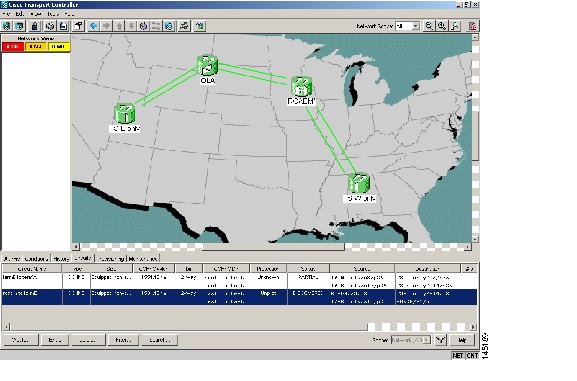
Different symptoms and scenarios can occur, depending on the network ALS settings. Consider the linear network (four nodes) in Figure 1-21 as a reference. The scenarios are presented after the figure.
Figure 1-21 Linear Network, With No Fiber Cut
1.12.1.1 Scenario A
Scenario A has the following conditions:
•
•
The ALS protocol (refer to the "Network Optical Safety—Automatic Laser Shutdown" section in the "Network Reference" chapter of the Cisco ONS 15454 DWDM Reference Manual) is activated in the event of a fiber cut, resulting in the shutdown of optical power on both of the fibers belonging to the affected span, even if only one of the two fibers is cut.
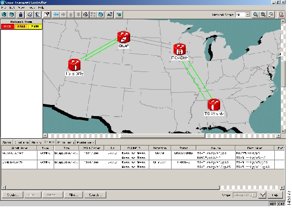
The final fault condition of the network is shown in Figure 1-22.
Figure 1-22 Fiber Cut with ALS MODE = Auto Restart
In network view, both of the lines representing the span were formerly green and have now changed to gray. Notice also that the status of all the OCHNC circuits on the broken span have changed from Discovered to Partial.
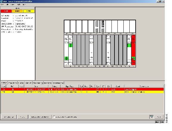
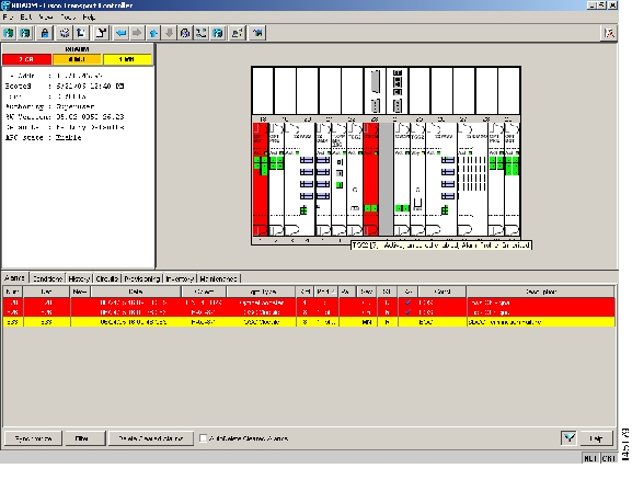
In node view (single-shelf mode) or shelf view (multishelf mode), the alarm panel of the two nodes (reconfigurable optical add/drop multiplexing [ROADM] and optical line amplification [OLA] in the example) show the LOS (AOTS) alarm on Port 4 of the OSC-CSM (see Figure 1-23) and the LOS (OTS) on Port 5 of the OPT-BST (see Figure 1-24).
Figure 1-23 LOS Indication on the ROADM Node OSC-CSM
Figure 1-24 LOS Indication on the OLA Node OPT-BST
Note
Note
1.12.1.2 Scenario B
Scenario B has the following conditions:
•
•
Because the ALS protocol is disabled, the signal is lost on only the affected fiber (power is not shut down on both fibers).
The LOS (OTS or AOTS) alarm is raised by the ROADM-RX node that was receiving the signal coming from the broken fiber. The final fault condition of the network is shown in Figure 1-25.
Figure 1-25 Network View Fault Condition for Fiber Cut with ALS Mode Disabled
In network view ( Figure 1-25), only the actual affected fiber becomes gray, whereas the traffic (and OSC signal as well) on the good fiber is active and fault identification is immediate.
In node view (single-shelf mode) or shelf view (multishelf mode) ( Figure 1-26 and Figure 1-27), the alarm panel of the receiving node (ROADM in this example) reports the LOS (OTS), while the transmitting node (OLA) reports only an EOC alarm.
Figure 1-26 ONS 15454 SDH ROADM Node View with Fault Condition for ALS MODE Disabled
Figure 1-27 ONS 15454 SDH OLA Node View with Fault Condition for ALS MODE Disabled
In order to troubleshoot and eventually fix a fiber cut, follow the "Fix a Fiber Cut" procedure. The basic assumption is that the MSTP system was already installed and working correctly before the alarm condition occurred. For first installation or restart from a fiber cut, refer to System Restart after a Fiber Cut.
Fix a Fiber Cut
Caution
Step 1
a.
b.
Step 2
a.
b.
c.
Note
Step 3
Note
Step 4
a.
b.
c.
d.
•
•
e.
f.
Step 5
Warning
Note
1.12.2 System Restart after a Fiber Cut
When the network ALS setting is Auto Restart, the system automatically restarts after a fiber cut occurs. MSTP system restart after a fiber cut is a fully automatic process regulated by a chronological sequence of steps including the OSC link built-in amplifiers restart and amplifier power control (APC) regulation.
The successful completion of system restart is strictly related to possible changes of the insertion loss value of the repaired span. A change in insertion loss is dependent on many factors, including the process of physically repairing the fiber, a change in fiber length after repair, and so on.
Four different scenarios related to span loss are presented in this section:
1.
•
•
2.
•
•
3.
4.
Note
These conditions are identified by specific alarms (see the "HI-RX-POWER" section of Chapter 2, "Alarm Troubleshooting" of the DWDM Alarm and Troubleshooting Guide).
The symptoms of the possible span loss scenarios (except for span loss decrease) are described in the following paragraphs. Refer to the linear network in Figure 1-21 during the discussion of the scenarios.
The basic assumption is that the network ALS feature (for feature details, refer to the "Network Optical Safety--Automatic Laser Shutdown" section in the Cisco ONS 15454 DWDM Reference Manual) is active (ALS Mode = Auto Restart on the OPT-BST [+ OSCM] and OSC-CSM). Given this assumption, the starting condition is as shown in Figure 1-22.
The system behavior when the network ALS Mode is DISABLE is a subcase that requires a manual restart after repairing a single fiber in only one line direction.
Note
1.12.2.1 Scenario 1: Span Loss Change > 5 dBm and OSC Power Value on the Receiver < -42 dBm
In network view, both of the lines representing the span remain gray as long as the status of the OCHNC circuits relating to the repaired span remain in Partial state.
In node view (single-shelf mode) or shelf view (multishelf mode), the alarm panels of the two nodes (ROADM and OLA in this example) show the LOS (OTS or AOTS) condition on the LINE-RX port of the OPT-BST or OSC-CSM.
An EOC condition is always present on both nodes because the OSC optical link is down due to an incoming power level lower than the optical sensitivity limit (-42 dBm). The system condition remains unchanged as illustrated in Figure 1-22.
Every 100 seconds, the ALS protocol turns up the OSC TX laser in a pulse mode (pulse duration = 2 seconds), but the excessive loss on the span prevents the OSC link from synchronizing, and the MSTP system remains unoperational.
Note
Corrective Action for Scenario 1
Step 1
a.
b.
c.
d.
e.
Note
Step 2
a.
b.
c.
d.
•
•
•
e.
•
•
Note
Step 3
Step 4
Step 5
Step 6
Step 7
Warning
Note
Note
1.12.2.2 Scenario 2: Span Loss Change > 5 dBm and OSC Power Value on the Receiver > -42 dBm
In network view, both of the lines representing the span change to green; however, the status of the OCHNC circuits relating to the repaired span remains Partial, instead of Complete (due to the fiber cut).
This change is due to the fact the physical optical power value received by the OSC transceiver is above the sensitivity limit (-42 dBm) and consequently, the OSC optical link can be rebuilt, allowing the restoration of the Section DCC (SDCC) or multiplex section DCC (MS-DCC). The network view for this condition is shown in Figure 1-28.
Figure 1-28 Network View for Span Loss Change > 5 dBm and OSC Power Value at Receiver > -42 dBm
In node view (single-shelf mode) or shelf view (multishelf mode), the EOC condition is cleared, but the alarm panels of the two nodes (ROADM and OLA in the example) continue to show LOS (OTS or AOTS) on the LINE-RX port of the OPT-BST or OSC-CSM.
The network ALS protocol keeps the OCHNC traffic down along the span because the new losses of the restored span can potentially affect the optical validation of the network design done by Cisco MetroPlanner.
Corrective Action for Scenario 2
Step 1
Step 2
a.
b.
c.
d.
e.
Note
Step 3
a.
b.
Note
Step 4
Step 5
Step 6
Step 7
Warning
Note
Step 8
a.
b.
c.
d.
If an OPT-BST is present:
•
•
If an OSC-CSM is present:
•
•
Step 9
Step 10
Step 11
a.
b.
c.
d.
e.
If the LOS alarm is still present, continue with Step 12.
Step 12
If an OPT-BST is present:
•
•
If an OSC-CSM is present:
•
•
Note
Step 13
1.12.2.3 Scenario 3: 3 dBm < Span Loss Change < 5 dBm
In network view, both of the lines representing the span change to green after the rebuild of the OSC optical link and consequent restoration of the SDCC or MS-DCC. The EOC condition and the LOS alarms are cleared.
The network ALS protocol successfully restarts the amplifiers, which enables the OCHNC traffic restoration along the span.
The reactivation of the OCHNC circuits relating to the repaired span (the status changes from Partial to Complete) can lead to several final conditions that depend on the network topology and node layout.
The rebuilding of circuits automatically triggers the APC check mechanism (for details, refer to the "Network Reference" chapter of the Cisco ONS 15454 DWDM Reference Manual). The APC check mechanism impacts the optical gain of the amplifiers (primarily the OPT-PRE card) and the VOA express attenuation for the optical add/drop multiplexing (OADM) cards. The APC application acts on the appropriate cards downstream of the repaired span (for each line direction), and attempts to compensate for the introduction of excess loss.
Because the loss increase exceeds the maximum variation (+/-3 dBm) for which APC is allowed to compensate, an APC-CORRECTIO N-SKIPPED condition is raised by the first node along the flow detecting the event. The condition panel of the impacted node (the ROADM, in this example) reports the APC-CORRECTION-SKIPPED condition and indicates the port or card to which it applies.
To correct Scenario 3:
Step 1
Step 2
a.
b.
c.
d.
Note
Step 3
a.
b.
Note
Step 4
Step 5
Step 6
Step 7
Warning
Note
Step 8
a.
b.
•
•
c.
d.
e.
f.
g.
•
•
h.
i.
j.
k.
Note
l.
•
•
•
•
•
Note
Step 9
Step 10
1.12.2.4 Scenario 4: Span Loss Change < 3 dB
In network view, both the lines that represent the span turn green after the rebuilding of the OSC optical link and consequent restoration of the SDCC or MS-DCC. The EOC condition and LOS alarms are cleared.
The network ALS protocol successfully completes the amplifier restart to enable OCHNC traffic restoration along the span.
The rebuilding of circuits automatically triggers the APC check mechanism (for details, refer to the "Network Reference" chapter of the Cisco ONS 15454 DWDM Reference Manual). The APC check mechanism affects the optical gain of the amplifiers (primarily the OPT-PRE) and the VOA express attenuation for the OADM cards. The APC application acts on the "suitable" cards downstream of the repaired span (for each line direction), and attempts to compensate for the introduction of excess loss.
The APC operation is successfully completed if enough margin during the Cisco MetroPlanner network design phase has been taken into account. If not, the adjustment done by the APC application overcomes the range setting for a specific optical parameter in the first appropriate card along the flow and an APC-OUT-OF-RANGE condition is raised. The condition panel of the impacted node (the ROADM in the example) reports the APC-OUT-OF-RANGE condition and indicates the port or card to which it applies.
To correct Scenario 4:
Step 1
Step 2
a.
b.
c.
d.
Note
Step 3
a.
b.
Note
Step 4
Step 5
•
•
Step 6
Step 7
Step 8
Warning
Note
Note
Step 9
Step 10
1.12.3 OCHNC Circuits Creation Failure
OCHNC circuit creation is managed by the Cisco Wavelength Path Provisioning (WPP) network application. The WPP application helps prevent errors during new circuit activation (if the wavelength is already allocated in the path between source and destination) and also guarantees an appropriate time interval between one circuit activation and the next to enable proper amplifier gain regulation by APC.
WPP uses the network topology information carried by the OSC link among different nodes to identify the routing path of the optical wavelength (OCHNC circuits) from the source node to the destination node. WPP also enables the card ports of the OCHNC circuits by changing the administrative state from the default (OOS or Locked) state to the final (IS or Unlocked) state.
1.12.3.1 Prerequisites for Successful OCHNC Circuit Creation
The prerequisite conditions for successfully completed circuit creation are:
1.
2.
3.
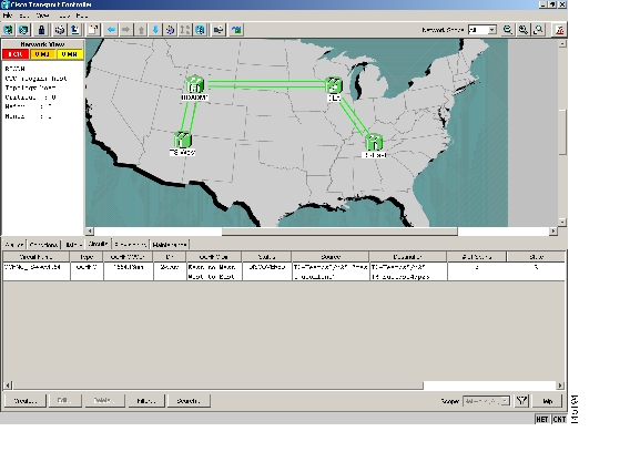
OCHNC circuit creation is successfully completed when the CTC circuit table reports the situation shown in Figure 1-29.
•
•
•
Figure 1-29 OCHNC Circuit Successfully Completed
1.12.3.2 Conditions for OCHNC Circuit Creation Failure
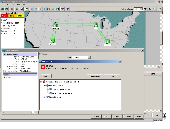
If the OCHNC circuit creation fails, you will see one of the following conditions:
•
Figure 1-30 Partial Circuit
•
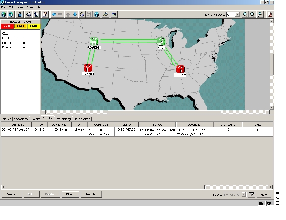
Figure 1-31 Circuit Discovered, State OSS
•
The root cause identification for the preceding conditions are found in the prerequisite conditions described in Prerequisites for Successful OCHNC Circuit Creation.
1.12.3.3 Scenarios for OCHNC Circuit Creation Failure
The most common scenarios for failure to create an OCHNC circuit are:
1.
a.
b.
c.
To troubleshoot and eventually fix issues related to the faulty OCHNC circuit creation shown in Figure 1-30, the following procedure must be performed.
Step 1
a.
b.
Note
Complete one of the following actions depending on OSC connectivity:
•
Note
•
Step 2
a.
b.
•
Note
•
Step 3
a.
b.
Step 4
Tip
If some connections are missing, perform the proper procedure according to "Turn Up a Node" in the Cisco ONS 15454 DWDM Procedure Guide.
Step 5
1.13 Node Level (Intranode) Problems
Troubleshooting for node-level optical channel (OCH) VOA start-up failure is discussed in this section.
A dedicated VOA regulates the optical power for every single channel (single wavelength) inserted in the MSTP system through a WSS, 32MUX-O, or AD-xC-xx.x card.
The final state for the VOAs is the power control working mode. In this mode, the attenuation that the VOA introduces is automatically set based on the feedback provided from a dedicated photodiode, so that a specific power setpoint value is reached and maintained.
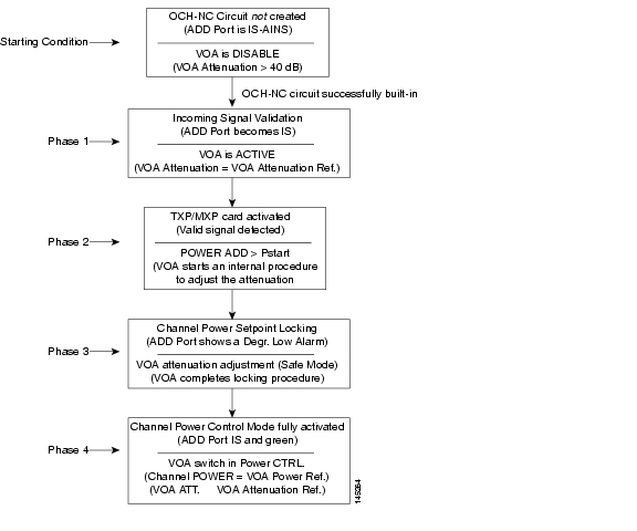
1.13.1 VOA Startup Phases
The final VOA condition is achieved through a startup procedure divided into the four sequential phases shown in Figure 1-32.
Figure 1-32 VOA Startup Procedure
Until the VOA has completed all the phases shown in Figure 1-32, the power control mode is not fully activated.
1.13.1.1 Phase 1: Incoming Signal Validation
The Incoming Signal Validation phase checks to see that the optical interface connection is valid and that the optical power level is appropriate.
Cisco MetroPlanner calculates the VOA Attenuation Reference value to allow only supported MSTP interfaces to overcome the power start-up (Pstart-up) acceptance level. (Refer to the "Network Reference" chapter of the Cisco ONS 15454 DWDM Reference Manual.)
If the interface that is connected has a power value outside the allowed range, the Phase 1 check prevents OCHNC turn-up.
1.13.1.2 Phase 2: Valid Signal Detected
If Phase 1 indicates that the signal is valid, an automatic iterative attenuation adjustment on the VOA takes place to reach a power target on the photodiode downstream of the VOA.
Note
1.13.1.3 Phase 3: Channel Power Setpoint Locking
In Phase 3, the VOA is kept in a transient standby condition when a steady power value close enough to the final power setpoint has been reached (nominally 3 dBm lower).
The duration of the transient standby condition is three seconds (by default) and allows safe management of optical interfaces that have different signal rise time values or are undergoing a pulse startup procedure compliant with the ITU-T G664 recommendation.
1.13.1.4 Phase 4: Channel Power Control Mode Fully Activated
The VOA reaches the final attenuation condition that leads the power value that is read on the photodiode to the expected target value (VOA Power Reference). Simultaneously, the VOA operating mode switches to power control mode.
From this point on, any further adjustment of the VOA attenuation is triggered by a variation of the value read on the photodiode. The aim of these adjustments is to always keep the power value equal to the power setpoint, with +/- 0.5 dBm as the minimum adjustment increment.
1.13.2 VOA Failure Scenarios
Several conditions can stop the startup procedure at an intermediate step, blocking the VOA (and the circuit activation, as a consequence) from completing activation of the power control mode. The scenarios in this section portray those conditions.
Root-cause identification can be performed based on the alarm raised and the power reading on the photodiode associated with the VOA.
1.13.2.1 Scenario A: Optical Power Level of the Incoming Signal Lower Than Minimum Allowed by MSTP Supported Optical Interfaces
This scenario is for a condition where a TXP or MXP card is directly connected to a 32MUX-O or 32WSS card where power in is expressed as Pin < -4.5 dBm.
If the incoming power level is lower than the minimum allowed, the startup procedure always stops at Phase 1 (see Figure 1-33). This is the case even if the final VOA Power Reference reported in CTC is reachable.
The final conditions that CTC reports are:
•
•
Figure 1-33 LOS-P Indication on the VOA Port
Use the following procedure to troubleshoot and eventually fix issues related to the VOA start-up when the optical power level of the incoming signal is lower than the minimum allowed by the MSTP supported optical interfaces (32MUX-O and 32WSS cards).
Step 1
a.
b.
c.
d.
e.
f.
Note
Step 2
a.
b.
Note
c.
d.
Note
e.
f.
•
•
•
g.
h.
i.
j.
k.
Warning
Step 3
•
•
•
If the TX laser is active, the wavelength is provisioned properly, and the output power value is in the correct range, go to Step 4. Otherwise, take the appropriate corrective action, including card replacement if the output power value is outside of the expected range (refer to the "Add and Remove Cards and Nodes" chapter of the Cisco ONS 15454 DWDM Procedure Guide. Replacing the card should correct the problem.)
Warning
Step 4
a.
Note
b.
c.
d.
Note
Note
Step 5
•
•
•
If the TX laser is active, the wavelength is provisioned properly, and the output power value is in the correct range, go to Step 6. Otherwise, take the appropriate corrective action, including card replacement if the output power value is outside of the expected range (refer to the "Add and Remove Cards and Nodes" chapter of the Cisco ONS 15454 DWDM Procedure Guide. Replacing the card should correct the problem.)
Warning
Step 6
a.
Note
b.
c.
d.
e.
Note
f.
Step 7
a.
b.
•
•
c.
d.
•
•
•
e.
f.
g.
Warning
1.13.2.2 Scenario B: Optical Power Level of the Incoming Signal Lower Than Expected
In some cases, the pass-through channels on the 32WSS card or the optical bypass channels on the 32MUX-O card are at a power level that is lower than expected. The incoming power level can be lower than expected for several reasons. A few examples are:
•
•
•
When the power is lower than expected, the start-up procedure can stop at Phase 1, Phase 2, or Phase 3 (see Figure 1-32). The point at which the start-up procedure stops depends on the amount of power missing.
Given that Delta Power is the amount of optical power missing compared to the expected value, two final conditions for Scenario B can be identified, Conditions B1 and B2.
1.13.2.2.1 Condition B1—Delta Power > 6 dB (LOS-P Alarm)
When the optical power is more than 6 dB lower than the expected value, the final VOA Power Reference setpoint value is definitively not reachable and even Phase 1 of the start-up procedure cannot be properly completed. As a consequence, the final condition reported in CTC is the same as that of Scenario A:
•
•
Figure 1-34 Power Level of Incoming Signal Less than -33 dBm
1.13.2.2.2 Condition B2—Delta Power < 6 dB (OPWR-LowDEGrade Alarm)
When the optical power is less than 6 dB lower than the expected value, even if a valid incoming signal is present, the final VOA Power Reference setpoint value that is reported in the CTC is not reachable and the VOA startup procedure is stopped at Phase 3.
The final conditions that CTC reports are:
•
•
Figure 1-35 Optical Power Less than 6 dB Lower than Expected
Corrective Actions for Scenario B (Optical Power Level of Incoming Signal Lower than Expected)
When the optical power level of the incoming signal is lower than expected for the pass-through channels on the 32WSS or the optical bypass channels on the 32MUX-O card, use the following procedures to troubleshoot and eventually fix issues related to VOA start-up. According to the final conditions reported by the card (either LOS-P alarm for condition B1 or OPWR-LowDEGrade for condition B2), two troubleshooting procedures are suggested. These procedures are given in the following sections.
Condition B1—LOS-P Alarm
Step 1
a.
b.
c.
d.
e.
f.
Note
Step 2
Step 3
a.
•
Note
•
Step 4
a.
b.
c.
Step 5
Step 6
Step 7
a.
b.
Note
c.
d.
•
•
•
e.
f.
g.
h.
i.
Step 8
a.
b.
c.
d.
e.
Note
Note
f.
Warning
Step 9
a.
b.
c.
d.
e.
Note
f.
•
•
•
g.
h.
i.
Step 10
a.
Note
b.
•
Note
•
c.
d.
e.
f.
Note
g.
Warning
Condition B2—OPWR-LowDEGrade Alarm
Step 1
a.
b.
c.
d.
e.
f.
Note
Step 2
Step 3
a.
Note
b.
Step 4
a.
b.
c.
Step 5
Step 6
Step 7
a.
b.
c.
d.
e.
Note
Note
Note
Step 8
a.
Note
b.
•
Note
•
c.
d.
e.
f.
Note
Note
1.13.2.3 Scenario C: Optical Drop Power Level Lower Than Expected
This scenario describes the condition in which the optical power at the 32DMX-O drop channels is lower than expected. The 32DMX-O card is equipped with a VOA for each wavelength, and each VOA manages the power for one dropped wavelength.
The failing scenarios during the OCHNC turn-up and consequent VOA startup are the same as those described in the "Scenario B: Optical Power Level of the Incoming Signal Lower Than Expected" section. The only difference is the type of alarm that is raised when the condition exists in which Delta Power is greater than 6 dB.
1.13.2.3.1 Condition C1—Delta Power > 6 dB Lower than Expected
When the optical power on the dropped channel is more than 6 dB lower that the value expected, the final VOA Power Reference setpoint value is definitively not reachable. As a consequence, the final conditions reported in CTC are as follows:
•
•
Figure 1-36 Optical Drop Power More than 6 dB Lower than Expected
1.13.2.3.2 Condition C2—Delta Power < 6 dB Lower than Expected
If the delta power is less than 6 dB lower than expected, the final conditions reported in CTC are the same as those reported for Condition B2 (see the "Condition B2—Delta Power < 6 dB (OPWR-LowDEGrade Alarm)" section):
•
•
A dirty connection or excessive loss of the incoming span are among the possible reasons that can lead to a fault condition. They are the most common and affect all wavelengths, whereas an excessive amplifier gain tilt or a wavelength misconfiguration on the far-end TXP or MXP card can lead to condition where only a single wavelength fails, such as the one (Channel 25) shown in Figure 1-37.
Figure 1-37 Optical Drop Power Less than 6 dB Lower than Expected
Corrective Action for Scenario C (Optical Power Level of Incoming Signal Lower than Expected)
Scenario C1 - LOS-P Alarm
Step 1
a.
b.
c.
d.
e.
f.
Note
Step 2
a.
b.
•
Note
•
c.
•
•
d.
e.
Step 3
a.
b.
c.
d.
e.
Note
f.
•
•
•
g.
h.
i.
Step 4
a.
b.
c.
d.
e.
Warning
Note
Note
f.
Warning
Scenario C2 - OPWR-LowDEGrade Alarm
Step 1
a.
b.
c.
d.
e.
f.
Note
Step 2
a.
b.
•
Note
•
c.
•
•
d.
e.
Step 3
a.
b.
c.
d.
e.
Warning
Note
Note
f.
![]()
![]()
![]()
![]()
![]()
![]()
![]()
![]()
Posted: Tue Mar 6 16:41:16 PST 2007
All contents are Copyright © 1992--2007 Cisco Systems, Inc. All rights reserved.
Important Notices and Privacy Statement.