|
|

Table Of Contents
2.1.2 Front Mount Electrical Connections (ETSI only)
2.1.4 Transponder and Muxponder Cards
2.1.7 Multiplexer, Demultiplexer, and OADM Card Interface Classes
2.1.8 DWDM Card Channel Allocation Plan
2.2.1 Class 1 Laser Product Cards
2.2.2 Class 1M Laser Product Cards
2.4 Front Mount Electrical Connections
2.5 Optical Service Channel Cards
2.6.3 OPT-BST-E Amplifier Card
2.6.4 OPT-BST-L Amplifier Card
2.7 Multiplexer and Demultiplexer Cards
2.8 Optical Add/Drop Multiplexer Cards
2.9 Transponder and Muxponder Cards
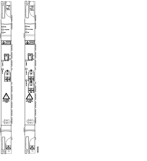
2.9.3 TXP_MR_10E_C and TXP_MR_10E_L Cards
2.9.4 TXP_MR_2.5G and TXPP_MR_2.5G Cards
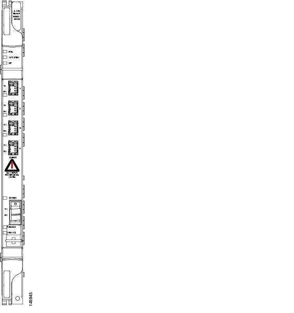
2.9.7 MXP_2.5G_10E_C and MXP_2.5G_10E_L Cards
2.9.8 MXP_MR_2.5G and MXPP_MR_2.5G Cards
2.9.9 MXP_MR_10DME_C and MXP_MR_10DME_L Cards
2.10 Transponder and Muxponder Protection
2.14.2 SFP and XFP Description
Card Reference
Note
The terms "Unidirectional Path Switched Ring" and "UPSR" may appear in Cisco literature. These terms do not refer to using Cisco ONS 15xxx products in a unidirectional path switched ring configuration. Rather, these terms, as well as "Path Protected Mesh Network" and "PPMN," refer generally to Cisco's path protection feature, which may be used in any topological network configuration. Cisco does not recommend using its path protection feature in any particular topological network configuration.
This chapter describes Cisco ONS 15454 dense wavelength division multiplexing (DWDM) card and client card features and functions. It also describes the common control cards needed to support them as well as the optical plug-in modules (Small Form-factor Pluggables [SFPs]). For installation and card turn-up procedures, refer to the Cisco ONS 15454 DWDM Procedure Guide. For card safety and compliance information, refer to the Cisco Optical Transport Products Safety and Compliance Information document.
Note
Chapter topics include:
•
•
•
•
•
•
2.1 Card Overview
The card overview section lists the cards described in this chapter and summarizes card functions, power consumption, and temperature ranges of the optical cards covered in this reference section.
Note
2.1.1 Common Control Cards
The following common control cards are needed to support the functions of the DWDM, transponder, and muxponder cards:
•
•
•
2.1.2 Front Mount Electrical Connections (ETSI only)
The following Front Mount Electrical Connections (FMECs) are needed to support the functions of the DWDM, transponder, and muxponder cards:
•
•
2.1.3 DWDM Cards
ONS 15454 DWDM cards are grouped into the following categories:
•
•
•
•
•
2.1.4 Transponder and Muxponder Cards
The purpose of a transponder (TXP) or muxponder (MXP) card is to convert the "gray" optical client interface signals into trunk signals that operate in the "colored" DWDM wavelength range1 . Transponding or muxponding is the process of converting the signals between the client and trunk wavelengths.
A muxponder generally handles several client signals. It aggregates, or multiplexes, lower rate client signals together and sends them out over a higher rate trunk port. Likewise, it demultiplexes optical signals coming in on a trunk and sends them out to individual client ports. A transponder converts a single client signal to a single trunk signal and converts a single incoming trunk signal to a single client signal.
All of the TXP and MXP cards perform optical to electrical to optical (OEO) conversion. As a result, they are not optically transparent cards. The reason for this is that the cards must operate on the signals passing through them, so it is necessary to do an OEO conversion.
On the other hand, the termination mode for all of the TXPs and MXPs, which is done at the electrical level, can be configured to be transparent. In this case, neither the Line nor the Section overhead is terminated. The cards can also be configured so that either Line or Section overhead can be terminated, or both can be terminated.
Note
2.1.5 Card Summary
Table 2-1 lists and summarizes the functions of each Cisco ONS 15454 DWDM and client card.
Table 2-1 DWDM and Client Cards for the ONS 15454
The OSCM has one set of optical ports and one Ethernet port located on the faceplate. It operates in Slots 8 and 10.
See the "OSCM Card" section.
The OSC-CSM has three sets of optical ports and one Ethernet port located on the faceplate. It operates in Slots 1 to 6 and 12 to 17.
See the "OSC-CSM Card" section.
The OPT-PRE amplifier has five optical ports (three sets) located on the faceplate. It operates in Slots 1 to 6 and 12 to 17.
See the "OPT-PRE Amplifier" section.
The OPT-BST amplifier has four sets of optical ports located on the faceplate. It operates in Slots 1 to 6 and 12 to 17.
See the "OPT-BST Amplifier Card" section.
The OPT-BST-E amplifier has four sets of optical ports located on the faceplate. It operates in Slots 1 to 6 and 12 to 17.
See the "OPT-BST-E Amplifier Card" section.
The OPT-BST-L L-band amplifier has four sets of optical ports located on the faceplate. It operates in Slots 1 to 6 and 12 to 17.
See the "OPT-BST-L Amplifier Card" section.
The OPT-AMP-L L-band preamplifier have five sets of optical ports located on the faceplate. It is a two-slot card that operates in Slots 1 to 6 and 12 to 17.
See the "OPT-AMP-L Card" section.
The 32MUX-O has five sets of ports located on the faceplate. It operates in Slots 1 to 5 and 12 to 16.
See the "32MUX-O Card" section.
The 32DMX-O has five sets of ports located on the faceplate. It operates in Slots 1 to 5 and 12 to 16.
See the "32DMX-O Card" section.
The 32DMX has five sets of ports located on the faceplate. It operates in Slots 1 to 6 and 12 to 17.
See the "32DMX Card" section
The 32DMX-L has five sets of ports located on the faceplate. It operates in Slots 1 to 6 and 12 to 17.
See the "32DMX-L Card" section
The 4MD-xx.x card has five sets of ports located on the faceplate. It operates in Slots 1 to 6 and 12 to 17.
See the "4MD-xx.x Card" section.
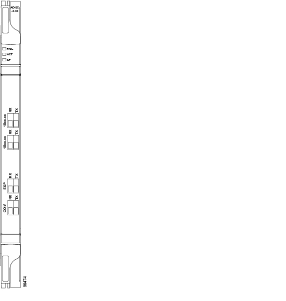
The AD-1C-xx.x card has three sets of ports located on the faceplate. It operates in Slots 1 to 6 and 12 to 17.
See the "AD-1C-xx.x Card" section.
The AD-2C-xx.x card has four sets of ports located on the faceplate. It operates in Slots 1 to 6 and 12 to 17.
See the "AD-2C-xx.x Card" section.
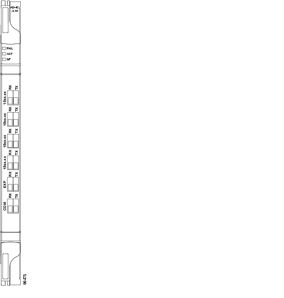
The AD-4C-xx.x card has six sets of ports located on the faceplate. It operates in Slots 1 to 6 and 12 to 17.
See the "AD-4C-xx.x Card" section.
The AD-1B-xx.x card has three sets of ports located on the faceplate. It operates in Slots 1 to 6 and 12 to 17.
See the "AD-1B-xx.x Card" section.
The AD-4B-xx.x card has six sets of ports located on the faceplate. It operates in Slots 1 to 6 and 12 to 17.
See the "AD-4B-xx.x Card" section.
The 32WSS card has seven sets of ports located on the faceplate. It operates in Slots 1 to 5 and 12 to 16.
See the "32WSS Card" section
The 32WSS-L card has seven sets of ports located on the faceplate. It operates in Slots 1 to 5 and 12 to 16.
See the "32WSS-L Card" section
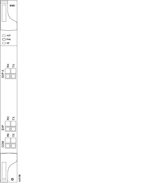
The MMU card has six sets of ports located on the faceplate, It operates in slots 1 to 6 and 12 to 17.
See the "MMU Card" section
The TXP_MR_10G card has two sets of ports located on the faceplate.
See the "TXP_MR_10G Card" section
The TXP_MR_10E card has two sets of ports located on the faceplate.
See the "TXP_MR_10E Card" section
The TXP_MR_10E_C and TXP_MR_10E_L cards have two sets of ports located on the faceplate.
The TXP_MR_2.5G card has two sets of ports located on the faceplate.
The TXPP_MR_2.5G card has three sets of ports located on the faceplate.
The MXP_2.5G_10G card has nine sets of ports located on the faceplate.
See the "MXP_2.5G_10G Card" section.
The MXP_2.5G_10E card has nine sets of ports located on the faceplate.
See the "MXP_2.5G_10E Card" section
MXP_2.5G_10E_LThe MXP_2.5G_10E_C and MXP_2.5G_10E_C cards have nine sets of ports located on the faceplate.
The MXP_MR_2.5G card has nine sets of ports located on the faceplate.
The MXPP_MR_2.5G card has ten sets of ports located on the faceplate.
The MXP_MR_10DME_C and MXP_MR_10DME_L cards have eight sets of ports located on the faceplate.
2.1.6 Card Compatibility
Table 2-2 lists the CTC software compatibility for each DWDM and client card.
2.1.7 Multiplexer, Demultiplexer, and OADM Card Interface Classes
The 32MUX-O, 32WSS, 32WSS-L, 32DMX, 32DMX-L, 32DMX-O, 4MD-xx.x, and AD-1C-xx.x cards have different input and output optical channel signals depending upon the interface card where the input signal originates. The input interface cards have been grouped in classes listed in Table 2-3. The subsequent tables list the optical performances and output power of each interface class.
10-Gbps cards that provide signal input to OADM cards have the optical performance parameters listed in Table 2-4. 2.5-Gbps card interface performance parameters are listed in Table 2-5.
Table 2-4 10-Gbps Interface Optical Performance
Maximum bit rate
10 Gbps
10 Gbps
10 Gbps
10 Gbps
Regeneration
3R
3R
3R
3R
FEC
Yes
No
No
Yes (E-FEC)
Threshold
Optimum
Average
Average
Optimum
Maximum BER2
10-15
10-12
10-12
10-15
OSNR 1 sensitivity
23 dB
9 dB
23 dB
19 dB
19 dB
20 dB
8 dB
Power sensitivity
-24 dBm
-18 dBm
-21 dBm
-20 dBm
-22 dBm
-26 dBm
-18 dBm
Power overload
-8 dBm
-8 dBm
-9 dBm
-8 dBm
Transmitted Power Range3
10-Gbps multirate transponder/10-Gbps FEC transponder (TXP_MR_10G)
+2.5 to 3.5 dBm
+2.5 to 3.5 dBm
—
—
OC-192 LR ITU
—
—
+3.0 to 6.0 dBm
—
10-Gbps multirate transponder/10-Gbps FEC transponder (TXP_MR_10E)
+3.0 to 6.0 dBm
+3.0 to 6.0 dBm
—
+3.0 to 6.0 dBm
Dispersion compensation tolerance
+/-800 ps/nm
+/-1,000 ps/nm
+/-1,000 ps/nm
+/-800 ps/nm
1 OSNR = optical signal-to-noise ratio
2 BER = bit error rate
3 These values, decreased by patchcord and connector losses, are also the input power values for the OADM cards.
Table 2-5 2.5-Gbps Interface Optical Performance
Maximum bit rate
2.5 Gbps
2.5 Gbps
2.5 Gbps
2.5 Gbps
1.25 Gbps
2.5 Gbps
Regeneration
3R
3R
2R
3R
3R
3R
FEC
Yes
No
No
No
No
No
Threshold
Average
Average
Average
Average
Average
Average
Maximum BER
10-15
10-12
10-12
10-12
10-12
10-12
OSNR sensitivity
14 dB
6 dB
14 dB
10 dB
15 dB
14 dB
11 dB
13 dB
8 dB
12 dB
Power sensitivity
-31 dBm
-25 dBm
-30 dBm
-23 dBm
-24 dBm
-27 dBm
-33 dBm
-28 dBm
-18 dBm
-26 dBm
Power overload
-9 dBm
-9 dBm
-9 dBm
-9 dBm
-7 dBm
-17dBm
Transmitted Power Range1
TXP_MR_2.5G
-1.0 to 1.0 dBm
-1.0 to 1.0 dBm
-1.0 to 1.0 dBm
-2.0 to 0 dBm
TXPP_MR_2.5G
-4.5 to -2.5 dBm
-4.5 to -2.5 dBm
-4.5 to -2.5 dBm
MXP_MR_2.5G
—
+2.0 to +4.0 dBm
—
MXPP_MR_2.5G
—
-1.5 to +0.5 dBm
—
2/4 port GbE Transponder (GBIC WDM 100GHz)
+2.5 to 3.5 dBm
—
Dispersion compensation tolerance
-1200 to +5400 ps/nm
-1200 to +5400 ps/nm
-1200 to +3300 ps/nm
-1200 to +3300 ps/nm
-1000 to +3600 ps/nm
-1000 to +3200 ps/nm
1 These values, decreased by patchcord and connector losses, are also the input power values for the OADM cards.
2.1.8 DWDM Card Channel Allocation Plan
ONS 15454 DWDM multiplexers, demultiplexers, channel OADM, and band OADM cards are designed for use with specific channels in the C band and L band. In most cases, the channels for these cards are either numbered (for example, 1 to 32) or delimited (odd or even). Client interfaces must comply with these channel assignments to be compatible with the ONS 15454 system.
Table 2-6 lists the channel IDs and wavelengths assigned to the C-band DWDM channels and Table 2-7 lists the channel IDs and wavelengths assigned to the L-band channels.
Note
2.2 Safety Labels
This section explains the significance of the safety labels attached to some of the cards. The faceplates of the cards are clearly labeled with warnings about the laser radiation levels. You must understand all warning labels before working on these cards.
2.2.1 Class 1 Laser Product Cards
The cards that contains Class 1 Laser Products are:
•
•
•
The labels that appear on these cards are described in the following subsections.
2.2.1.1 Class 1 Laser Product Label
The Class 1 Laser Product label is shown in Figure 2-1.
Figure 2-1 Class 1 Laser Product Label
Class 1 lasers are products whose irradiance does not exceed the Maximum Permissible Exposure (MPE) value. Therefore, for Class 1 laser products the output power is below the level at which it is believed eye damage will occur. Exposure to the beam of a Class 1 laser will not result in eye injury and may therefore be considered safe. However, some Class 1 laser products may contain laser systems of a higher Class but there are adequate engineering control measures to ensure that access to the beam is not reasonably likely. Anyone who dismantles a Class 1 laser product that contains a higher Class laser system is potentially at risk of exposure to a hazardous laser beam
2.2.1.2 Hazard Level 1 Label
The Hazard Level 1 label is shown in Figure 2-2.
Figure 2-2 Hazard Level Label
The Hazard Level label warns users against exposure to laser radiation of Class 1 limits calculated in accordance with IEC60825-1 Ed.1.2.
2.2.1.3 Laser Source Connector Label
The Laser Source Connector label is shown in Figure 2-3.
Figure 2-3 Laser Source Connector Label
This label indicates that a laser source is present at the optical connector where the label has been placed.
2.2.1.4 FDA Statement Label
The FDA Statement label is shown in Figure 2-4.
Figure 2-4 FDA Statement Label
This label shows compliance to FDA standards and that the hazard level classification is in accordance with IEC60825-1 Am.2 or Ed.1.2.
2.2.1.5 Shock Hazard Label
The Shock Hazard label is shown in Figure 2-5.
Figure 2-5 Shock Hazard Label
This label alerts personnel to electrical hazard within the card. The potential of shock hazard exists when removing adjacent cards during maintenance, and touching exposed electrical circuitry on the card itself.
2.2.2 Class 1M Laser Product Cards
The cards that contains Class 1M Laser Products are:
•
•
•
•
The labels that appear on these cards are described in the following subsections.
2.2.2.1 Class 1M Laser Product Label
The Class 1M Laser Product label is shown in Figure 2-6.
Figure 2-6 Class 1M Laser Product Label
Class 1M lasers are products that produce either a highly divergent beam or a large diameter beam. Therefore, only a small part of the whole laser beam can enter the eye. However, these laser products can be harmful to the eye if the beam is viewed using magnifying optical instruments.
2.2.2.2 Hazard Level 1M Label
The Hazard Level 1M label is shown in Figure 2-7.
Figure 2-7 Hazard Level Label
The Hazard Level label warns users against exposure to laser radiation of Class 1 limits calculated in accordance with IEC60825-1 Ed.1.2.
2.2.2.3 Laser Source Connector Label
The Laser Source Connector label is shown in Figure 2-8.
Figure 2-8 Laser Source Connector Label
This label indicates that a laser source is present at the optical connector where the label has been placed.
2.2.2.4 FDA Statement Label
The FDA Statement label is shown in Figure 2-9.
Figure 2-9 FDA Statement Label
This label shows compliance to FDA standards and that the hazard level classification is in accordance with IEC60825-1 Am.2 or Ed.1.2.
2.2.2.5 Shock Hazard Label
The Shock Hazard label is shown in Figure 2-5.
Figure 2-10 Shock Hazard Label
This label alerts personnel to electrical hazard within the card. The potential of shock hazard exists when removing adjacent cards during maintenance, and touching exposed electrical circuitry on the card itself.
2.3 Common Control Cards
This section describes the common control cards (TCC2, TCC2P, AIC-I, and MS-ISC-100T).
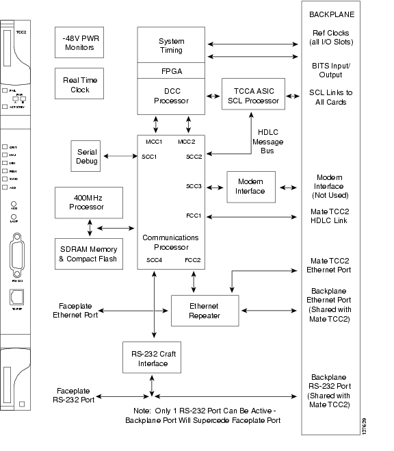
2.3.1 TCC2 Card
The Advanced Timing, Communications, and Control (TCC2) card performs system initialization, provisioning, alarm reporting, maintenance, diagnostics, IP address detection/resolution, SONET section overhead (SOH) data communications channel/generic communications channel (DCC/GCC) termination, optical service channel (OSC) DWDM data communications network (DCN) termination, and system fault detection for the ONS 15454. The TCC2 also ensures that the system maintains Stratum 3 (Telcordia GR-253-CORE) timing requirements. It monitors the supply voltage of the system.
Note
Figure 2-11 shows the faceplate and block diagram for the TCC2.
Figure 2-11 TCC2 Faceplate and Block Diagram
2.3.1.1 TCC2 Functionality
The TCC2 card terminates up to 32 DCCs. The TCC2 hardware is prepared for up to 84 DCCs, which will be available in a future software release.
The node database, IP address, and system software are stored in TCC2 nonvolatile memory, which allows quick recovery in the event of a power or card failure.
The TCC2 performs all system-timing functions for each ONS 15454. The TCC2 monitors the recovered clocks from each traffic card and two building integrated timing supply (BITS) ports for frequency accuracy. The TCC2 selects a recovered clock, a BITS, or an internal Stratum 3 reference as the system-timing reference. You can provision any of the clock inputs as primary or secondary timing sources. A slow-reference tracking loop allows the TCC2 to synchronize with the recovered clock, which provides holdover if the reference is lost.
The TCC2 monitors both supply voltage inputs on the shelf. An alarm is generated if one of the supply voltage inputs has a voltage out of the specified range.
Install TCC2 cards in Slots 7 and 11 for redundancy. If the active TCC2 fails, traffic switches to the protect TCC2.
The TCC2 card has two built-in interface ports for accessing the system: an RJ-45 10BaseT LAN interface and an EIA/TIA-232 ASCII interface for local craft access. It also has a 10BaseT LAN port for user interfaces via the backplane.
2.3.1.2 Redundant TCC2 Card Installation
Cisco does not support operation of the ONS 15454 with only one TCC2 card. For full functionality and to safeguard your system, always operate with two TCC2 cards.
When a second TCC2 card is inserted into a node, it synchronizes its software, its backup software, and its database with the active TCC2. If the software version of the new TCC2 does not match the version on the active TCC2, the newly inserted TCC2 copies from the active TCC2, taking about 15 to 20 minutes to complete. If the backup software version on the new TCC2 does not match the version on the active TCC2, the newly inserted TCC2 copies the backup software from the active TCC2 again, taking about 15 to 20 minutes. Copying the database from the active TCC2 takes about 3 minutes. Depending on the software version and backup version the new TCC2 started with, the entire process can take between 3 and 40 minutes.
2.3.1.3 TCC2 Card-Level Indicators
The TCC2 faceplate has eight LEDs. Table 2-8 describes the two card-level LEDs on the TCC2 faceplate.
2.3.1.4 Network-Level Indicators
Table 2-9 describes the six network-level LEDs on the TCC2 faceplate.
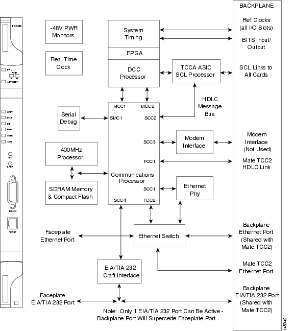
2.3.2 TCC2P Card
The Advanced Timing, Communications, and Control Plus (TCC2P) card is an enhanced version of the TCC2 card. The primary enhancements are Ethernet security features and 64K composite clock BITS timing.
The TCC2P card performs system initialization, provisioning, alarm reporting, maintenance, diagnostics, IP address detection/resolution, SONET SOH DCC/GCC termination, and system fault detection for the ONS 15454. The TCC2P also ensures that the system maintains Stratum 3 (Telcordia GR-253-CORE) timing requirements. It monitors the supply voltage of the system.
Note
Figure 2-12 shows the faceplate and block diagram for the TCC2P card.
Figure 2-12 TCC2P Faceplate and Block Diagram
2.3.3 TCC2P Functionality
The TCC2P card supports multichannel, high-level data link control (HDLC) processing for the DCC. Up to 84 DCCs can be routed over the TCC2P card and up to 84 section DCCs can be terminated at the TCC2P card (subject to the available optical digital communication channels). The TCC2P selects and processes 84 DCCs to facilitate remote system management interfaces.
The TCC2P card also originates and terminates a cell bus carried over the module. The cell bus supports links between any two cards in the node, which is essential for peer-to-peer communication. Peer-to-peer communication accelerates protection switching for redundant cards.
The node database, IP address, and system software are stored in TCC2P card nonvolatile memory, which allows quick recovery in the event of a power or card failure.
The TCC2P card performs all system-timing functions for each ONS 15454. The TCC2P card monitors the recovered clocks from each traffic card and two BITS ports for frequency accuracy. The TCC2P card selects a recovered clock, a BITS, or an internal Stratum 3 reference as the system-timing reference. You can provision any of the clock inputs as primary or secondary timing sources. A slow-reference tracking loop allows the TCC2P card to synchronize with the recovered clock, which provides holdover if the reference is lost.
The TCC2P card supports 64/8K composite clock and 6.312 MHz timing output.
The TCC2P card monitors both supply voltage inputs on the shelf. An alarm is generated if one of the supply voltage inputs has a voltage out of the specified range.
Install TCC2P cards in Slots 7 and 11 for redundancy. If the active TCC2P card fails, traffic switches to the protect TCC2P card. All TCC2P card protection switches conform to protection switching standards when the bit error rate (BER) counts are not in excess of 1 * 10 exp - 3 and completion time is less than 50 ms.
The TCC2P card has two built-in Ethernet interface ports for accessing the system: one built-in RJ-45 port on the front faceplate for on-site craft access and a second port on the backplane. The rear Ethernet interface is for permanent LAN access and all remote access via TCP/IP as well as for Operations Support System (OSS) access. The front and rear Ethernet interfaces can be provisioned with different IP addresses using CTC.
Two EIA/TIA-232 serial ports, one on the faceplate and a second on the backplane, allow for craft interface in TL1 mode.
Note
2.3.3.1 Redundant TCC2P Card Installation
Cisco does not support operation of the ONS 15454 with only one TCC2P card. For full functionality and to safeguard your system, always operate with two TCC2P cards.
When a second TCC2P card is inserted into a node, it synchronizes its software, its backup software, and its database with the active TCC2P card. If the software version of the new TCC2P card does not match the version on the active TCC2P card, the newly inserted TCC2P card copies from the active TCC2P card, taking about 15 to 20 minutes to complete. If the backup software version on the new TCC2P card does not match the version on the active TCC2P card, the newly inserted TCC2P card copies the backup software from the active TCC2P card again, taking about 15 to 20 minutes. Copying the database from the active TCC2P card takes about 3 minutes. Depending on the software version and backup version the new TCC2P card started with, the entire process can take between 3 and 40 minutes.
2.3.3.2 TCC2P Card-Level Indicators
The TCC2P faceplate has eight LEDs. Table 2-10 describes the two card-level LEDs on the TCC2P faceplate.
2.3.3.3 Network-Level Indicators
Table 2-11 describes the six network-level LEDs on the TCC2P faceplate.
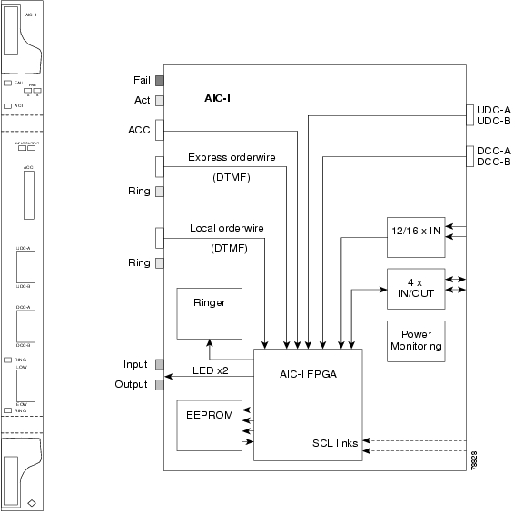
2.3.4 AIC-I Card
The optional Alarm Interface Controller-International (AIC-I) card provides customer-defined (environmental) alarms and controls and supports local and express orderwire. It provides 12 customer-defined input and 4 customer-defined input/output contacts. The physical connections are via the backplane wire-wrap pin terminals. If you use the additional alarm expansion panel (AEP), the AIC-I card can support up to 32 inputs and 16 outputs, which are connected on the AEP connectors. The AEP is compatible with ANSI shelves only. A power monitoring function monitors the supply voltage (-48 VDC). Figure 2-13 shows the AIC-I faceplate and a block diagram of the card.
Figure 2-13 AIC-I Faceplate and Block Diagram
2.3.4.1 AIC-I Card-Level Indicators
Table 2-12 describes the eight card-level LEDs on the AIC-I card faceplate.
2.3.4.2 External Alarms and Controls
The AIC-I card provides input/output alarm contact closures. You can define up to 12 external alarm inputs and 4 external alarm inputs/outputs (user configurable). The physical connections are made using the backplane wire-wrap pins or FMEC connections. See the "1.9 ONS 15454 ANSI Alarm Expansion Panel" section on page 1-31 for information about increasing the number of input/output contacts.
LEDs on the front panel of the AIC-I indicate the status of the alarm lines, one LED representing all of the inputs and one LED representing all of the outputs. External alarms (input contacts) are typically used for external sensors such as open doors, temperature sensors, flood sensors, and other environmental conditions. External controls (output contacts) are typically used to drive visual or audible devices such as bells and lights, but they can control other devices such as generators, heaters, and fans.
You can program each of the twelve input alarm contacts separately. You can program each of the sixteen input alarm contacts separately. Choices include:
•
•
•
•
You cannot assign the fan-tray abbreviation for the alarm; the abbreviation reflects the generic name of the input contacts. The alarm condition remains raised until the external input stops driving the contact or you provision the alarm input.
The output contacts can be provisioned to close on a trigger or to close manually. The trigger can be a local alarm severity threshold, a remote alarm severity, or a virtual wire:
•
•
•
You can also program the output alarm contacts (external controls) separately. In addition to provisionable triggers, you can manually force each external output contact to open or close. Manual operation takes precedence over any provisioned triggers that might be present.
Note
2.3.4.3 Orderwire
Orderwire allows a craftsperson to plug a phoneset into an ONS 15454 and communicate with craftspeople working at other ONS 15454s or other facility equipment. The orderwire is a pulse code modulation (PCM) encoded voice channel that uses E1 or E2 bytes in section/line overhead.
The AIC-I allows simultaneous use of both local (section overhead signal) and express (line overhead channel) orderwire channels on a SONET/SDH ring or particular optics facility. Express orderwire also allows communication via regeneration sites when the regenerator is not a Cisco device.
You can provision orderwire functions with CTC similar to the current provisioning model for DCC/GCC channels. In CTC, you provision the orderwire communications network during ring turn-up so that all NEs on the ring can reach one another. Orderwire terminations (that is, the optics facilities that receive and process the orderwire channels) are provisionable. Both express and local orderwire can be configured as on or off on a particular SONET/SDH facility. The ONS 15454 supports up to four orderwire channel terminations per shelf. This allows linear, single ring, dual ring, and small hub-and-spoke configurations. Orderwire is not protected in ring topologies such as bidirectional line switched ring (BLSR), multiplex section-shared protection ring (MS-SPRing), path protection, or subnetwork connection protection (SNCP) ring.
Caution
The ONS 15454 implementation of both local and express orderwire is broadcast in nature. The line acts as a party line. Anyone who picks up the orderwire channel can communicate with all other participants on the connected orderwire subnetwork. The local orderwire party line is separate from the express orderwire party line. Up to four OC-N/STM-N facilities for each local and express orderwire are provisionable as orderwire paths.
The AIC-I supports selective dual tone multifrequency (DTMF) dialing for telephony connectivity, which causes one AIC-I card or all ONS 15454 AIC-I cards on the orderwire subnetwork to "ring." The ringer/buzzer resides on the AIC-I. There is also a "ring" LED that mimics the AIC-I ringer. It flashes when a call is received on the orderwire subnetwork. A party line call is initiated by pressing *0000 on the DTMF pad. Individual dialing is initiated by pressing * and the individual four-digit number on the DTMF pad.
Table 2-13 shows the pins on the orderwire connector that correspond to the tip and ring orderwire assignments.
Table 2-13 Orderwire Pin Assignments
1
Four-wire receive ring
2
Four-wire transmit tip
3
Two-wire ring
4
Two-wire tip
5
Four-wire transmit ring
6
Four-wire receive tip
When provisioning the orderwire subnetwork, make sure that an orderwire loop does not exist. Loops cause oscillation and an unusable orderwire channel.
Figure 2-14 shows the standard RJ-11 connectors used for orderwire ports.
Figure 2-14 RJ-11 Connector
2.3.4.4 Power Monitoring
The AIC-I card provides a power monitoring circuit that monitors the supply voltage of -48 VDC for presence, undervoltage, and overvoltage.
2.3.4.5 User Data Channel
The user data channel (UDC) features a dedicated data channel of 64 kbps (F1 byte) between two nodes in an ONS 15454 network. Each AIC-I card provides two user data channels, UDC-A and UDC-B, through separate RJ-11 connectors on the front of the AIC-I card. Each UDC can be routed to an individual optical interface in the ONS 15454. For instructions, see the Cisco ONS 15454 DWDM Procedure Guide.
The UDC ports are standard RJ-11 receptacles. Table 2-14 lists the UDC pin assignments.
Table 2-14 UDC Pin Assignments
1
For future use
2
TXN
3
RXN
4
RXP
5
TXP
6
For future use
2.3.4.6 Data Communications Channel
The DCC features a dedicated data channel of 576 kbps (D4 to D12 bytes) between two nodes in an ONS 15454 network. Each AIC-I card provides two data communications channels, DCC-A and DCC-B, through separate RJ-45 connectors on the front of the AIC-I card. Each DCC can be routed to an individual optical interface in the ONS 15454. For instructions, see the Cisco ONS 15454 DWDM Procedure Guide.
The DCC ports are standard RJ-45 receptacles. Table 2-15 lists the DCC pin assignments.
Table 2-15 DCC Pin Assignments
1
TCLKP
2
TCLKN
3
TXP
4
TXN
5
RCLKP
6
RCLKN
7
RXP
8
RXN
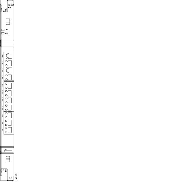
2.3.5 MS-ISC-100T Card
The Multishelf Internal Switch Card (MS-ISC-100T) is an Ethernet switch used to implement the multishelf LAN. It connects the node controller shelf to the network and to subtending shelves. The MS-ISC-100T must always be equipped on the node controller shelf; it cannot be provisioned on a subtending controller shelf.
The recommended configuration is to implement LAN redundancy using two MS-ISC-100T cards: one switch is connected to the Ethernet front panel port of the TCC2/TCC2P card in Slot 7, and the other switch is connected to the Ethernet front panel port of the TCC2/TCC2P card in Slot 11. The Ethernet configuration of the MS-ISC-100T card is part of the software package and is automatically loaded. The MS-ISC-100T card operates in Slots 1 to 6 and 12 to 17 on the node controller shelf; the recommended slots are Slot 6 and Slot 12.
Table 2-16 lists the MS-ISC-100T port assignments.
Figure 2-15 shows the card faceplate.
Caution
Figure 2-15 MS-ISC-100T Faceplate
2.3.5.1 MS-ISC-100T Card-Level Indicators
The MS-ISC-100T card supports two card-level LED indicators. The card-level indicators are described in Table 2-17.
2.4 Front Mount Electrical Connections
This section describes the MIC-A/P and MIC-C/T/P FMECs, which provide power, external alarm, and timing connections for the ONS 15454 ETSI shelf.
2.4.1 MIC-A/P FMEC
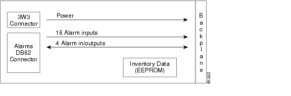
The MIC-A/P FMEC provides connection for the BATTERY B input, one of the two possible redundant power supply inputs. It also provides connection for eight alarm outputs (coming from the TCC2/TCC2P card), sixteen alarm inputs, and four configurable alarm inputs/outputs. Its position is in Slot 23 in the center of the subrack Electrical Facility Connection Assembly (EFCA) area.
The MIC-A/P FMEC has the following features:
•
•
•
•
•
For proper system operation, both the MIC-A/P and MIC-C/T/P FMECs must be installed in the ONS 15454 ETSI shelf. Figure 2-16 shows the MIC-A/P faceplate.
Figure 2-16 MIC-A/P Faceplate
Figure 2-17 shows a block diagram of the MIC-A/P.
Figure 2-17 MIC-A/P Block Diagram
Table 2-18 shows the alarm interface pinouts on the MIC-A/P DB-62 connector.
2.4.2 MIC-C/T/P FMEC
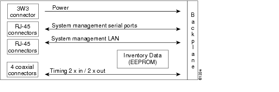
The MIC-C/T/P FMEC provides connection for the BATTERY A input, one of the two possible redundant power supply inputs. It also provides connection for system management serial port, system management LAN port, modem port (for future use), and system timing inputs and outputs. Install the MIC-C/T/P in Slot 24.
The MIC-C/T/P FMEC has the following features:
•
•
•
•
•
•
For proper system operation, both the MIC-A/P and MIC-C/T/P FMECs must be installed in the shelf.
Figure 2-18 shows the MIC-C/T/P FMEC faceplate.
Figure 2-18 MIC-C/T/P Faceplate
Figure 2-19 shows a block diagram of the MIC-C/T/P.
Figure 2-19 MIC-C/T/P Block Diagram
The MIC-C/T/P FMEC has one pair of LEDs located on the RJ45 LAN connector. The green LED is on when a link is present, and the amber LED is on when data is being transferred.
2.5 Optical Service Channel Cards
This section describes the optical service channel cards. An optical service channel (OSC) is a bidirectional channel connecting two adjacent nodes in a DWDM ring. For every DWDM node (except terminal nodes), two different OSC terminations are present, one for the west side and another for the east side. The channel transports OSC overhead that is used to manage ONS 15454 DWDM networks. An OSC signal uses the 1510-nm wavelength and does not affect client traffic. The primary purpose of this channel is to carry clock synchronization and orderwire channel communications for the DWDM network. It also provides transparent links between each node in the network. The OSC is an OC-3/STM-1 formatted signal.
There are two versions of the OSC modules: the OSCM, and the OSC-CSM, which contains the OSC wavelength combiner and separator component in addition to the OSC module.
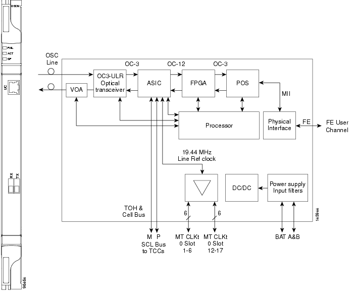
2.5.1 OSCM Card
The OSCM card is used in amplified nodes that include the OPT-BST, OPT-BST-E, or OPT-BST-L booster amplifier. The OPT-BST, OPT-BST-E, and OPT-BST-L cards include the required OSC wavelength combiner and separator component. The OSCM cannot be used in nodes where you use OC-N/STM-N cards, electrical cards, or cross-connect cards. The OSCM uses Slots 8 and 10, which are also cross-connect card slots.
The OSCM supports the following features:
•
•
•
•
•
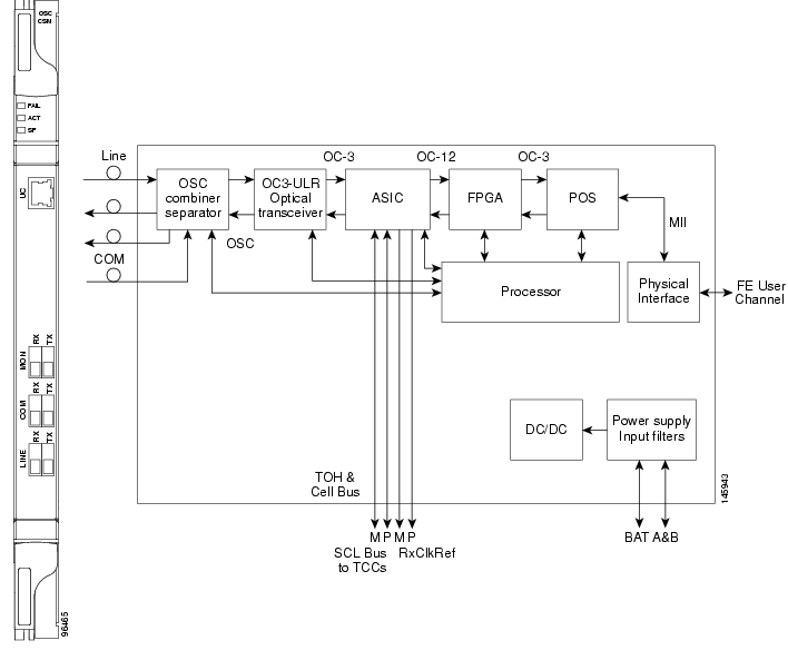
The OC-3/STM-1 section data communications channel (SDCC or RS-DCC) overhead bytes are used for network communications. An optical transceiver terminates the OC-3/STM-1, then it is regenerated and converted into an electrical signal. The SDCC or RS-DCC bytes are forwarded to the active and standby TCC2/TCC2P cards for processing through the system communication link (SCL) bus on the backplane. Orderwire bytes (E1, E2, F1) are also forwarded via the SCL bus to the TCC2/TCC2P for forwarding to the AIC-I card.
The payload portion of the OC-3/STM-1 is used to carry the fast Ethernet UC. The frame is sent to a packet-over-SONET/SDH (POS) processing block that extracts the Ethernet packets and makes them available at the RJ-45 connector.
The OSCM distributes the reference clock information by removing it from the incoming OC-3/STM-1 signal and then sending it to the DWDM cards. The DWDM cards then forward the clock information to the active and standby TCC2/TCC2P cards.
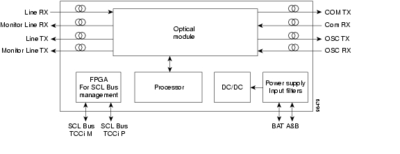
Figure 2-20 shows the OSCM card faceplate and block diagram.
Figure 2-20 OSCM Card Faceplate
For information on safety labels for the card, see the "Class 1 Laser Product Cards" section.
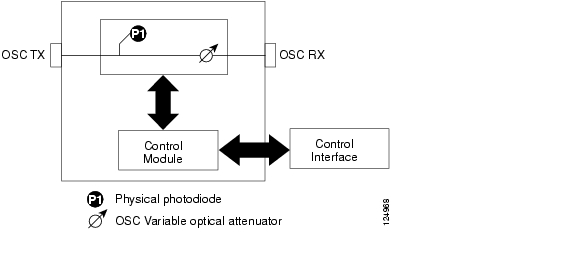
Figure 2-21 shows the block diagram of the variable optical attenuator (VOA) within the OSCM.
Figure 2-21 OSCM VOA Optical Module Functional Block Diagram
2.5.1.1 Power Monitoring
Physical photodiode P1 monitors the power for the OSCM card. The returned power level value is calibrated to the OSC TX port ( Table 2-19).
Table 2-19 OSCM VOA Port Calibration
P1
Output OSC
OSC TX
2.5.1.2 OSCM Card-Level Indicators
The OSCM card has three card-level LED indicators, described in Table 2-20.
2.5.1.3 OSCM Port-Level Indicators
You can find the status of the card ports using the LCD screen on the ONS 15454 fan-tray assembly. Use the LCD to view the status of any port or card slot; the screen displays the number and severity of alarms for a given port or slot. The OSCM has one OC-3/STM-1 optical port located on the faceplate. One long-reach OSC transmits and receives the OSC to and from another DWDM node. Both DCN data and FE payload are carried on this link.
2.5.2 OSC-CSM Card
The OSC-CSM card is used in unamplified nodes. This means that the booster amplifier with the OSC wavelength combiner and separator is not required for OSC-CSM operation. The OSC-CSM can be installed in Slots 1 to 6 and 12 to 17. To operate in hybrid mode, the OSC-CSM cards must be accompanied by cross-connect cards. The cross-connect cards enable functionality on the OC-N/STM-N cards and electrical cards.
The OSC-CSM supports the following features:
•
•
•
•
•
•
•
•
•
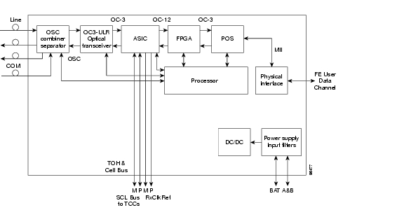
The WDM signal coming from the line is passed through the OSC combiner and separator, where the OSC signal is extracted from the WDM signal. The WDM signal is sent along with the remaining channels to the COM port (label on the front panel) for routing to the OADM or amplifier units, while the OSC signal is sent to an optical transceiver.
The OSC is an OC-3/STM-1 formatted signal. The OC-3/STM-1 SDCC or RS-DCC overhead bytes are used for network communications. An optical transceiver terminates the OC-3/STM-1, and then it is regenerated and converted into an electrical signal. The SDCC or RS-DCC bytes are forwarded to the active and standby TCC2/TCC2P cards for processing via the SCL bus on the backplane. Orderwire bytes (E1, E2, F1) are also forwarded via the SCL bus to the TCC2/TCC2P for forwarding to the AIC-I card.
The payload portion of the OC-3/STM-1 is used to carry the fast Ethernet UC. The frame is sent to a POS processing block that extracts the Ethernet packets and makes them available at the RJ-45 front panel connector.
The OSC-CSM distributes the reference clock information by removing it from the incoming OC-3/STM-1 signal and then sending it to the active and standby TCC2/TCC2P cards. The clock distribution is different from the OSCM card because the OSC-CSM does not use Slot 8 or 10 (cross-connect card slots).
Note
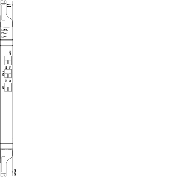
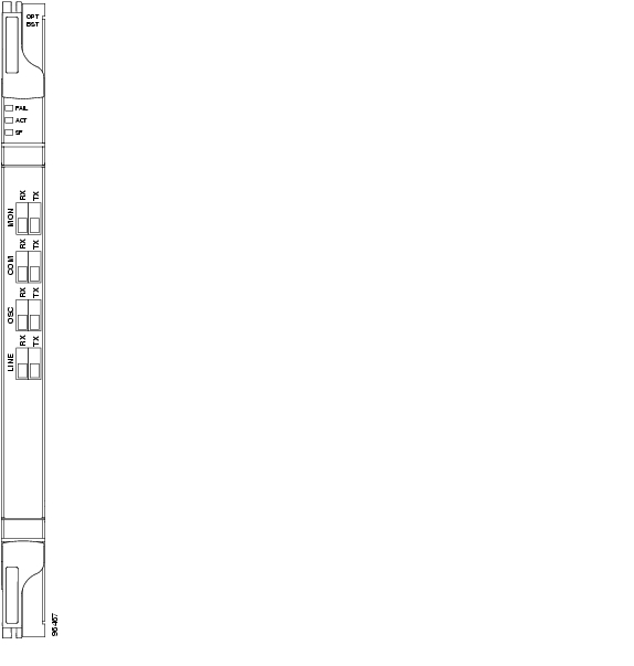
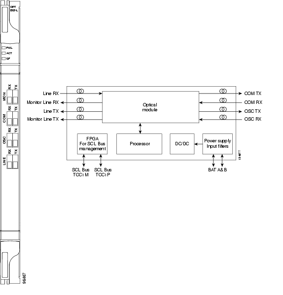
Figure 2-22 shows the OSC-CSM faceplate.
Figure 2-22 OSC-CSM Faceplate
For information on safety labels for the card, see the "Class 1 Laser Product Cards" section.
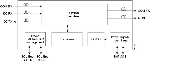
Figure 2-23 shows a block diagram of the OSC-CSM card.
Figure 2-23 OSC-CSM Block Diagram
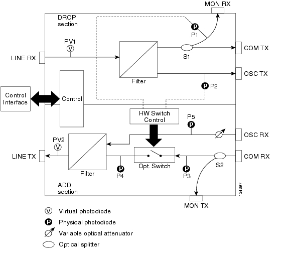
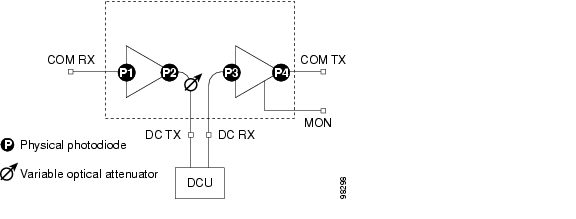
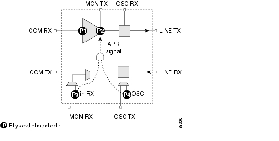
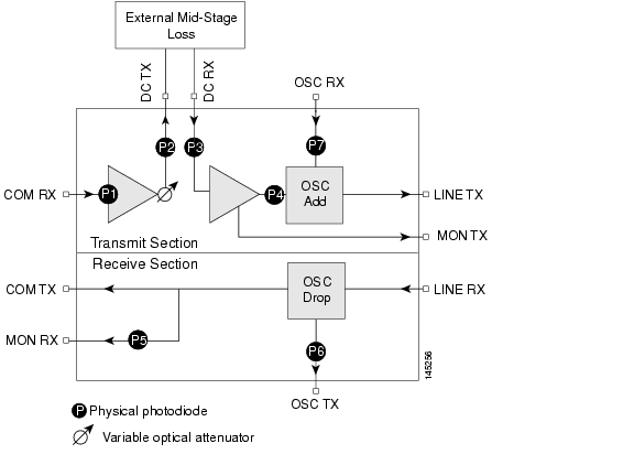
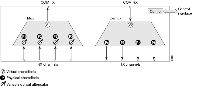
Figure 2-24 shows the OSC-CSM optical module functional block diagram.
Figure 2-24 OSC-CSM Optical Module Functional Block Diagram
2.5.2.1 Power Monitoring
Physical photodiodes P1, P2, P3, and P5 monitor the power for the OSC-CSM card. Their function is as follows:
•
•
•
The returned power level values are calibrated to the ports as shown in Table 2-21.
Table 2-21 OSC-CSM Port Calibration
P1
Out Com
LINE RX
P2
Input OSC
LINE RX
P3
In Com
COM RX
P5
Output Osc
LINE TX
2.5.2.2 OSC-CSM Card-Level Indicators
The OSC-CSM card has three card-level LED indicators, described in Table 2-22.
2.5.2.3 OSC-CSM Port-Level Indicators
You can find the status of the card ports using the LCD screen on the ONS 15454 fan-tray assembly. Use the LCD to view the status of any port or card slot; the screen displays the number and severity of alarms for a given port or slot. The OSC-CSM has a OC3 port and three other sets of ports located on the faceplate.
2.6 Optical Amplifier Cards
This section describes the optical amplifier cards. Optical amplifiers are used in amplified nodes, such as hub nodes, amplified OADM nodes, and line amplifier nodes. There are five forms of amplifiers, the Optical Preamplifier (OPT-PRE), the Optical Booster (OPT-BST) amplifier, the Optical Booster Enhanced (OPT-BST-E) amplifier, the Optical Booster L-Band amplifier (OPT-BST-L), and the Optical L-Band preamplifier (OPT-AMP-L).
Note
The optical amplifier card architecture includes an optical plug-in module with a controller that manages optical power, laser current, and temperature control loops. The amplifier also manages communication with the TCC2/TCC2P card, and operation, administration, maintenance, and provisioning (OAM&P) functions such as provisioning, controls, and alarms.
Optical amplifiers have a linear power feature that enables them to be kept in the constant gain mode if the gain is less than 28 dB. However, for longer span solutions it is necessary to place the amplifier in constant power mode. In constant power mode, automatic power control (APC) requirements change. This is because span loss degradation does not affect the system and amplifiers are not able to automatically modify the output power for variations in the number of channels when provisioning changes and a failure occurs.
2.6.1 OPT-PRE Amplifier
This section describes the OPT-PRE amplifier card. The OPT-PRE is designed to support 64 channels at 50-GHz channel spacing, but is currently limited to 32 channels at 100 GHz. The OPT-PRE is a C-band DWDM, two-stage erbium-doped fiber amplifier (EDFA) with mid-amplifier loss (MAL) for allocation to a DCU. To control the gain tilt, the OPT-PRE is equipped with a built-in VOA. The VOA can also be used to pad the DCU to a reference value. You can install the OPT-PRE in Slots 1 to 6 and 12 to 17.
The OPT-PRE features:
•
•
•
•
•
•
•
•
•
•
•
Note
Figure 2-25 shows the OPT-PRE amplifier faceplate.
Figure 2-25 OPT-PRE Faceplate
For information on safety labels for the card, see the "Class 1M Laser Product Cards" section.
Figure 2-26 shows a block diagram of the OPT-PRE card.
Figure 2-26 OPT-PRE Block Diagram
Figure 2-27 shows the OPT-PRE optical module functional block diagram.
Figure 2-27 OPT-PRE Optical Module Functional Block Diagram
2.6.1.1 Power Monitoring
Physical photodiodes P1, P2, P3, and P4 monitor the power for the OPT-PRE card. The returned power level values are calibrated to the ports as shown in Table 2-23.
Table 2-23 OPT-PRE Port Calibration
P1
Input Com
COM RX
P2
Output DC
DC TX
P3
Input DC
DC RX
P4
Output COM (Total Output)
COM TX
Output COM (Signal Output)
2.6.1.2 OPT-PRE Amplifier Card-Level Indicators
The OPT-PRE amplifier has three card-level LED indicators, described in Table 2-24.
2.6.1.3 OPT-PRE Port-Level Indicators
You can find the status of the card ports using the LCD screen on the ONS 15454 fan-tray assembly. Use the LCD to view the status of any port or card slot; the screen displays the number and severity of alarms for a given port or slot. The OPT-PRE amplifier has five optical ports located on the faceplate. MON is the output monitor port. COM RX (receive) is the input signal port. COM TX (transmit) is the output signal port. DC RX is the MAL input signal port. DC TX is the MAL output signal port.
2.6.2 OPT-BST Amplifier Card
This section describes the OPT-BST amplifier card. The OPT-BST gain range is 5 to 20 dB in constant gain mode and output power mode. The OPT-BST is designed to support 64 channels at 50-GHz channel spacing, but currently is limited to 32 channels at 100 GHz. The OPT-BST is a C-band DWDM EDFA with OSC add-and-drop capability. When an ONS 15454 has an OPT-BST installed, it is only necessary to have the OSCM to process the OSC. You can install the OPT-BST in Slots 1 to 6 and 12 to 17. To control the gain tilt, the OPT-BST is equipped with a built-in VOA.
The OPT-BST features include:
•
•
•
•
•
•
•
•
•
•
Note
Figure 2-28 shows the OPT-BST amplifier faceplate.
Figure 2-28 OPT-BST Faceplate
For information on safety labels for the card, see the "Class 1M Laser Product Cards" section.
Figure 2-29 shows a block diagram of the OPT-BST card.
Figure 2-29 OPT-BST Block Diagram
Figure 2-30 shows the OPT-BST optical module functional block diagram.
Figure 2-30 OPT-BST Optical Module Functional Block Diagram
2.6.2.1 Power Monitoring
Physical photodiodes P1, P2, P3, and P4 monitor the power for the OPT-BST card. The returned power level values are calibrated to the ports as shown in Table 2-25.
2.6.2.2 OPT-BST Amplifier Card-Level Indicators
The OPT-BST amplifier has three card-level LED indicators, described in Table 2-26.
2.6.2.3 OPT-BST Port-Level Indicators
You can find the status of the card ports using the LCD screen on the ONS 15454 fan-tray assembly. Use the LCD to view the status of any port or card slot; the screen displays the number and severity of alarms for a given port or slot. The OPT-BST amplifier has eight optical ports located on the faceplate. MON RX is the output monitor port (receive section). MON TX is the output monitor port. COM RX is the input signal port. LINE TX is the output signal port. LINE RX is the input signal port (receive section). COM TX is the output signal port (receive section). OSC RX is the OSC add input port. OSC TX is the OSC drop output port.
2.6.3 OPT-BST-E Amplifier Card
This section describes the OPT-BST-E amplifier card, which is a gain-enhanced version of the OPT-BST card. The OPT-BST-E gain range is 8 to 23 dBm with the tilt managed at 0 dBm in constant gain mode and output power mode. However, an enhanced gain range of 23 to 26 dBm is available with the tilt unmanaged. See Appendix A, "Hardware Specifications" for detailed specification information. The OPT-BST-E is designed to support 64 channels at 50-GHz channel spacing, but currently is limited to 32 channels at 100 GHz. The OPT-BST-E is a C-band DWDM EDFA with OSC add-and-drop capability. When an ONS 15454 has an OPT-BST-E installed, it is only necessary to have the OSCM to process the OSC. You can install the OPT-BST-E in Slots 1 to 6 and 12 to 17. To control the gain tilt, the OPT-BST-E is equipped with a built-in VOA.
The OPT-BST-E features include:
•
•
•
•
•
•
•
•
•
•
•
Note
Figure 2-31 shows the OPT-BST-E amplifier faceplate.
Figure 2-31 OPT-BST-E Faceplate
For information on safety labels for the card, see the "Class 1M Laser Product Cards" section.
Figure 2-32 shows a block diagram of the OPT-BST-E card.
Figure 2-32 OPT-BST-E Block Diagram
Figure 2-33 shows the OPT-BST-E optical module functional block diagram.
Figure 2-33 OPT-BST-E Optical Module Functional Block Diagram
2.6.3.1 Power Monitoring
Physical photodiodes P1, P2, P3, and P4 monitor the power for the OPT-BST-E card. The returned power level values are calibrated to the ports as shown in Table 2-27.
2.6.3.2 OPT-BST-E Amplifier Card-Level Indicators
The OPT-BST-E amplifier has three card-level LED indicators, described in Table 2-28.
2.6.3.3 OPT-BST-E Port-Level Indicators
You can find the status of the card ports using the LCD screen on the ONS 15454 fan-tray assembly. Use the LCD to view the status of any port or card slot; the screen displays the number and severity of alarms for a given port or slot. The OPT-BST-E amplifier has eight optical ports located on the faceplate. MON RX is the output monitor port (receive section). MON TX is the output monitor port. COM RX is the input signal port. LINE TX is the output signal port. LINE RX is the input signal port (receive section). COM TX is the output signal port (receive section). OSC RX is the OSC add input port. OSC TX is the OSC drop output port.
2.6.4 OPT-BST-L Amplifier Card
This section describes the OPT-BST-L amplifier card. The OPT-BST-L standard gain range is 8 to 20 dB in the controllable gain tilt mode, and 20 to 27 dB in the uncontrolled gain tilt mode. The OPT-BST-L is designed to support 64 channels at 50-GHz channel spacing, but currently is limited to 32 channels at 100 GHz spacing. The OPT-BST-L is an L-band DWDM EDFA with OSC add-and-drop capability. The card is particularly well suited for use in networks that employ dispersion shifted (DS) fiber or SMF-28 single-mode fiber. When an ONS 15454 has an OPT-BST-L installed, it is only necessary to have the OSCM to process the OSC. You can install the OPT-BST-L in Slots 1 to 6 and 12 to 17. To control the gain tilt, the OPT-BST-L is equipped with a built-in VOA.
The OPT-BST-L features include:
•
•
•
•
•
•
•
•
•
•
Note
Figure 2-34 shows the OPT-BST-L amplifier faceplate and block diagram.
Figure 2-34 OPT-BST-L Faceplate
For information on safety labels for the card, see the "Class 1M Laser Product Cards" section.
Figure 2-35 shows the OPT-BST-L optical module functional block diagram.
Figure 2-35 OPT-BST-L Optical Module Functional Block Diagram
2.6.4.1 Power Monitoring
Physical photodiodes P1, P2, P3, P4, and P5 monitor the power for the OPT-BST-L card. The returned power level values are calibrated to the ports as shown in Table 2-29.
2.6.4.2 OPT-BST-L Amplifier Card-Level Indicators
The OPT-BST-L amplifier has three card-level LED indicators, described in Table 2-30.
2.6.4.3 OPT-BST-L Port-Level Indicators
You can find the status of the card ports using the LCD screen on the ONS 15454 fan-tray assembly. Use the LCD to view the status of any port or card slot; the screen displays the number and severity of alarms for a given port or slot. The OPT-BST-L amplifier has eight optical ports located on the faceplate. MON RX is the output monitor port (receive section). MON TX is the output monitor port. COM RX is the input signal port. LINE TX is the output signal port. LINE RX is the input signal port (receive section). COM TX is the output signal port (receive section). OSC RX is the OSC add input port. OSC TX is the OSC drop output port.
2.6.5 OPT-AMP-L Card
This section describes the OPT-AMP-L preamplifier card. The OPT-AMP-L is an L-band DWDM optical amplifier module consisting of a two-stage EDFA with mid-stage access loss (MSL) for an external DCU and OSC add-and-drop capability. Using CTC, the card is provisionable as a preamplifier (OPT-PRE) or booster amplifier (OPT-BST), and is well suited for use in networks that employ DS fiber or SMF-28 single-mode fiber. The amplifier can operate up to 64 optical transmission channels at a channel spacing of 50 GHz in the wavelength range from 1570 nm to 1605 nm.
The OPT-AMP-L is able to achieve a maximum signal power of 20 dBm throughout the gain and MSL ranges. The amplifier has a variable gain range that is settable from 12 to 24 dBm in the standard gain range and from 24 dBm to 35 dBm with uncontrolled gain tilt. It also provides up to 12 dBm MSL for an external DCU.
When an ONS 15454 has an OPT-AMP-L installed, it is only necessary to have the OSCM to process the OSC. You can install the two-slot OPT-AMP-L in Slots 1 to 6 and 12 to 17. To control the gain tilt, the OPT-AMP-L is equipped with a built-in VOA.
The OPT-AMP-L has the following features:
•
•
•
•
•
•
•
•
•
•
•
•
Note
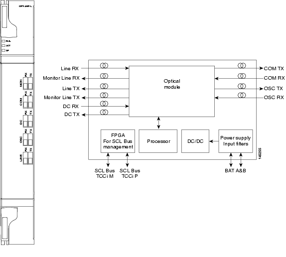
Figure 2-36 shows the OPT-AMP-L amplifier faceplate and block diagram.
Figure 2-36 OPT-AMP-L Faceplate
For information on safety labels for the card, see the "Class 1M Laser Product Cards" section.
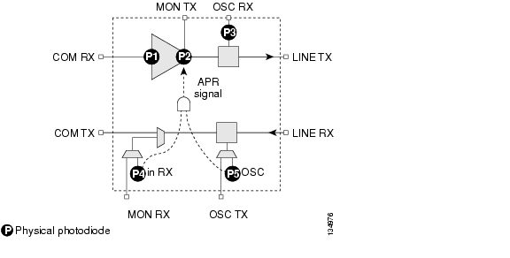
Figure 2-37 shows the OPT-AMP-L optical module functional block diagram.
Figure 2-37 OPT-AMP-L Optical Module Functional Block Diagram
2.6.5.1 Power Monitoring
Physical photodiodes P1 through P7 monitor the power for the OPT-AMP-L card. The returned power level values are calibrated to the ports as shown in Table 2-31.
2.6.5.2 OPT-AMP-L Amplifier Card-Level Indicators
The OPT-AMP-L amplifier has three card-level LED indicators, described in Table 2-32.
2.6.5.3 OPT-AMP-L Port-Level Indicators
You can find the status of the card ports using the LCD screen on the ONS 15454 fan-tray assembly. Use the LCD to view the status of any port or card slot; the screen displays the number and severity of alarms for a given port or slot. The OPT-AMP-L amplifier has ten optical ports located on the faceplate. MON RX is the output monitor port (receive section). MON TX is the output monitor port. COM RX is the input signal port. LINE TX is the output signal port. LINE RX is the input signal port (receive section). COM TX is the output signal port (receive section). OSC RX is the OSC add input port. OSC TX is the OSC drop output port. DC TX is the output signal to the DCU, and DC RX is the input signal from the DCU.
2.7 Multiplexer and Demultiplexer Cards
This section describes the multiplexer and demultiplexer cards.
2.7.1 32MUX-O Card
The 32-Channel Multiplexer (32MUX-O) card multiplexes 32 100-GHz-spaced channels identified in the channel plan. The 32MUX-O card takes up two slots in an ONS 15454 and can be installed in Slots 1 to 5 and 12 to 16.
The 32MUX-O features include:
•
•
•
An additional optical monitoring port with 1:99 splitting ratio is available.
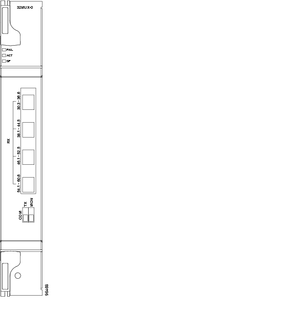
Figure 2-38 shows the 32MUX-O faceplate.
Figure 2-38 32MUX-O Faceplate
For information on safety labels for the card, see the "Class 1 Laser Product Cards" section.
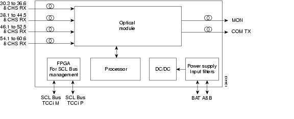
Figure 2-39 shows a block diagram of the 32MUX-O card.
Figure 2-39 32MUX-O Block Diagram
The 32MUX-O card has four receive connectors that accept multifiber push-on (MPO) cables on its front panel for the client input interfaces. MPO cables break out into eight separate cables. The 32MUX-O card also has two LC-PC-II optical connectors, one for the main output and the other for the monitor port.
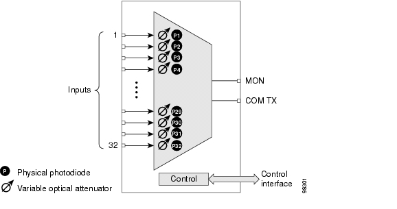
Figure 2-40 shows the 32MUX-O optical module functional block diagram.
Figure 2-40 32MUX-O Optical Module Functional Block Diagram
2.7.1.1 Channel Plan
The 32MUX-O is typically used in hub nodes and provides the multiplexing of 32 channels, spaced at 100 GHz, into one fiber before their amplification and transmission along the line. The channel plan is shown in Table 2-33.
Table 2-33 32MUX-O Channel Plan
1
30.3
195.9
1530.33
2
31.2
195.8
1531.12
3
31.9
195.7
1531.90
4
32.6
195.6
1532.68
5
34.2
195.4
1534.25
6
35.0
195.3
1535.04
7
35.8
195.2
1535.82
8
36.6
195.1
1536.61
9
38.1
194.9
1538.19
10
38.9
194.8
1538.98
11
39.7
194.7
1539.77
12
40.5
194.6
1540.56
13
42.1
194.4
1542.14
14
42.9
194.3
1542.94
15
43.7
194.2
1543.73
16
44.5
194.1
1544.53
17
46.1
193.9
1546.12
18
46.9
193.8
1546.92
19
47.7
193.7
1547.72
20
48.5
193.6
1548.51
21
50.1
193.4
1550.12
22
50.9
193.3
1550.92
23
51.7
193.2
1551.72
24
52.5
193.1
1552.52
25
54.1
192.9
1554.13
26
54.9
192.8
1554.94
27
55.7
192.7
1555.75
28
56.5
192.6
1556.55
29
58.1
192.4
1558.17
30
58.9
192.3
1558.98
31
59.7
192.2
1559.79
32
60.6
192.1
1560.61
1 The Channel Number column is only for reference purposes. The channel ID is consistent with the ONS 15454 and is used in card identification.
2.7.1.2 Power Monitoring
Physical photodiodes P1 through P32 monitor the power for the 32MUX-O card. The returned power level values are calibrated to the ports as shown in Table 2-34.
2.7.1.3 32MUX-O Card-Level Indicators
The 32MUX-O card has three card-level LED indicators, described in Table 2-35.
2.7.1.4 32MUX-O Port-Level Indicators
You can find the status of the card ports using the LCD screen on the ONS 15454 fan-tray assembly. Use the LCD to view the status of any port or card slot; the screen displays the number and severity of alarms for a given port or slot. The 32MUX-O card has five sets of ports located on the faceplate.
COM TX is the line output. COM MON is the optical monitoring port. The xx.x to yy.y RX ports represent the four groups of eight channels ranging from wavelength xx.x to wavelength yy.y, according to the channel plan.
2.7.2 32DMX-O Card
The 32-Channel Demultiplexer (32DMX-O) card demultiplexes 32 100-GHz-spaced channels identified in the channel plan. The 32DMX-O takes up two slots in an ONS 15454 and can be installed in Slots 1 to 5 and 12 to 16.
The 32DMX-O features include:
•
•
•
Note
•
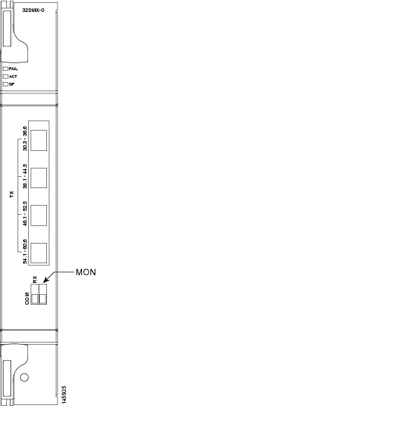
Figure 2-41 shows the 32DMX-O card faceplate.
Figure 2-41 32DMX-O Faceplate
For information on safety labels for the card, see the "Class 1M Laser Product Cards" section.
Figure 2-42 shows a block diagram of the 32DMX-O card.
Figure 2-42 32DMX-O Block Diagram
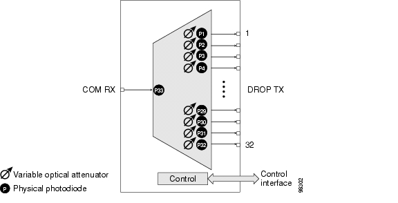
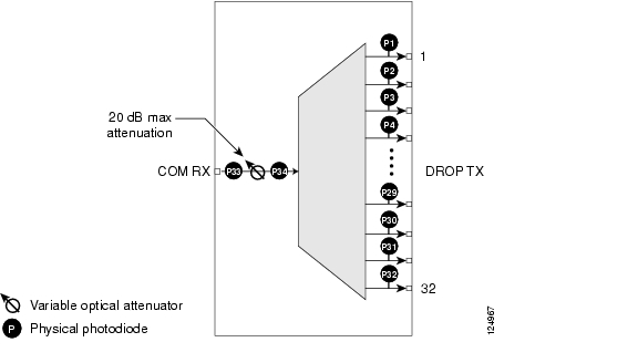
Figure 2-43 shows the 32DMX-O optical module functional block diagram.
Figure 2-43 32DMX-O Optical Module Functional Block Diagram
2.7.2.1 Power Monitoring
Physical photodiodes P1 through P33 monitor the power for the 32DMX-O card. The returned power level values are calibrated to the ports as shown in Table 2-36.
Table 2-36 32DMX-O Port Calibration
P1-P32
DROP
DROP TX
P33
INPUT COM
COM RX
2.7.2.2 32DMX-O Card-Level Indicators
The 32DMX-O card has three card-level LED indicators, described in Table 2-37.
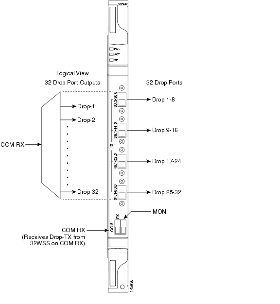
2.7.2.3 32DMX-O Port-Level Indicators
You can find the status of the card ports using the LCD screen on the ONS 15454 fan-tray assembly. Use the LCD to view the status of any port or card slot; the screen displays the number and severity of alarms for a given port or slot. The 32DMX-O card has five sets of ports located on the faceplate. MON is the output monitor port. COM RX is the line input. The xx.x to yy.y TX ports represent the four groups of eight channels ranging from wavelength xx.x to wavelength yy.y according to the channel plan.
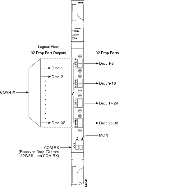
2.7.3 32DMX Card
The 32-Channel Demultiplexer (32DMX) card is a single-slot optical demultiplexer. The card receives an aggregate optical signal on its COM RX port and demultiplexes it into to 32 100-GHz-spaced channels. The 32DMX card can be installed in Slots 1 to 6 and in Slots 12 to 17.
The 32DMX includes these high-level features:
•
•
•
Figure 2-44 shows the 32DMX card front panel and the basic traffic flow through the ports.
Figure 2-44 32DMX Faceplate and Ports
For information on safety labels for the card, see the "Class 1M Laser Product Cards" section.
The 32DMX front panel has connectors for 32 DROP TX ports. These ports are connected using four 8-fiber MPO ribbon connectors. The incoming optical signal to the demultiplexer comes into the COM RX port. This input port is connected using a single LC duplex optical connector.
A block diagram of the 32DMX card is shown in Figure 2-45.
Figure 2-45 32DMX Block Diagram
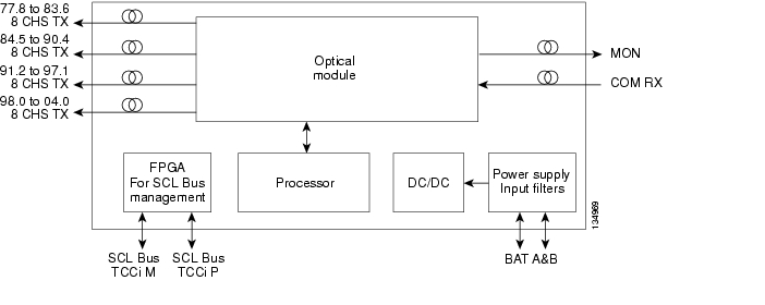
Figure 2-46 shows the 32DMX optical module functional block diagram.
Figure 2-46 32DMX Optical Module Functional Block Diagram
2.7.3.1 ROADM
The 32DMX card works in conjunction with the 32WSS card to create a software-controlled network element (NE) with ROADM functionality. ROADM functionality requires two 32DMX single-slot cards and two 32WSS double-slot cards (six slots total in the ONS 15454 chassis).
Equipped with ROADM functionality, ONS 15454 MSTP nodes can be configured at the optical channel level using CTC, Cisco MetroPlanner, and Cisco Transport Manager (CTM). Both the 32DMX card and 32WSS cards utilize planar lightwave circuit (PLC) technology to perform wavelength-level processing.
2.7.3.2 Power Monitoring
Physical photodiodes P1 through P33 monitor the power for the 32DMX card. The returned power level values are calibrated to the ports as shown in Table 2-38.
Table 2-38 32DMX Port Calibration
P1-P32
DROP
DROP TX
P33
INPUT COM
COM RX
2.7.3.3 32DMX Card-Level Indicators
Table 2-39 describes the three card-level LED indicators on the 32DMX card.
2.7.3.4 32DMX Port-Level Indicators
You can find the status of the 32DMX ports using the LCD screen on the ONS 15454 fan-tray assembly. Use the LCD to view the status of any port or card slot; the screen displays the number and severity of alarms for a given port or slot.
The 32DMX card has five ports located on the faceplate. The port labeled COM RX is the line input (it typically receives DROP TX from the 32WSS module). The TX ports are 32 drop ports. The connectors provide four groups of eight channels ranging from wavelength xx.x to wavelength yy.y according to the channel plan.
2.7.4 32DMX-L Card
The 32-Channel Demultiplexer L-Band card (32DMX-L) is a single-slot optical demultiplexer. The card receives an aggregate optical signal on its COM RX port and demultiplexes it into to 32 100-GHz-spaced channels. The 32DMX-L card is particularly well suited for use in networks that employ DS fiber or SMF-28 single-mode fiber. The 32DMX-L card can be installed in Slots 1 to 6 and in Slots 12 to 17.
The 32DMX-L card includes these high-level features:
•
•
•
Figure 2-47 shows the 32DMX-L card front panel and the basic traffic flow through the ports.
Figure 2-47 32DMX-L Faceplate and Ports
For information on safety labels for the card, see the "Class 1M Laser Product Cards" section.
The 32DMX-L front panel has connectors for 32 DROP TX ports. These ports are connected using four 8-fiber MPO ribbon connectors. The incoming optical signal to the demultiplexer comes into COM RX. This input port is connected using a single LC duplex optical connector.
A block diagram of the 32DMX-L card is shown in Figure 2-45.
Figure 2-48 32DMX-L Block Diagram
Figure 2-46 shows the 32DMX-L optical module functional block diagram.
Figure 2-49 32DMX-L Optical Module Functional Block Diagram
2.7.4.1 ROADM
The 32DMX-L card works in conjunction with the 32WSS-L card to create a software-controlled NE with ROADM functionality. ROADM functionality requires two 32DMX-L single-slot cards and two 32WSS-L double-slot cards (six slots total in the ONS 15454 chassis).
Equipped with ROADM functionality, ONS 15454 MSTP nodes can be configured at the optical channel level using CTC, Cisco MetroPlanner, and CTM. Both the 32DMX-L card and 32WSS-L cards utilize PLC technology to perform wavelength-level processing.
2.7.4.2 Power Monitoring
Physical photodiodes P1 through P33 monitor the power for the 32DMX-L card. The returned power level values are calibrated to the ports as shown in Table 2-38.
Table 2-40 32DMX-L Port Calibration
P1-P32
DROP
DROP TX
P33
INPUT COM
COM RX
2.7.4.3 32DMX-L Card-Level Indicators
Table 2-39 describes the three card-level LED indicators on the 32DMX-L card.
2.7.4.4 32DMX-L Port-Level Indicators
You can find the status of the 32DMX-L ports using the LCD screen on the ONS 15454 fan-tray assembly. Use the LCD to view the status of any port or card slot; the screen displays the number and severity of alarms for a given port or slot.
The 32DMX-L card has five ports located on the faceplate. The port labeled COM RX is the line input (it typically receives DROP TX from the 32WSS-L module). The TX ports are 32 drop ports. The connectors provide four groups of eight channels ranging from wavelength xx.x to wavelength yy.y according to the channel plan.
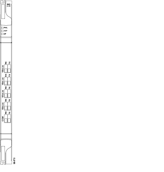
2.7.5 4MD-xx.x Card
The 4-Channel Multiplexer/Demultiplexer (4MD-xx.x) card multiplexes and demultiplexes four 100-GHz-spaced channels identified in the channel plan. The 4MD-xx.x card is designed to be used with band OADMs (both AD-1B-xx.x and AD-4B-xx.x).
The card is bidirectional. The demultiplexer and multiplexer functions are implemented in two different sections of the same card. In this way, the same card can manage signals flowing in opposite directions.
There are eight versions of this card that correspond with the eight sub-bands specified in Table 2-42. The 4MD-xx.x can be installed in Slots 1 to 6 and 12 to 17.
The 4MD-xx.x has the following features implemented inside a plug-in optical module:
•
•
•
•
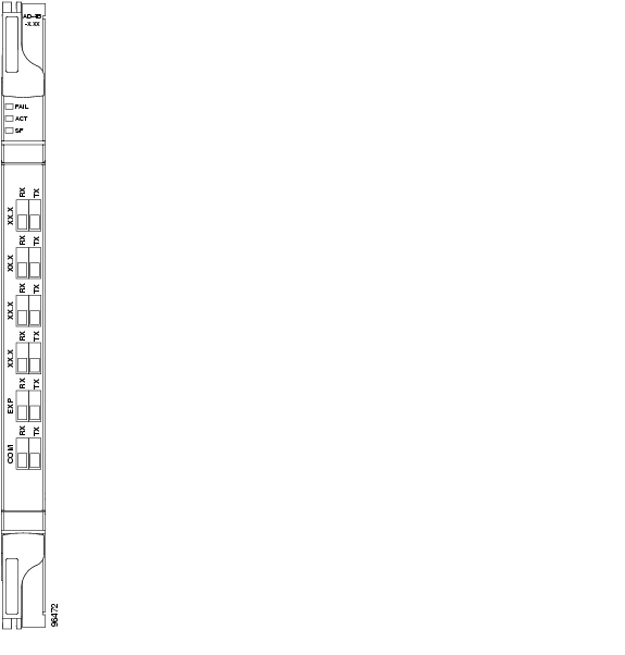
Figure 2-50 shows the 4MD-xx.x faceplate.
Figure 2-50 4MD-xx.x Faceplate
For information on safety labels for the card, see the "Class 1M Laser Product Cards" section.
Figure 2-51 shows a block diagram of the 4MD-xx.x card.
Figure 2-51 4MD-xx.x Block Diagram
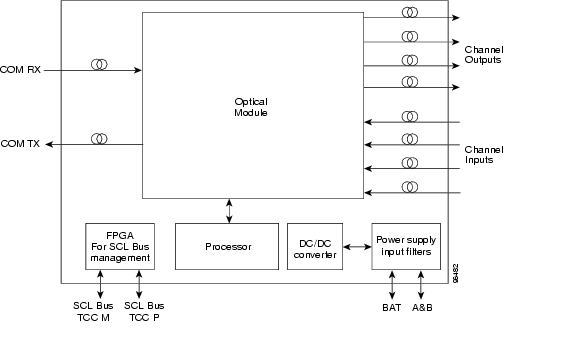
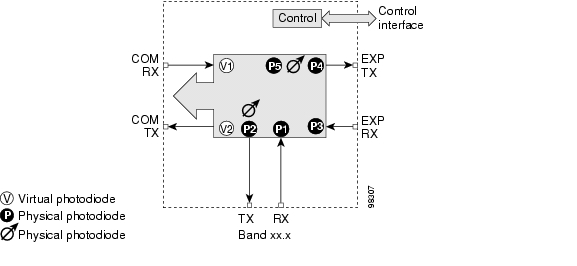
Figure 2-52 shows the 4MD-xx.x optical module functional block diagram.
Figure 2-52 4MD-xx.x Optical Module Functional Block Diagram
The optical module shown in Figure 2-52 is optically passive and consists of a cascade of interferential filters that perform the channel multiplexing and demultiplexing functions.
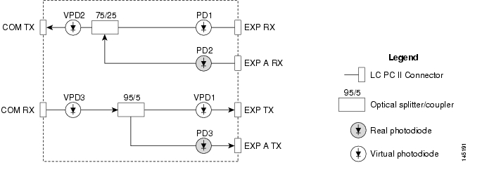
VOAs are present in every input path of the multiplex section in order to regulate the optical power of each multiplexed channel. Some optical input and output ports are monitored by means of photodiodes implemented both for power control and for safety purposes. An internal control manages VOA settings and functionality as well as photodiode detection and alarm thresholds. The power at the main output and input ports is monitored through the use of virtual photodiodes. A virtual photodiode is implemented in the firmware of the plug-in module. This firmware calculates the power on a port, summing the measured values from all single channel ports (and applying the proper path insertion loss) and then providing the TCC2/TCC2P card with the obtained value.
2.7.5.1 Wavelength Pairs
Table 2-42 shows the band IDs and the add/drop channel IDs for the 4MD-xx.x card.
2.7.5.2 Power Monitoring
Physical photodiodes P1 through P8 and virtual photodiodes V1 and V2 monitor the power for the 4MD-xx.x card. The returned power level values are calibrated to the ports as shown in Table 2-43.
Table 2-43 4MD-xx.x Port Calibration
P1-P4
ADD
COM TX
P5-P8
DROP
DROP TX
V1
OUT COM
COM TX
V2
IN COM
COM RX
2.7.5.3 4MD-xx.x Card-Level Indicators
The 4MD-xx.x card has three card-level LED indicators, described in Table 2-44.
2.7.5.4 4MD-xx.x Port-Level Indicators
You can find the status of the card ports using the LCD screen on the ONS 15454 fan-tray assembly. Use the LCD to view the status of any port or card slot; the screen displays the number and severity of alarms for a given port or slot. The 4MD-xx.x card has five sets of ports located on the faceplate. COM RX is the line input. COM TX is the line output. The 15xx.x TX ports represent demultiplexed channel outputs 1 to 4. The 15xx.x RX ports represent multiplexed channel inputs 1 to 4.
2.8 Optical Add/Drop Multiplexer Cards
This section discusses the optical add/drop multiplexer cards.
2.8.1 AD-1C-xx.x Card
The 1-Channel OADM (AD-1C-xx.x) card passively adds or drops one of the 32 channels utilized within the 100-GHz-spacing of the DWDM card system. Thirty-two versions of this card—each designed only for use with one wavelength—are used in the ONS 15454 DWDM system. Each wavelength version of the card has a different part number. The AD-1C-xx.x can be installed in Slots 1 to 6 and 12 to 17.
The AD-1C-xx.x has the following internal features:
•
•
•
•
•
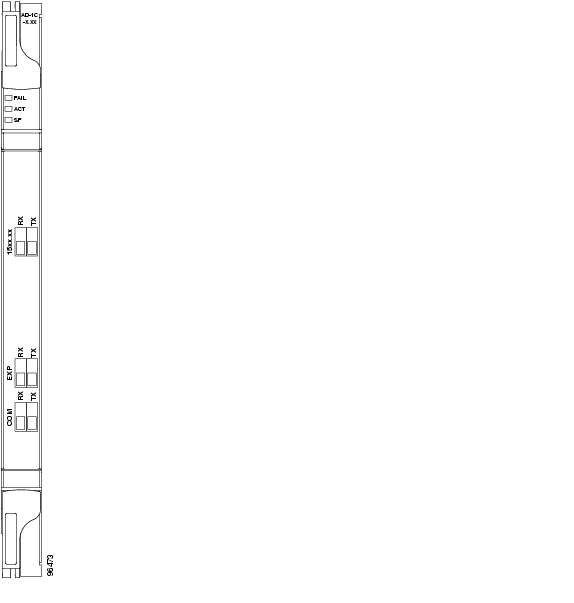
Figure 2-53 shows the AD-1C-xx.x faceplate.
Figure 2-53 AD-1C-xx.x Faceplate
For information on safety labels for the card, see the "Class 1M Laser Product Cards" section.
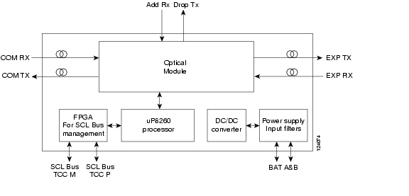
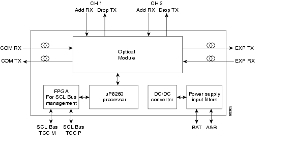
Figure 2-54 shows a block diagram of the AD-1C-xx.x card.
Figure 2-54 AD-1C-xx.x Block Diagram
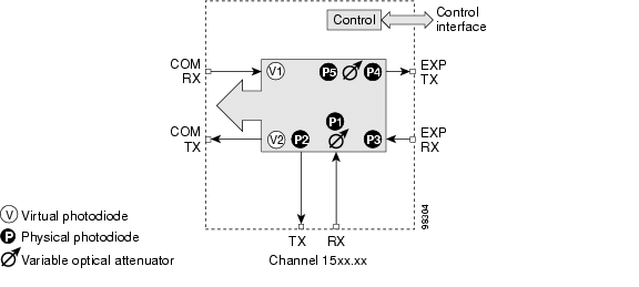
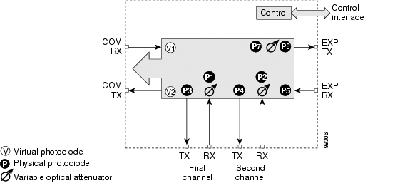
Figure 2-55 shows the AD-1C-xx.x optical module functional block diagram.
Figure 2-55 AD-1C-xx.x Optical Module Functional Block Diagram
2.8.1.1 Power Monitoring
Physical photodiodes P1 through P4 and virtual photodiodes V1 and V2 monitor the power for the AD-1C-xx.x card. The returned power level values are calibrated to the ports as shown in Table 2-45
Table 2-45 AD-1C-xx.x Port Calibration
P1
ADD
COM TX
P2
DROP
DROP TX
P3
IN EXP
EXP RX
P4
OUT EXP
EXP TX
V1
IN COM
COM RX
V2
OUT COM
COM TX
2.8.1.2 AD-1C-xx.x Card-Level Indicators
The AD-1C-xx.x card has three card-level LED indicators, described in Table 2-46.
2.8.1.3 AD-1C-xx.x Port-Level Indicators
You can find the status of the card port using the LCD screen on the ONS 15454 fan-tray assembly. Use the LCD to view the status of any port or card slot; the screen displays the number and severity of alarms for a given port or slot. The AD-1C-xx.x has six LC-PC-II optical ports: two for add/drop channel client input and output, two for express channel input and output, and two for communication.
2.8.2 AD-2C-xx.x Card
The 2-Channel OADM (AD-2C-xx.x) card passively adds or drops two adjacent 100-GHz channels within the same band. Sixteen versions of this card—each designed for use with one pair of wavelengths—are used in the ONS 15454 DWDM system. The card bidirectionally adds and drops in two different sections on the same card to manage signal flow in both directions. Each version of the card has a different part number.
The AD-2C-xx.x has the following features:
•
•
•
•
•
Figure 2-56 shows the AD-2C-xx.x faceplate.
Figure 2-56 AD-2C-xx.x Faceplate
For information on safety labels for the card, see the "Class 1M Laser Product Cards" section.
Figure 2-57 shows a block diagram of the AD-2C-xx.x card.
Figure 2-57 AD-2C-xx.x Block Diagram
Figure 2-58 shows the AD-2C-xx.x optical module functional block diagram.
Figure 2-58 AD-2C-xx.x Optical Module Functional Block Diagram
2.8.2.1 Wavelength Pairs
The AD-2C-xx.x cards are provisioned for the wavelength pairs in Table 2-47. In this table, channel IDs are given rather than wavelengths. To compare channel IDs with the actual wavelengths they represent, see Table 2-6.
2.8.2.2 Power Monitoring
Physical photodiodes P1 through P10 and virtual photodiodes V1 and V2 monitor the power for the AD-2C-xx.x card. The returned power level values are calibrated to the ports as shown in Table 2-48.
Table 2-48 AD-2C-xx.x Port Calibration
P1-P4
ADD
COM TX
P5-P8
DROP
DROP TX
P9
IN EXP
EXP RX
P10
OUT EXP
EXP TX
V1
IN COM
COM RX
V2
OUT COM
COM TX
2.8.2.3 AD-2C-xx.x Card-Level Indicators
The AD-2C-xx.x card has three card-level LED indicators, described in Table 2-49.
2.8.2.4 AD-2C-xx.x Port-Level Indicators
You can find the status of the card port using the LCD screen on the ONS 15454 fan-tray assembly. Use the LCD to view the status of any port or card slot; the screen displays the number and severity of alarms for a given port or slot. The AD-2C-xx.x card has eight LC-PC-II optical ports: four for add/drop channel client input and output, two for express channel input and output, and two for communication.
2.8.3 AD-4C-xx.x Card
The 4-Channel OADM (AD-4C-xx.x) card passively adds or drops all four 100-GHz-spaced channels within the same band. Eight versions of this card—each designed for use with one band of wavelengths—are used in the ONS 15454 DWDM system. The card bidirectionally adds and drops in two different sections on the same card to manage signal flow in both directions. There are eight versions of this card with eight part numbers.
The AD-4C-xx.x has the following features:
•
•
•
•
•
Figure 2-59 shows the AD-4C-xx.x faceplate.
Figure 2-59 AD-4C-xx.x Faceplate
For information on safety labels for the card, see the "Class 1M Laser Product Cards" section.
Figure 2-60 shows a block diagram of the AD-4C-xx.x card.
Figure 2-60 AD-4C-xx.x Block Diagram
Figure 2-61 shows the AD-4C-xx.x optical module functional block diagram.
Figure 2-61 AD-4C-xx.x Optical Module Functional Block Diagram
2.8.3.1 Wavelength Sets
The AD-4C-xx.x cards are provisioned for the sets of four 100-GHz-spaced wavelengths shown Table 2-50.
2.8.3.2 Power Monitoring
Physical photodiodes P1 through P10 and virtual photodiodes V1 and V2 monitor the power for the AD-4C-xx.x card. The returned power level values are calibrated to the ports as shown in Table 2-51.
Table 2-51 AD-4C-xx.x Port Calibration
P1-P4
ADD
COM TX
P5-P8
DROP
DROP TX
P9
IN EXP
EXP RX
P10
OUT EXP
EXP TX
V1
IN COM
COM RX
V2
OUT COM
COM TX
2.8.3.3 AD-4C-xx.x Card-Level Indicators
The AD-4C-xx.x card has three card-level LED indicators, described in Table 2-52.
2.8.3.4 AD-4C-xx.x Port-Level Indicators
You can find the status of the card port using the LCD screen on the ONS 15454 fan-tray assembly. Use the LCD to view the status of any port or card slot; the screen displays the number and severity of alarms for a given port or slot. The AD-4C-xx.x card has 12 LC-PC-II optical ports: eight for add/drop channel client input and output, two for express channel input and output, and two for communication.
2.8.4 AD-1B-xx.x Card
The 1-Band OADM (AD-1B-xx.x) card passively adds or drops a single band of four adjacent 100-GHz-spaced channels. Eight versions of this card with eight different part numbers—each version designed for use with one band of wavelengths—are used in the ONS 15454 DWDM system. The card bidirectionally adds and drops in two different sections on the same card to manage signal flow in both directions. This card can be used when there is asymmetric adding and dropping on each side (east or west) of the node; a band can be added or dropped on one side but not on the other.
The AD-1B xx.x can be installed in Slots 1 to 6 and 12 to17 and has the following features:
•
•
•
•
•
•
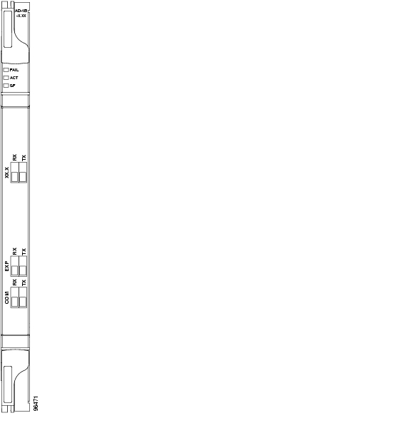
Figure 2-62 shows the AD-1B-xx.x faceplate.
Figure 2-62 AD-1B-xx.x Faceplate
For information on safety labels for the card, see the "Class 1M Laser Product Cards" section.
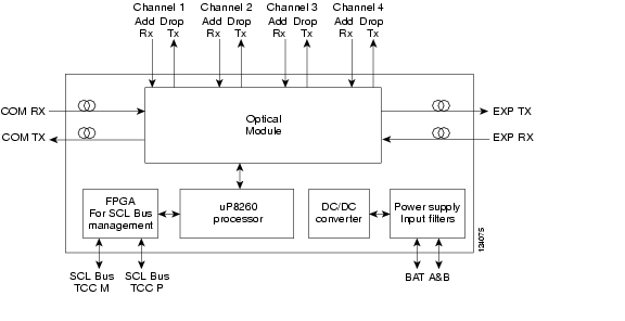
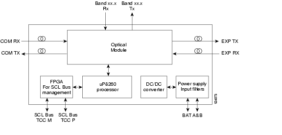
Figure 2-63 shows a block diagram of the AD-1B-xx.x card.
Figure 2-63 AD-1B-xx.x Block Diagram
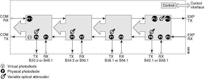
Figure 2-64 shows the AD-1B-xx.x optical module functional block diagram.
Figure 2-64 AD-1B-xx.x Optical Module Functional Block Diagram
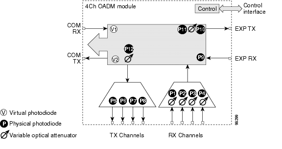
2.8.4.1 Power Monitoring
Physical photodiodes P1 through P4 and virtual photodiodes V1 and V2 monitor the power for the AD-1B-xx.x card. The returned power level values are calibrated to the ports as shown in Table 2-53.
Table 2-53 AD-1B-xx.x Port Calibration
P1
ADD
BAND RX
P2
DROP
BAND TX
P3
IN EXP
EXP RX
P4
OUT EXP
EXP TX
V1
IN COM
COM RX
V2
OUT COM
COM TX
2.8.4.2 AD-1B-xx.x Card-Level Indicators
The AD-1B-xx.x card has three card-level LED indicators, described in Table 2-54.
2.8.4.3 AD-1B-xx.x Port-Level Indicators
You can find the status of the card port using the LCD screen on the ONS 15454 fan-tray assembly. Use the LCD to view the status of any port or card slot; the screen displays the number and severity of alarms for a given port or slot. The AD-1B-xx.x has six LC-PC-II optical ports: two for add/drop channel client input and output, two for express channel input and output, and two for communication.
2.8.5 AD-4B-xx.x Card
The 4-Band OADM (AD-4B-xx.x) card passively adds or drops four bands of four adjacent 100-GHz-spaced channels. Two versions of this card with different part numbers—each version designed for use with one set of bands—are used in the ONS 15454 DWDM system. The card bidirectionally adds and drops in two different sections on the same card to manage signal flow in both directions. This card can be used when there is asymmetric adding and dropping on each side (east or west) of the node; a band can be added or dropped on one side but not on the other.
The AD1B-xx.x can be installed in Slots 1 to 6 and 12 to 17 and has the following features:
•
•
•
•
•
Figure 2-65 shows the AD-4B-xx.x faceplate.
Figure 2-65 AD-4B-xx.x Faceplate
For information on safety labels for the card, see the "Class 1M Laser Product Cards" section.
Figure 2-66 shows a block diagram of the AD-4B-xx.x card.
Figure 2-66 AD-4B-xx.x Block Diagram
Figure 2-67 shows the AD-4B-xx.x optical module functional block diagram.
Figure 2-67 AD-4B-xx.x Optical Module Functional Block Diagram
2.8.5.1 Power Monitoring
Physical photodiodes P1 through P11 and virtual photodiode V1 monitor the power for the AD-4B-xx.x card. The returned power level values are calibrated to the ports as shown in Table 2-55.
Table 2-55 AD-4B-xx.x Port Calibration
P1-P4
ADD
COM TX
P5-P8
DROP
DROP TX
P9
IN EXP
EXP RX
P10
OUT EXP
EXP TX
P11
IN COM
COM RX
V1
OUT COM
COM TX
2.8.5.2 AD-4B-xx.x Card-Level Indicators
The AD-4B-xx.x card has three card-level LED indicators, described in Table 2-56.
2.8.5.3 AD-4B-xx.x Port-Level Indicators
You can find the status of the card port using the LCD screen on the ONS 15454 fan-tray assembly. Use the LCD to view the status of any port or card slot; the screen displays the number and severity of alarms for a given port or slot. The AD-4B-xx.x has 12 LC-PC-II optical ports: eight for add/drop band client input and output, two for express channel input and output, and two for communication.
2.8.6 32WSS Card
The 32-Channel Wavelength Selective Switch (32WSS) card performs channel add/drop processing within the ONS 15454 DWDM node. The 32WSS works in conjunction with the 32DMX to implement ROADM functionality. Equipped with ROADM functionality, the ONS 15454 DWDM can be configured to add or drop individual optical channels using CTC, Cisco MetroPlanner, and CTM.
An ROADM NE utilizes two 32WSS cards (two slots each) and two 32DMX cards (one slot each), for a total of six slots in the chassis. For a diagram of a typical ROADM configuration, see the "3.1.4 ROADM Node" section on page 3-9. The 32WSS card can be installed in Slots 1 and 2, 3 and 4, 5 and 6, 12 and 13, 14 and 15, or 16 and 17.
The 32WSS has six types of ports:
•
•
•
•
•
•
A terminal site can be configured using only a 32WSS card and a 32DMX card plugged into the east or west side of the shelf.
Figure 2-68 shows the 32WSS module front panel and identifies the traffic flow through the ports.
Figure 2-68 32WSS Faceplate and Ports
For information on safety labels for the card, see the "Class 1M Laser Product Cards" section.
Figure 2-69 provides a high-level functional block diagram of the 32WSS card.
Figure 2-69 32WSS Block Diagram
Aggregate optical signals that enter the EXP RX and COM RX port are processed in two ways. The optical processing stages are shown in Figure 2-70, which provides a detailed optical functional diagram of the 32WSS card.
Figure 2-70 32WSS Optical Block Diagram
The EX PORT and COM PORT operate as follows:
•
The incoming optical signal is received at the EXP RX port from the other 32WSS module within the NE. The incoming aggregate optical signal is demultiplexed into 32 individual wavelength components, or channels. Then, each channel is individually processed by the optical switch, which performs add/pass-through processing. Under software control, the switch either selects the optical channel coming in from the demultiplexer (the pass-through channel) or it selects the external ADD channel. If the ADD port channel is selected, the optical signal coming from the demultiplexer is blocked, and the ADD channel is transmitted in its place.
After the optical switch stage, all of the channels are multiplexed together into an aggregate optical signal, which is sent out on the COM TX port. The output is typically connected to an OPT-BST or OPT-BST-E (in the event a booster amplifier is needed) or to an OSC-CSM (if no amplification is needed).
•
The incoming optical signal received at the COM RX port and is applied to the optical splitter within the 32WSS. Channels that are designated to be dropped are diverted optically to the DROP TX port by the splitter. The DROP TX port on the 32WSS is typically connected to the COM RX port of the 32DMX where the drop channels are dropped. Channels that are not dropped pass through the optical splitter and flow out of the EXP TX port of the 32WSS. This optical signal is typically connected to the other 32WSS module within the NE.
2.8.6.1 Power Monitoring
Physical photodiodes P1 through P69 monitor the power for the 32WSS card. The returned power level values are calibrated to the ports as shown in Table 2-57.
Table 2-57 32WSS Port Calibration
P1-P32
ADD (Power ADD)
ADD RX
P33-P641
PASS THROUGH
COM TX
ADD (Power)
COM TX
P65
OUT EXP
EXP TX
P66
IN EXP
EXP RX
P67
OUT COM
COM TX
P68
IN COM
COM RX
P69
DROP
DROP TX
1 P33-P64 monitor either ADD or PASSTHROUGH power, depending on the state of the optical switch
2.8.6.2 32WSS Card-Level Indicators
Table 2-58 describes the three card-level LED indicators on the 32WSS card.
2.8.6.3 32WSS Port-Level Indicators
You can find the status of the 32WSS card's ports using the LCD screen on the ONS 15454 fan-tray assembly. Use the LCD to view the status of any port or card slot; the screen displays the number and severity of alarms for a given port or slot. The 32WSS card has five sets of ports located on the faceplate. COM RX is the line input, COM TX is the line output, EXP RX is the port where a channel can be added or passed through, EXP TX is the port that passes through the channels that are not dropped, and DROP TX is the port for the dropped channels. The xx.x to yy.y TX ports represent the four groups of eight channels ranging from wavelength xx.x to wavelength yy.y according to the channel plan.
2.8.7 32WSS-L Card
The 32-Channel Wavelength Selective Switch L-Band (32WSS-L) card performs channel add/drop processing within the ONS 15454 DWDM node. The 32WSS-L works in conjunction with the 32DMX-L to implement ROADM functionality within the L band (1570 to 1620 nm). The 32WSS-L card is particularly well suited for use in networks that employ DS fiber or SMF-28 single-mode fiber. Equipped with ROADM functionality, the ONS 15454 DWDM can be configured to add or drop individual optical channels using CTC, Cisco MetroPlanner, and CTM.
An ROADM NE utilizes two 32WSS-L cards (two slots each) and two 32DMX-L cards (one slot each), for a total of six slots in the chassis. For a diagram of a typical ROADM configuration, see the "3.1.4 ROADM Node" section on page 3-9. The 32WSS-L card can be installed in Slots 1 and 2, 3 and 4, 5 and 6, 12 and 13, 14 and 15, or 16 and 17.
The 32WSS-L has six types of ports:
•
•
•
•
•
•
A terminal site can be configured using only a 32WSS-L card and a 32DMX-L card plugged into the east or west side of the shelf.
Figure 2-71 shows the 32WSS-L module front panel and identifies the traffic flow through the ports.
Figure 2-71 32WSS-L Faceplate and Ports
For information on safety labels for the card, see the "Class 1M Laser Product Cards" section.
Figure 2-72 provides a high-level functional block diagram of the 32WSS-L card.
Figure 2-72 32WSS-L Block Diagram
Aggregate optical signals that enter the EXP RX and COM RX ports are processed in two ways. The optical processing stages are shown in Figure 2-73, which provides a detailed optical functional diagram of the 32WSS-L card.
Figure 2-73 32WSS-L Optical Block Diagram
The EX PORT and COM PORT operate as follows:
•
The incoming optical signal is received at the EXP RX port from the other 32WSS-L module within the NE. The incoming aggregate optical signal is demultiplexed into 32 individual wavelength components, or channels. Then each channel is individually processed by the optical switch, which does add/pass-through processing. Under software control, the switch either selects the optical channel coming in from the demultiplexer (the pass-through channel) or it selects the external ADD channel. If the ADD port channel is selected, the optical signal coming from the demultiplexer is blocked, and the ADD channel is transmitted in its place.
After the optical switch stage, all of the channels are multiplexed together into an aggregate optical signal, which is sent out on the COM TX port. The output is typically connected to an OPT-AMP-L (in the event a booster amplifier is needed) or to an OSC-CSM (if no amplification is needed).
•
The incoming optical signal received at the COM RX port is applied to the optical splitter within the 32WSS-L. Channels that are designated to be dropped are diverted optically to the DROP TX port by the splitter. The DROP TX port on the 32WSS-L is typically connected to the COM RX port of the 32DMX-L where the drop channels are dropped. Channels that are not dropped pass through the optical splitter and flow out of the EXP TX port of the 32WSS-L. This optical signal is typically connected to the other 32WSS-L module within the NE.
2.8.7.1 Power Monitoring
Physical photodiodes P1 through P69 monitor the power for the 32WSS-L card. The returned power level values are calibrated to the ports as shown in Table 2-59.
Table 2-59 32WSS-L Port Calibration
P1-P32
ADD (Power ADD)
ADD RX
P33-P641
PASS THROUGH
COM TX
ADD (Power)
COM TX
P65
OUT EXP
EXP TX
P66
IN EXP
EXP RX
P67
OUT COM
COM TX
P68
IN COM
COM RX
P69
DROP
DROP TX
1 P33-P64 monitor either ADD or PASSTHROUGH power, depending on the state of the optical switch
2.8.7.2 Channel Plan
The 32WSS-L card uses 32 channels on the ITU 100-GHz grid in a banded configuration (see Table 2-60).
2.8.7.3 32WSS-L Card-Level Indicators
Table 2-58 describes the three card-level LED indicators on the 32WSS-L card.
2.8.7.4 32WSS-L Port-Level Indicators
You can find the status of the 32WSS-L card's ports using the LCD screen on the ONS 15454 fan-tray assembly. Use the LCD to view the status of any port or card slot; the screen displays the number and severity of alarms for a given port or slot. The 32WSS-L card has five sets of ports located on the faceplate. COM RX is the line input, COM TX is the line output, EXP RX is the port where a channel can be added or passed through, EXP TX is the port that passes through the channels that are not dropped, and DROP TX is the port for the dropped channels. The xx.x to yy.y TX ports represent the four groups of eight channels ranging from wavelength xx.x to wavelength yy.y according to the channel plan.
2.8.8 MMU Card
The MMU card supports multiring and mesh upgrades for ROADM nodes in both the C band and the L band. Mesh/multiring upgrade is the capability to optically bypass a given wavelength from one section of the network or ring to another one without requiring 3R regeneration. In each node, you need to install two MMUs, one on the east side and one on the west side. You can install the MMU card in Slots 1 through 6 and 12 through 17.
The MMU has six ports:
•
•
•
•
•
•
Figure 2-71 shows the MMU module front panel.
Figure 2-74 MMU Faceplate and Ports
For information on safety labels for the card, see the "Class 1M Laser Product Cards" section.
Figure 2-72 provides a high-level functional block diagram of the MMU card.
Figure 2-75 MMU Block Diagram
2.8.8.1 Power Monitoring
Physical photodiodes P1 through P3 monitor the power for the MMU card. The returned power level values are calibrated to the ports as shown in Table 2-62. VP1 to VP3 are virtual photodiodes that have been created by adding (by software computation) the relevant path insertion losses of the optical splitters (stored in the module) to the real photodiode (P1 to P3) measurement.
2.8.8.2 MMU Card-Level Indicators
Table 2-63 describes the three card-level LED indicators on the MMU card.
2.8.8.3 MMU Port-Level Indicators
You can find the status of the MMU card's ports using the LCD screen on the ONS 15454 fan-tray assembly. Use the LCD to view the status of any port or card slot; the screen displays the number and severity of alarms for a given port or slot. The MMU card has six ports located on the faceplate. COM RX is the line input, COM TX is the line output, EXP RX and EXP-A RX are the ports where a channel can be added or passed through, and EXP TX and EXP-A TX are the ports that pass through the channels that are not dropped.
2.9 Transponder and Muxponder Cards
This section describes the transponder (TXP) and muxponder (MXP) cards. Detailed specifications for the cards are found in Appendix A, "Hardware Specifications".
TXP and MXP cards detect SF, LOS, and LOF conditions on the optical facility. Refer to the Cisco ONS 15454 DWDM Troubleshooting Guide for a description of these conditions. The cards also count section and line bit interleaved parity (BIP) errors from B1 and B2 byte registers in the section and line overhead.
2.9.1 TXP_MR_10G Card
The (TXP_MR_10G processes one 10-Gbps signal (client side) into one 10-Gbps, 100-GHz DWDM signal (trunk side). It provides one 10-Gbps port per card that can be provisioned for an STM-64/OC-192 short reach (1310-nm) signal, compliant with ITU-T G.707, G.709, ITU-T G.691, and Telcordia GR-253-CORE, or a 10GBASE-LR signal compliant with IEEE 802.3.
The TXP_MR_10G card is tunable over two neighboring wavelengths in the 1550-nm, ITU 100-GHz range. It is available in 16 different versions, each of which covers two wavelengths, for a total coverage of 32 different wavelengths in the 1550-nm range.
Note
The trunk port operates at 9.95328 Gbps (or 10.70923 Gbps with ITU-T G.709 Digital Wrapper/FEC) and at 10.3125 Gbps (or 11.095 Gbps with ITU-T G.709 Digital Wrapper/FEC) over unamplified distances up to 80 km (50 miles) with different types of fiber such as C-SMF or dispersion compensated fiber limited by loss and/or dispersion.
Caution
Caution
You can install TXP_MR_10G cards in Slots 1 to 6 and 12 to 17 and provision this card in a linear configuration. TXP_MR_10G cards cannot be provisioned as a BLSR/MS-SPRing, a Path Protection/SNCP, or a regenerator. They can only be used in the middle of BLSR/MS-SPRing and 1+1 spans when the card is configured for transparent termination mode.
The TXP_MR_10G port features a 1550-nm laser for the trunk port and a 1310-nm laser for the for the client port and contains two transmit and receive connector pairs (labeled) on the card faceplate.
Figure 2-76 shows the TXP_MR_10G faceplate and block diagram.
Figure 2-76 TXP_MR_10G Faceplate and Block Diagram
For information on safety labels for the card, see the "Class 1M Laser Product Cards" section.
2.9.1.1 Y-Cable Protection
Two TXP_MR_10G cards can be joined in a Y-cable protection group. In Y-cable protection, the client ports of the two cards are joined by Y-cables. A single incoming receive (Rx) client signal is injected into the Rx Y-cable port and is split between the two TXP_MR_10G cards (connected to the Rx client ports) in the protection group. The transmit (Tx) client signals from the two protection group TXP_MR_10G cards are connected to the correspondent ports of the Tx Y-cable. Only the Tx client port of the active TXP_MR_10G card is turned on and transmits the signal toward the receiving client equipment. See the "Transponder and Muxponder Protection" section for more information.
Note
2.9.1.2 Automatic Laser Shutdown
The ALS procedure is supported on both client and trunk interfaces. On the client interface, ALS is compliant with ITU-T G.664 (6/99). On the data application and trunk interface, the switch on and off pulse duration is greater than 60 seconds and is user-configurable. For details on ALS provisioning for the card, see the Cisco ONS 15454 DWDM Procedure Guide.
2.9.1.3 TXP_MR_10G Card-Level Indicators
Table 2-64 lists the three card-level LEDs on the TXP_MR_10G card.
2.9.1.4 TXP_MR_10G Port-Level Indicators
Table 2-65 lists the four port-level LEDs in the TXP_MR_10G card.
2.9.2 TXP_MR_10E Card
The TXP_MR_10E card is a multirate transponder for the ONS 15454 platform. The card is fully backward compatible with the TXP_MR_10G card. It processes one 10-Gbps signal (client side) into one 10-Gbps, 100-GHz DWDM signal (trunk side) that is tunable over four wavelength channels (spaced at 100 GHz on the ITU grid) in the C band and tunable over eight wavelength channels (spaced at 50 GHz on the ITU grid) in the L band. There are eight versions of the C-band card, with each version covering four wavelengths, for a total coverage of 32 wavelengths. There are five versions of the L-band card, with each version covering eight wavelengths, for a total coverage of 40 wavelengths.
You can install TXP_MR_10E cards in Slots 1 to 6 and 12 to 17 and provision the cards in a linear configuration, BLSR/MS-SPRing, Path Protection/SNCP, or a regenerator. The card can be used in the middle of BLSR/MS-SPRing or 1+1 spans when the card is configured for transparent termination mode.
The TXP_MR_10E card features a 1550-nm tunable laser (C band) or a 1580-nm tunable laser (L band) for the trunk port and a separately orderable ONS-XC-10G-S1 1310-nm laser XFP module or ONS-XC-10G-L2 1550-nm laser XFP module for the client port.
Note
On its faceplate, the TXP_MR_10E card contains two transmit and receive connector pairs, one for the trunk port and one for the client port. Each connector pair is labeled.
2.9.2.1 Key Features
The key features of the TXP_MR_10E card are:
•
–
–
–
•
2.9.2.2 Faceplate and Block Diagram
Figure 2-77 shows the TXP_MR_10E faceplate and block diagram.
Figure 2-77 TXP_MR_10E Faceplate and Block Diagram
For information on safety labels for the card, see the "Class 1M Laser Product Cards" section.
Caution
2.9.2.3 Client Interface
The client interface is implemented with a separately orderable XFP module. The module is a tri-rate transceiver, providing a single port that can be configured in the field to support an OC-192 SR-1 (Telcordia GR-253-CORE) or STM-64 I-64.1 (ITU-T G.691) optical interface, as well as 10GE LAN PHY (10GBASE-LR), 10GE WAN PHY (10GBASE-LW), or 10G FC signals.
The client side XFP pluggable module supports LC connectors and is equipped with a 1310-nm laser.
2.9.2.4 DWDM Trunk Interface
On the trunk side, the TXP_MR_10E card provides a 10-Gbps STM-64/OC-192 interface. There are four tunable channels available in the 1550-nm band or eight tunable channels available in the 1580-nm band on the 50-GHz ITU grid for the DWDM interface. The TXP_MR_10E card provides 3R transponder functionality for this 10-Gbps trunk interface. Therefore, the card is suited for use in long-range amplified systems. The DWDM interface is complaint with ITU-T G.707, ITU-T G.709, and Telcordia GR-253-CORE standards.
The DWDM trunk port operates at a rate that is dependent on the input signal and the presence or absence of the ITU-T G.709 Digital Wrapper/FEC. The possible trunk rates are:
•
•
•
•
The maximum system reach in filterless applications without the use of optical amplification or regenerators is nominally rated at 23 dB over C-SMF fiber. This rating is not a product specification, but is given for informational purposes. It is subject to change.
2.9.2.5 Y-Cable Protection
The TXP_MR_10E card supports Y-cable protection, which provides transponder equipment protection without client terminal equipment interface protection. A single client interface can be split between two transponder cards using a Y-protection device.
With Y-cable protection, two TXP_MR_10E transponder cards can be joined in a Y-cable protection group. In Y-cable protection, the client ports of the two cards are joined by Y cables. An incoming client signal is injected into the Rx Y-cable port and is split between the two TXP_MR_10E cards (connected to Rx client ports) in the protection group. The Tx client signals from the two protection group TXP_MR_10E cards are connected to the correspondent ports of the Tx Y cable. Only the Tx client port of the active TXP_MR_10E card is turned on and transmits the signal towards the receiving client equipment. See the "Y-Cable Protection" section for more details.
Note
2.9.2.6 Enhanced FEC (E-FEC) Feature
A key feature of the TXP_MR_10E is the availability to configure the forward error correction in three modes: NO FEC, FEC, and E-FEC. The output bit rate is always 10.7092 Gbps as defined in ITU-T G.709, but the error coding performance can be provisioned as follows:
•
•
•
2.9.2.7 FEC and E-FEC Modes
As client side traffic passes through the TXP_MR_10E card, it can be digitally wrapped using FEC mode, E-FEC mode, or no error correction at all. The FEC mode setting provides a lower level of error detection and correction than the E-FEC mode setting of the card. As a result, using E-FEC mode allows higher sensitivity (lower optical signal-to-noise ratio [OSNR]) with a lower bit error rate than FEC mode. E-FEC enables longer distance trunk-side transmission than with FEC.
The E-FEC feature is one of three basic modes of FEC operation. FEC can be turned off, FEC can be turned on, or E-FEC can be turned on to provide greater range and lower BER. The default mode is FEC on and E-FEC off. E-FEC is provisioned using CTC.
Caution
2.9.2.8 Client-to-Trunk Mapping
The TXP_MR_10E card can perform ODU2-to-OCh mapping, which allows operators to provision data payloads in a standard way across 10-Gbps optical links.
Digital wrappers that define client side interfaces are called Optical Data Channel Unit 2 (ODU2) entities in ITU-T G.709. Digital wrappers that define trunk side interfaces are called Optical Channels (OCh) in ITU-T G.709. ODU2 digital wrappers can include Generalized Multiprotocol Label Switching (G-MPLS) signaling extensions to ITU-T G.709 (such as Least Significant Part [LSP] and Generalized Payload Identifier [G-PID] values) to define client interfaces and payload protocols.
2.9.2.9 Automatic Laser Shutdown
The ALS procedure is supported on both client and trunk interfaces. On the client interface, ALS is compliant with ITU-T G.664 (6/99). On the data application and trunk interface, the switch on and off pulse duration is greater than 60 seconds. The on and off pulse duration is user-configurable. For details on ALS provisioning for the card, see the Cisco ONS 15454 DWDM Procedure Guide.
2.9.2.10 TXP_MR_10E Card-Level Indicators
Table 2-66 lists the three card-level LEDs on the TXP_MR_10E card.
2.9.2.11 TXP_MR_10E Port-Level Indicators
Table 2-67 lists the two port-level LEDs in the TXP_MR_10E card.
2.9.3 TXP_MR_10E_C and TXP_MR_10E_L Cards
The TXP_MR_10E_C and TXP_MR_10E_L cards are multirate transponders for the ONS 15454 platform. The cards are fully backward compatible with the TXP_MR_10G and TXP_MR_10E cards. They processes one 10-Gbps signal (client side) into one 10-Gbps, 100-GHz DWDM signal (trunk side). The TXP_MR_10E_C is tunable over the entire set of C-band wavelength channels (82 channels spaced at 50 GHz on the ITU grid). The TXP_MR_10E_L is tunable over the entire set of L-band wavelength channels (80 channels spaced at 50 GHz on the ITU grid) and is particularly well suited for use in networks that employ DS fiber or SMF-28 single-mode fiber.
The advantage of these cards over previous versions (TXP_MR_10G and TXP_MR_10E) is that there is only one version of each card (one C-band version and one L-band version) instead of several versions needed to cover each band.
You can install TXP_MR_10E_C and TXP_MR_10E_L cards in Slots 1 to 6 and 12 to 17 and provision the cards in a linear configuration, BLSR/MS-SPRing, Path Protection/SNCP, or a regenerator. The cards can be used in the middle of BLSR/MS-SPRing or 1+1 spans when the cards are configured for transparent termination mode.
The TXP_MR_10E card features a universal transponder 2 (UT2) 1550-nm tunable laser (C band) or a UT2 1580-nm tunable laser (L band) for the trunk port and a separately orderable ONS-XC-10G-S1 1310-nm laser XFP module or ONS-XC-10G-L2 1550-nm laser XFP module for the client port.
Note
On its faceplate, the TXP_MR_10E_C and TXP_MR_10E_L cards contain two transmit and receive connector pairs, one for the trunk port and one for the client port. Each connector pair is labeled.
2.9.3.1 Key Features
The key features of the TXP_MR_10E_C and TXP_MR_10E_L cards are:
•
–
–
–
•
•
2.9.3.2 Faceplates and Block Diagram
Figure 2-78 shows the TXP_MR_10E_C and TXP_MR_10E_L faceplates and block diagram.
Figure 2-78 TXP_MR_10E_C and TXP_MR_10E_L Faceplates and Block Diagram
For information on safety labels for the cards, see the "Class 1M Laser Product Cards" section.
Caution
2.9.3.3 Client Interface
The client interface is implemented with a separately orderable XFP module. The module is a tri-rate transceiver, providing a single port that can be configured in the field to support an OC-192 SR-1 (Telcordia GR-253-CORE) or STM-64 I-64.1 (ITU-T G.691) optical interface, as well as 10GE LAN PHY (10GBASE-LR), 10GE WAN PHY (10GBASE-LW), or 10G-FC signals.
The client side XFP pluggable module supports LC connectors and is equipped with a 1310-nm laser.
2.9.3.4 DWDM Trunk Interface
On the trunk side, the TXP_MR_10E_C and TXP_MR_10E_L cards provide a 10-Gbps STM-64/OC-192 interface. There are 80 tunable channels available in the 1550-nm C band or 82 tunable channels available in the 1580-nm L band on the 50-GHz ITU grid for the DWDM interface. The TXP_MR_10E_C and TXP_MR_10E_C cards provide 3R transponder functionality for this 10-Gbps trunk interface. Therefore, the card is suited for use in long-range amplified systems. The DWDM interface is compliant with ITU-T G.707, ITU-T G.709, and Telcordia GR-253-CORE standards.
The DWDM trunk port operates at a rate that is dependent on the input signal and the presence or absence of the ITU-T G.709 Digital Wrapper/FEC. The possible trunk rates are:
•
•
•
•
The maximum system reach in filterless applications without the use of optical amplification or regenerators is nominally rated at 23 dB over C-SMF fiber. This rating is not a product specification, but is given for informational purposes. It is subject to change.
2.9.3.5 Y-Cable Protection
The TXP_MR_10E card supports Y-cable protection, which provides transponder equipment protection without client terminal equipment interface protection. A single client interface can be split between two transponder cards using a Y-protection device.
With Y-cable protection, two TXP_MR_10E_C or two TXP_MR_10E_L transponder cards can be joined in a Y-cable protection group. In Y-cable protection, the client ports of the two cards are joined by Y cables. An incoming client signal is injected into the Rx Y-cable port and is split between the two cards (connected to Rx client ports) in the protection group. The Tx client signals from the two protection group cards are connected to the correspondent ports of the Tx Y cable. Only the Tx client port of the active card is turned on and transmits the signal towards the receiving client equipment. See the "Y-Cable Protection" section for more details.
Note
2.9.3.6 Enhanced FEC (E-FEC) Feature
A key feature of the TXP_MR_10E_C and TXP_MR_10E_L cards is the availability to configure the forward error correction in three modes: NO FEC, FEC, and E-FEC. The output bit rate is always 10.7092 Gbps as defined in ITU-T G.709, but the error coding performance can be provisioned as follows:
•
•
•
2.9.3.7 FEC and E-FEC Modes
As client side traffic passes through the TXP_MR_10E_C and TXP_MR_10E_L cards, it can be digitally wrapped using FEC mode, E-FEC mode, or no error correction at all. The FEC mode setting provides a lower level of error detection and correction than the E-FEC mode setting of the card. As a result, using E-FEC mode allows higher sensitivity (lower OSNR) with a lower bit error rate than FEC mode. E-FEC enables longer distance trunk-side transmission than with FEC.
The E-FEC feature is one of three basic modes of FEC operation. FEC can be turned off, FEC can be turned on, or E-FEC can be turned on to provide greater range and lower BER. The default mode is FEC on and E-FEC off. E-FEC is provisioned using CTC.
Caution
2.9.3.8 Client-to-Trunk Mapping
The TXP_MR_10E_C and TXP_MR_10E_L cards can perform ODU2-to-OCh mapping, which allows operators to provision data payloads in a standard way across 10-Gbps optical links.
Digital wrappers that define client side interfaces are called ODU2 entities in ITU-T G.709. Digital wrappers that define trunk side interfaces are called OCh in ITU-T G.709. ODU2 digital wrappers can include G-MPLS signaling extensions to ITU-T G.709 (such as LSP and G-PID values) to define client interfaces and payload protocols.
2.9.3.9 Automatic Laser Shutdown
The ALS procedure is supported on both client and trunk interfaces. On the client interface, ALS is compliant with ITU-T G.664 (6/99). On the data application and trunk interface, the switch on and off pulse duration is greater than 60 seconds. The on and off pulse duration is user-configurable. For details regarding ALS provisioning for the TXP_MR_10E_C and TXP_MR_10E_L cards, see the Cisco ONS 15454 DWDM Procedure Guide.
2.9.3.10 TXP_MR_10E_C and TXP_MR_10E_L Card-Level Indicators
Table 2-68 lists the three card-level LEDs on the TXP_MR_10E_C and TXP_MR_10E_L cards.
2.9.3.11 TXP_MR_10E_C and TXP_MR_10E_L Port-Level Indicators
Table 2-69 lists the two port-level LEDs in the TXP_MR_10E_C and TXP_MR_10E_L cards.
2.9.4 TXP_MR_2.5G and TXPP_MR_2.5G Cards
The TXP_MR_2.5G card processes one 8-Mbps to 2.488-Gbps signal (client side) into one 8-Mbps to 2.5-Gbps, 100-GHz DWDM signal (trunk side). It provides one long-reach STM-16/OC-48 port per card, compliant with ITU-T G.707, ITU-T G.709, ITU-T G.957, and Telcordia GR-253-CORE.
The TXPP_MR_2.5G card processes one 8-Mbps to 2.488-Gbps signal (client side) into two 8-Mbps to 2.5-Gbps, 100-GHz DWDM signals (trunk side). It provides two long-reach STM-16/OC-48 ports per card, compliant with ITU-T G.707, ITU-T G.957, and Telcordia GR-253-CORE.
The TXP_MR_2.5G and TXPP_MR_2.5G cards are tunable over four wavelengths in the 1550-nm, ITU 100-GHz range. They are available in eight versions, each of which covers four wavelengths, for a total coverage of 32 different wavelengths in the 1550-nm range.
Note
The trunk/line port operates at up to 2.488 Gbps (or up to 2.66 Gbps with ITU-T G.709 Digital Wrapper/FEC) over unamplified distances up to 360 km (223.7 miles) with different types of fiber such as C-SMF or higher if dispersion compensation is used.
Caution
The TXP_MR_2.5G and TXPP_MR_2.5G cards support 2R and 3R modes of operation where the client signal is mapped into a ITU-T G.709 frame. The mapping function is simply done by placing a digital wrapper around the client signal. Only OC-48/STM-16 client signals are fully ITU-T G.709 compliant, and the output bit rate depends on the input client signal. Table 2-70 shows the possible combinations of client interfaces, input bit rates, 2R and 3R modes, and ITU-T G.709 monitoring.
Table 2-70 2R and 3R Mode and ITU-T G.709 Compliance by Client Interface
OC-48/STM-16
2.488 Gbps
3R
On or Off
DV-6000
2.38 Gbps
2R
—
2 Gigabit Fibre Channel (2G-FC)/fiber connectivity (FICON)
2.125 Gbps
3R1
On or Off
High-Definition Television (HDTV)
1.48 Gbps
2R
—
Gigabit Ethernet (GE)
1.25 Gbps
3R
On or Off
1 Gigabit Fibre Channel (1G-FC)/FICON
1.06 Gbps
3R
On or Off
OC-12/STM-4
622 Mbps
3R
On or Off
OC-3/STM-1
155 Mbps
3R
On or Off
Enterprise System Connection (ESCON)
200 Mbps
2R
—
SDI/D1 video
270 Mbps
2R
—
ISC-1 Compact
1.06 Gbps
3R
Off
ISC-3
1.06 or 2.125 Gbps
2R
—
ETR_CLO
16 Mbps
2R
—
1 No monitoring
The output bit rate is calculated for the trunk bit rate by using the 255/238 ratio as specified in ITU-T G.709 for OTU1. Table 2-71 lists the calculated trunk bit rates for the client interfaces with ITU-T G.709 enabled.
For 2R operation mode, the TXP_MR_2.5G and TXPP_MR_2.5G cards have the ability to pass data through transparently from client side interfaces to a trunk side interface, which resides on an ITU grid. The data might vary at any bit rate from 200-Mbps up to 2.38-Gbps, including ESCON and video signals. In this pass-through mode, no performance monitoring (PM) or digital wrapping of the incoming signal is provided, except for the usual PM outputs from the SFPs. Similarly, this card has the ability to pass data through transparently from the trunk side interfaces to the client side interfaces with bit rates varying from 200-Mbps up to 2.38-Gbps. Again, no PM or digital wrapping of received signals is available in this pass-through mode.
For 3R operation mode, the TXP_MR_2.5G and TXPP_MR_2.5G cards apply a digital wrapper to the incoming client interface signals (OC-N/STM-N, 1G-FC, 2G-FC, GE). PM is available on all of these signals except for 2G-FC, and varies depending upon the type of signal. For client inputs other than OC-48/STM-16, a digital wrapper might be applied but the resulting signal is not ITU-T G.709 compliant. The card applies a digital wrapper that is scaled to the frequency of the input signal.
The TXP_MR_2.5G and TXPP_MR_2.5G cards have the ability to take digitally wrapped signals in from the trunk interface, remove the digital wrapper, and send the unwrapped data through to the client interface. PM of the ITU-T G.709 OH and SONET/SDH OH is implemented.
2.9.4.1 Faceplate
Figure 2-79 shows the TXP_MR_2.5G and TXPP_MR_2.5G faceplates.
Figure 2-79 TXP_MR_2.5G and TXPP_MR_2.5G Faceplates
For information on safety labels for the cards, see the "Class 1M Laser Product Cards" section.
2.9.4.2 Block Diagram
Figure 2-80 shows a block diagram of the TXP_MR_2.5G and TXPP_MR_2.5G cards.
Figure 2-80 TXP_MR_2.5G and TXPP_MR_2.5G Block Diagram
Caution
You can install TXP_MR_2.5G and TXPP_MR_2.5G cards in Slots 1 to 6 and 12 to 17. You can provision this card in a linear configuration. TXP_MR_10G and TXPP_MR_2.5G cards cannot be provisioned as a BLSR/MS-SPRing, a Path Protection/SNCP, or a regenerator. They can be used in the middle of BLSR/MS-SPRing or 1+1 spans only when the card is configured for transparent termination mode.
The TXP_MR_2.5G card features a 1550-nm laser for the trunk/line port and a 1310-nm laser for the client port. It contains two transmit and receive connector pairs (labeled) on the card faceplate. The card uses dual LC connectors for optical cable termination.
The TXPP_MR_2.5G card features a 1550-nm laser for the trunk/line port and a 1310-nm or 850-nm laser (depending on the SFP) for the client port and contains three transmit and receive connector pairs (labeled) on the card faceplate. The card uses dual LC connectors for optical cable termination.
2.9.4.3 Y-Cable Protection
For the TXP_MR_2.5G card, protection is done using Y-cable protection. In Y-cable protection, the client ports of two TXP_MR_2.5G cards can be joined by Y cables in a Y-cable protection group. A single incoming Rx client signal is injected into the Rx Y-cable port and is split between the two TXP_MR_2.5G cards (connected to the Rx client ports) in the protection group. The Tx client signals from the two protection group TXP_MR_2.5G cards are connected to the correspondent ports of the Tx Y-cable. Only the Tx client port of the active TXP_MR_2.5G card is turned on and transmits the signal towards the receiving client equipment. See the "Transponder and Muxponder Protection" section for more information.
Note
2.9.4.4 Splitter Protection
For the TXPP_MR_2.5G card, protection is done using splitter protection. In splitter protection, the single client signal is injected into the client Rx port. It is then split into two separate signals on the two trunk Tx ports. The two signals are transmitted over diverse paths. The far-end TXPP_MR_2.5G card chooses one of the two trunk Rx port signals and injects it into the Tx client port. The TXPP_MR_2.5G card switches the selected trunk Rx port signal in case of failure. See the "Transponder and Muxponder Protection" section for more details.
2.9.4.5 Automatic Laser Shutdown
The ALS procedure is supported on both client and trunk interfaces. On the client interface, ALS is compliant with ITU-T G.664 (6/99). On the data application and trunk interface, the switch on and off pulse duration is greater than 60 seconds. The on and off pulse duration is user-configurable. For details regarding ALS provisioning for the TXP_MR_2.5G and TXPP_MR_2.5G cards, see the Cisco ONS 15454 DWDM Procedure Guide.
2.9.4.6 TXP_MR_2.5G and TXPP_MR_2.5G Card-Level Indicators
Table 2-72 lists the three card-level LEDs on the TXP_MR_2.5G and TXPP_MR_2.5G cards.
2.9.4.7 TXP_MR_2.5G and TXPP_MR_2.5G Port-Level Indicators
Table 2-73 lists the four port-level LEDs on the TXP_MR_2.5G and TXPP_MR_2.5G cards.
2.9.5 MXP_2.5G_10G Card
The MXP_2.5G_10G card multiplexes/demultiplexes four 2.5-Gbps signals (client side) into one 10-Gbps, 100-GHz DWDM signal (trunk side). It provides one extended long-range STM-64/OC-192 port per card on the trunk side (compliant with ITU-T G.707, ITU-T G.709, ITU-T G.957, and Telcordia GR-253-CORE) and four intermediate- or short-range OC-48/STM-16 ports per card on the client side. The port operates at 9.95328 Gbps over unamplified distances up to 80 km (50 miles) with different types of fiber such as C-SMF or dispersion compensated fiber limited by loss and/or dispersion.
Client ports on the MXP_2.5G_10G card are also interoperable with SONET OC-1 (STS-1) fiber optic signals defined in Telcordia GR-253-CORE. An OC-1 signal is the equivalent of one DS-3 channel transmitted across optical fiber. OC-1 is primarily used for trunk interfaces to phone switches in the United States. There is no SDH equivalent for SONET OC-1.
The MXP_2.5G_10G card is tunable over two neighboring wavelengths in the 1550-nm, ITU 100-GHz range. It is available in 16 different versions, each of which covers two wavelengths, for a total coverage of 32 different wavelengths in the 1550-nm range.
Note
The port can also operate at 10.70923 Gbps in ITU-T G.709 Digital Wrapper/FEC mode.
Caution
Caution
You can install MXP_2.5G_10G cards in Slots 1 to 6 and 12 to 17.
Caution
You can provision this card in a linear configuration. MXP_2.5G_10G cards cannot be provisioned as a BLSR/MS-SPRing, a Path Protection/SNCP, or a regenerator. They can be used in the middle of BLSR/MS-SPRing or 1+1 spans only when the card is configured for transparent termination mode.
The MXP_2.5G_10G port features a 1550-nm laser on the trunk port and four 1310-nm lasers on the client ports and contains five transmit and receive connector pairs (labeled) on the card faceplate. The card uses a dual LC connector on the trunk side and SFP connectors on the client side for optical cable termination.
Figure 2-81 shows the MXP_2.5G_10G faceplate.
Figure 2-81 MXP_2.5G_10G Faceplate
For information on safety labels for the card, see the "Class 1 Laser Product Cards" section.
Figure 2-82 shows a block diagram of the MXP_2.5G_10G card.
Figure 2-82 MXP_2.5G_10G Card Block Diagram
2.9.5.1 Y-Cable Protection
For the MXP_2.5G_10G card, protection is done using Y-cable protection. In Y-cable protection, the client ports of two MXP_2.5G_10G cards can be joined by Y cables in a Y-cable protection group. A single Rx client signal is injected into the Rx Y-cable and is split between the two MXP_2.5G_10G cards in the protection group. The Tx client signals from the two protection group MXP_2.5G_10G cards are connected via the TX Y cable with only the active card signal passing through as the single TX client signal. See the "Y-Cable Protection" section for more details.
Note
2.9.5.2 Timing Synchronization
The MXP_2.5G_10G card is synchronized to the TCC2/TCC2P clock during normal conditions and transmits the ITU-T G.709 frame using this clock. The TCC2/TCC2P card can operate from an external BITS clock, an internal Stratum 3 clock, or from clock recovered from one of the four valid client clocks. If clocks from both TCC2/TCC2P cards are not available, the MXP_2.5G_10G card switches automatically (with errors, not hitless) to an internal 19.44 MHz clock that does not meet SONET clock requirements. This will result in a clock alarm.
2.9.5.3 Automatic Laser Shutdown
The ALS procedure is supported on both client and trunk interfaces. On the client interface, ALS is compliant with ITU-T G.664 (6/99). On the data application and trunk interface, the switch on and off pulse duration is greater than 60 seconds. The on and off pulse duration is user-configurable. For details regarding ALS provisioning for the MXP_2.5G_10G card, refer to the Cisco ONS 15454 DWDM Procedure Guide.
2.9.5.4 MXP_2.5G_10G Card-Level Indicators
Table 2-74 describes the three card-level LEDs on the MXP_2.5G_10G card.
2.9.5.5 MXP_2.5G_10G Port-Level Indicators
Table 2-75 describes the four port-level LEDs on the MXP_2.5G_10G card.
2.9.6 MXP_2.5G_10E Card
The MXP_2.5G_10E card is a DWDM muxponder for the ONS 15454 platform that supports full optical transparency on the client side. The card multiplexes four 2.5 Gbps client signals (4 x OC48/STM-16 SFP) into a single 10-Gbps DWDM optical signal on the trunk side. The MXP_2.5G_10E provides wavelength transmission service for the four incoming 2.5 Gbps client interfaces. The MXP_2.5G_10E muxponder passes all SONET/SDH overhead bytes transparently.
The digital wrapper function (ITU-T G.709 compliant) formats the DWDM wavelength so that it can be used to set up GCCs for data communications, enable FEC, or facilitate performance monitoring.
The MXP_2.5G_10E works with OTN devices defined in ITU-T G.709. The card supports ODU1 to OTU2 multiplexing, an industry standard method for asynchronously mapping a SONET/SDH payload into a digitally wrapped envelope. See the "Multiplexing Function" section.
The MXP_2.5G_10E card is not compatible with the MXP_2.5G_10G card, which does not support full optical transparency. The faceplate designation of the card is "4x2.5G 10E MXP."
You can install MXP_2.5G_10E cards in Slots 1 to 6 and 12 to 17. You can provision this card in a linear configuration, as a BLSR/MS-SPRing, a Path Protection/SNCP, or a regenerator. The card can be used in the middle of BLSR/MS-SPRing or 1+1 spans when the card is configured for transparent termination mode.
The MXP_2.5G_10E features a 1550-nm laser on the trunk port and four 1310-nm lasers on the client ports and contains five transmit and receive connector pairs (labeled) on the card faceplate. The card uses a dual LC connector on the trunk side and uses SFP modules on the client side for optical cable termination. The SFP pluggable modules are short reach (SR) or intermediate reach (IR) and support an LC fiber connector.
2.9.6.1 Key Features
The MXP_2.5G_10E card has the following high level features:
•
•
•
•
•
•
•
•
2.9.6.2 Faceplate
Figure 2-83 shows the MXP_2.5G_10E faceplate.
Figure 2-83 MXP_2.5G_10E Faceplate
For information on safety labels for the card, see the "Class 1 Laser Product Cards" section.
Figure 2-84 shows a block diagram of the MXP_2.5G_10E card.
Figure 2-84 MXP_2.5G_10E Block Diagram
2.9.6.3 Client Interfaces
The MXP_2.5G_10E provides four intermediate- or short-range OC-48/STM-16 ports per card on the client side. Both SR-1 or IR-1 optics can be supported and the ports use SFP connectors. The client interfaces use four wavelengths in the 1310-nm, ITU 100-MHz-spaced, channel grid.
2.9.6.4 DWDM Interface
The MXP_MP_10E serves as an OTN multiplexer, transparently mapping four OC-48 channels asynchronously to ODU1 into one 10-Gbps trunk. The DWDM trunk is tunable for transmission over four wavelengths in the 1550-nm, ITU 100-GHz spaced channel grid.
Caution
2.9.6.5 Multiplexing Function
The muxponder is an integral part of the optically transparent ROADM network in which data payload channels and wavelengths are processed exclusively at the optical level without electrical to optical (E-O) conversion. The key function of MXP_MP_10E is to multiplex 4 OC-48/STM16 signals onto one ITU-T G.709 OTU2 optical signal (DWDM transmission). The multiplexing mechanism allows the signal to be terminated at a far-end node by another MXP_2.5G_10E card.
Optical transparency on the muxponder is configured using OTUx and ODUx OH bytes. The ITU-T G.709 specification defines OH byte formats that are used to configure, set, and monitor frame alignment, FEC mode, section monitoring, tandem connection monitoring, and optical transparency.
The MXP_2.5G_10E card performs ODU to OTU multiplexing as defined in ITU-T G.709. The ODU is the framing structure and byte definition (ITU-T G.709 digital wrapper) used to define the data payload coming into one of the SONET/SDH client interfaces on MXP_2.5G_10E. The term ODU1 refers to an ODU that operates at 2.5-Gbps line rate. On the MXP_2.5G_10E, there are four client interfaces that can be defined using ODU1 framing structure and format by asserting a ITU-T G.709 digital wrapper.
The output of the muxponder is a single 10-Gbps DWDM trunk interface defined using OTU2. It is within the OTU2 framing structure that FEC or E-FEC information is appended to enable error checking and correction.
2.9.6.6 Timing Synchronization
The MXP_2.5G_10E card is synchronized to the TCC2/TCC2P clock during normal conditions and transmits the ITU-T G.709 frame using this clock. No holdover function is implemented. If neither TCC2/TCC2P clock is available, the MXP_2.5G_10E switches automatically (hitless) to the first of the four valid client clocks with no time restriction as to how long it can run on this clock. The MXP_2.5G_10E continues to monitor the TCC2/TCC2P card. If a TCC2/TCC2P card is restored to working order, the MXP_2.5G_10E reverts to the normal working mode of running from the TCC2/TCC2P clock. If there is no valid TCC2/TCC2P clock and all of the client channels become invalid, the card waits (no valid frames processed) until one of the TCC2/TCC2P cards supplies a valid clock. In addition, the card is allowed to select the recovered clock from one active and valid client channel and supply that clock to the TCC2/TCC2P card.
2.9.6.7 Y-Cable Protection
The MXP_2.5G_10E card supports Y-cable protection. Two MXP_2.5G_10E cards can be joined in a Y-cable protection group with one card assigned as the working card and the other defined as the protection card. This protection mechanism provides redundant bidirectional paths. See the "Y-Cable Protection" section for more detailed information.
The Y-protection mechanism is provisionable and can be set ON or OFF (OFF is the default mode). When a signal fault is detected (LOS, LOF, signal degrade [SD], or SF on the DWDM receiver port in the case of ITU-T G.709 mode) the protection mechanism software automatically switches between paths.
Note
2.9.6.8 Enhanced FEC (E-FEC) Capability
The MXP_2.5G_10E can configure the FEC in three modes: NO FEC, FEC, and E-FEC. The output bit rate is always 10.7092 Gbps as defined in ITU-T G.709, but the error coding performance can be provisioned as follows:
•
•
•
2.9.6.9 FEC and E-FEC Modes
As client side traffic passes through the MXP_2.5G_10E card, it can be digitally wrapped using FEC mode error correction or E-FEC mode error correction (or no error correction at all). The FEC mode setting provides a lower level of error detection and correction than the E-FEC mode setting of the card. As a result, using E-FEC mode allows higher sensitivity (lower OSNR) with a lower BER than FEC mode. E-FEC enables longer distance trunk-side transmission than with FEC.
The E-FEC feature is one of three basic modes of FEC operation. FEC can be turned off, FEC can be turned on, or E-FEC can be turned on to provide greater range and lower BER. The default mode is FEC on and E-FEC off. E-FEC is provisioned using CTC.
2.9.6.10 SONET/SDH Overhead Byte Processing
The card passes the incoming SONET/SDH data stream and its overhead bytes for the client signal transparently. The card can be provisioned to terminate regenerator section overhead. This is used to eliminate forwarding of unneeded layer overhead. It can help reduce the number of alarms and help isolate faults in the network.
2.9.6.11 Client Interface Monitoring
The following parameters are monitored on the MXP_2.5G_10E card:
Ζ Laser bias current is measured as a PM parameter
Ζ LOS is detected and signaled
Ζ Rx and Tx power are monitored
The following parameters are monitored in real time mode (one second):
Ζ Optical power transmitted (client)
Ζ Optical power received (client)
In case of loss of communication (LOC) at the DWDM receiver or far-end LOS, the client interface behavior is configurable. AIS can be invoked or the client signal can be squelched.
2.9.6.12 Wavelength Identification
The card uses trunk lasers that are wave-locked, which allows the trunk transmitter to operate on the ITU grid effectively. Table 2-76 describes the required trunk transmit laser wavelengths. The laser is tunable over eight wavelengths at 50-GHz spacing or four at 100-GHz spacing.
2.9.6.13 Automatic Laser Shutdown
The ALS procedure is supported on both client and trunk interfaces. On the client interface, ALS is compliant with ITU-T G.664 (6/99). On the data application and trunk interface, the switch on and off pulse duration is greater than 60 seconds. The on and off pulse duration is user-configurable. For details regarding ALS provisioning for the MXP_2.5G_10E card, see the Cisco ONS 15454 DWDM Procedure Guide.
2.9.6.14 Jitter
For SONET and SDH signals, the MXP_2.5G_10E card complies with Telcordia GR-253-CORE, ITU-T G.825, and ITU-T G.873 for jitter generation, jitter tolerance, and jitter transfer. See the "Jitter Considerations" section for more information.
2.9.6.15 Lamp Test
The MXP_2.5G_10E card supports a lamp test function that is activated from the ONS 15454 front panel or through CTC to ensure that all LEDs are functional.
2.9.6.16 Onboard Traffic Generation
The MXP_2.5G_10E card provides internal traffic generation for testing purposes according to pseudo-random bit sequence (PRBS), SONET/SDH, or ITU-T G.709.
2.9.6.17 MXP_2.5G_10E Card-Level Indicators
Table 2-77 describes the three card-level LEDs on the MXP_2.5G_10E card.
2.9.6.18 MXP_2.5G_10E Port-Level Indicators
Table 2-78 describes the port-level LEDs on the MXP_2.5G_10E card.
2.9.7 MXP_2.5G_10E_C and MXP_2.5G_10E_L Cards
The MXP_2.5G_10E_C and MXP_2.5G_10E_L cards are DWDM muxponders for the ONS 15454 platform that support full optical transparency on the client side. The cards multiplex four 2.5-Gbps client signals (4 x OC48/STM-16 SFP) into a single 10-Gbps DWDM optical signal on the trunk side. The MXP_2.5G_10E_C and MXP_2.5G_10E_L cards provide wavelength transmission service for the four incoming 2.5 Gbps client interfaces. The MXP_2.5G_10E_C and MXP_2.5G_10E_L muxponders pass all SONET/SDH overhead bytes transparently.
The digital wrapper function (ITU-T G.709 compliant) formats the DWDM wavelength so that it can be used to set up GCCs for data communications, enable FEC, or facilitate PM.
The MXP_2.5G_10E_C and MXP_2.5G_10E_L cards work with OTN devices defined in ITU-T G.709. The cards support ODU1 to OTU2 multiplexing, an industry standard method for asynchronously mapping a SONET/SDH payload into a digitally wrapped envelope. See the "Multiplexing Function" section.
The MXP_2.5G_10E_C and MXP_2.5G_10E_L cards are not compatible with the MXP_2.5G_10G card, which does not support full optical transparency. The faceplate designation of the cards is "4x2.5G 10E MXP C" for the MXP_2.5G_10E_C card and "4x2.5G 10E MXP L" for the MXP_2.5G_10E_L card.
You can install MXP_2.5G_10E_C and MXP_2.5G_10E_L cards in Slots 1 to 6 and 12 to 17. You can provision a card in a linear configuration, as a BLSR/MS-SPRing, a Path Protection/SNCP, or a regenerator. The cards can be used in the middle of BLSR/MS-SPRing or 1+1 spans when the cards are configured for transparent termination mode.
The MXP_2.5G_10E_C card features a tunable 1550-nm C-band laser on the trunk port. The laser is tunable across 82 wavelengths on the ITU grid with 50-GHz spacing between wavelengths. The MXP_2.5G_10E_L features a tunable 1580-nm L-band laser on the trunk port. The laser is tunable across 80 wavelengths on the ITU grid, also with 50-GHz spacing. Each card features four 1310-nm lasers on the client ports and contains five transmit and receive connector pairs (labeled) on the card faceplate. The cards uses dual LC connectors on the trunk side and use SFP modules on the client side for optical cable termination. The SFP pluggable modules are SR or IR and support an LC fiber connector.
2.9.7.1 Key Features
The MXP_2.5G_10E_C and MXP_2.5G_10E_L cards have the following high level features:
•
•
•
•
•
•
•
•
•
2.9.7.2 Faceplate
Figure 2-85 shows the MXP_2.5G_10E_C and MXP_2.5G_10E_L faceplates and block diagram.
Figure 2-85 MXP_2.5G_10E _C and MXP_2.5G_10E_L Faceplates and Block Diagram
For information on safety labels for the cards, see the "Class 1 Laser Product Cards" section.
2.9.7.3 Client Interfaces
The MXP_2.5G_10E_C and MXP_2.5G_10E_L cards provide four intermediate- or short-range OC-48/STM-16 ports per card on the client side. Both SR-1 and IR-1 optics can be supported and the ports use SFP connectors. The client interfaces use four wavelengths in the 1310-nm, ITU 100-GHz-spaced, channel grid.
2.9.7.4 DWDM Interface
The MXP_MP_10E_C and MXP_MP_10E_L cards serve as OTN multiplexers, transparently mapping four OC-48 channels asynchronously to ODU1 into one 10-Gbps trunk. For the MXP_MP_10E_C card, the DWDM trunk is tunable for transmission over the entire C band and for the MXP_MP_10E_L card, the DWDM trunk is tunable for transmission over the entire L band. Channels are spaced at 50-GHz on the ITU grid.
Caution
2.9.7.5 Multiplexing Function
The muxponder is an integral part of the optically transparent ROADM network in which data payload channels and wavelengths are processed exclusively at the optical level without electrical to optical (E-O) conversion. The key function of the MXP_MP_10E_C and MXP_MP_10E_L cards is to multiplex 4 OC-48/STM16 signals onto one ITU-T G.709 OTU2 optical signal (DWDM transmission). The multiplexing mechanism allows the signal to be terminated at a far-end node by another similar card.
Optical transparency on the muxponder is configured using OTUx and ODUx OH bytes. The ITU-T G.709 specification defines OH byte formats that are used to configure, set, and monitor frame alignment, FEC mode, section monitoring, tandem connection monitoring, and optical transparency.
The MXP_2.5G_10E and MXP_MP_10E_L cards perform ODU to OTU multiplexing as defined in ITU-T G.709. The ODU is the framing structure and byte definition (ITU-T G.709 digital wrapper) used to define the data payload coming into one of the SONET/SDH client interfaces on the cards. The term ODU1 refers to an ODU that operates at 2.5-Gbps line rate. On the cards, there are four client interfaces that can be defined using ODU1 framing structure and format by asserting a ITU-T G.709 digital wrapper.
The output of the muxponder is a single 10-Gbps DWDM trunk interface defined using OTU2. It is within the OTU2 framing structure that FEC or E-FEC information is appended to enable error checking and correction.
2.9.7.6 Timing Synchronization
The MXP_2.5G_10E_C and MXP_MP_10E_L cards are synchronized to the TCC2/TCC2P clock during normal conditions and transmit the ITU-T G.709 frame using this clock. No holdover function is implemented. If neither TCC2/TCC2P clock is available, the card switches automatically (hitless) to the first of the four valid client clocks with no time restriction as to how long it can run on this clock. The card continues to monitor the TCC2/TCC2P card. If a TCC2/TCC2P card is restored to working order, the card reverts to the normal working mode of running from the TCC2/TCC2P clock. If there is no valid TCC2/TCC2P clock and all of the client channels become invalid, the card waits (no valid frames processed) until one of the TCC2/TCC2P cards supplies a valid clock. In addition, the card is allowed to select the recovered clock from one active and valid client channel and supply that clock to the TCC2/TCC2P card.
2.9.7.7 Y-Cable Protection
The MXP_2.5G_10E_C and MXP_MP_10E_L cards support Y-cable protection. Two cards can be joined in a Y-cable protection group with one card assigned as the working card and the other defined as the protection card. This protection mechanism provides redundant bidirectional paths. See the "Y-Cable Protection" section for more detailed information.
The Y-protection mechanism is provisionable and can be set ON or OFF (OFF is the default mode). When a signal fault is detected (LOS, LOF, SD, or SF on the DWDM receiver port in the case of ITU-T G.709 mode) the protection mechanism software automatically switches between paths.
Note
2.9.7.8 Enhanced FEC (E-FEC) Capability
The MXP_2.5G_10E_C and MXP_MP_10E_L cards can configure the FEC in three modes: NO FEC, FEC, and E-FEC. The output bit rate is always 10.7092 Gbps as defined in ITU-T G.709, but the error coding performance can be provisioned as follows:
•
•
•
2.9.7.9 FEC and E-FEC Modes
As client side traffic passes through the card, it can be digitally wrapped using FEC mode error correction or E-FEC mode error correction (or no error correction at all). The FEC mode setting provides a lower level of error detection and correction than the E-FEC mode setting of the card. As a result, using E-FEC mode allows higher sensitivity (lower OSNR) with a lower BER than FEC mode. E-FEC enables longer distance trunk-side transmission than with FEC.
The E-FEC feature is one of three basic modes of FEC operation. FEC can be turned off, FEC can be turned on, or E-FEC can be turned on to provide greater range and lower BER. The default mode is FEC on and E-FEC off. E-FEC is provisioned using CTC.
2.9.7.10 SONET/SDH Overhead Byte Processing
The card passes the incoming SONET/SDH data stream and its overhead bytes for the client signal transparently. The card can be provisioned to terminate regenerator section overhead. This is used to eliminate forwarding of unneeded layer overhead. It can help reduce the number of alarms and help isolate faults in the network.
2.9.7.11 Client Interface Monitoring
The following parameters are monitored on the MXP_2.5G_10E_C and MXP_MP_10E_L cards:
•
•
•
The following parameters are monitored in real time mode (one second):
•
•
In case of LOC at the DWDM receiver or far-end LOS, the client interface behavior is configurable. AIS can be invoked or the client signal can be squelched.
2.9.7.12 Wavelength Identification
The card uses trunk lasers that are wavelocked, which allows the trunk transmitter to operate on the ITU grid effectively. Both the MXP_2.5G_10E_C and MXP_MP_10E_L cards implement the UT2 module. The MXP_2.5G_10E_C card uses a C-band version of the UT2 and the MXP_2.5G_10E_L card uses an L-band version.
Table 2-79 describes the required trunk transmit laser wavelengths for the MXP_2.5G_10E_C card. The laser is tunable over 82 wavelengths in the C band at 50-GHz spacing on the ITU grid.
Table 2-80 describes the required trunk transmit laser wavelengths for the MXP_2.5G_10E_L card. The laser is fully tunable over 80 wavelengths in the L band at 50-GHz spacing on the ITU grid.
2.9.7.13 Automatic Laser Shutdown
The ALS procedure is supported on both client and trunk interfaces. On the client interface, ALS is compliant with ITU-T G.664 (6/99). On the data application and trunk interface, the switch on and off pulse duration is greater than 60 seconds. The on and off pulse duration is user-configurable. For details regarding ALS provisioning for the MXP_2.5G_10E_C and MXP_2.5G_10E_L cards, see the Cisco ONS 15454 DWDM Procedure Guide.
2.9.7.14 Jitter
For SONET and SDH signals, the MXP_2.5G_10E_C and MXP_2.5G_10E_L cards comply with Telcordia GR-253-CORE, ITU-T G.825, and ITU-T G.873 for jitter generation, jitter tolerance, and jitter transfer. See the "Jitter Considerations" section for more information.
2.9.7.15 Lamp Test
The MXP_2.5G_10E_C and MXP_2.5G_10E_L cards support a lamp test function that is activated from the ONS 15454 front panel or through CTC to ensure that all LEDs are functional.
2.9.7.16 Onboard Traffic Generation
The MXP_2.5G_10E_C and MXP_2.5G_10E_L cards provide internal traffic generation for testing purposes according to PRBS, SONET/SDH, or ITU-T G.709.
2.9.7.17 MXP_2.5G_10E_C and MXP_2.5G_10E_L Card-Level Indicators
Table 2-77 describes the three card-level LEDs on the MXP_2.5G_10E_C and MXP_2.5G_10E_L cards.
2.9.7.18 MXP_2.5G_10E and MXP_2.5G_10E_L Port-Level Indicators
Table 2-82 describes the port-level LEDs on the MXP_2.5G_10E_C and MXP_2.5G_10E_L cards.
2.9.8 MXP_MR_2.5G and MXPP_MR_2.5G Cards
The MXP_MR_2.5G card aggregates a mix and match of client Storage Area Network (SAN) service client inputs (GE, FICON, Fibre Channel, and ESCON) into one 2.5 Gbps STM-16/OC-48 DWDM signal on the trunk side. It provides one long-reach STM-16/OC-48 port per card and is compliant with Telcordia GR-253-CORE.
Note
The 2.5-Gbps Multirate Muxponder-Protected-100 GHz-Tunable 15xx.xx-15yy.yy (MXPP_MR_2.5G) card aggregates various client SAN service client inputs (GE, FICON, Fibre Channel, and ESCON) into one 2.5 Gbps STM-16/OC-48 DWDM signal on the trunk side. It provides two long-reach STM-16/OC-48 ports per card and is compliant with ITU-T G.957 and Telcordia GR-253-CORE.
Because the cards are tunable to one of four adjacent grid channels on a 100-GHz spacing, each card is available in eight versions, with 15xx.xx representing the first wavelength and 15yy.yy representing the last wavelength of the four available on the card. In total, 32 DWDM wavelengths are covered in accordance with the ITU-T 100-GHz grid standard, G.692, and Telcordia GR-2918-CORE, Issue 2. The card versions along with their corresponding wavelengths are shown in Table 2-83.
The muxponders are intended to be used in applications with long DWDM metro or regional unregenerated spans. Long transmission distances are achieved through the use of flat gain optical amplifiers.
The client interface supports the following payload types:
•
•
•
•
•
•
Note
Table 2-84 shows the input data rate for each client interface, and the encapsulation method. The current version of the ITU-T Transparent Generic Framing Procedure (GFP-T) G.7041 supports transparent mapping of 8B/10B block-coded protocols, including Gigabit Ethernet, Fibre Channel, and FICON.
In addition to the GFP mapping, 1-Gbps traffic on Port 1 or 2 of the high-speed serializer/deserializer (SERDES) is mapped to an STS-24c channel. If two 1-Gbps client signals are present at Port 1 and Port 2 of the SERDES, the Port 1 signal is mapped into the first STS-24c channel and the Port 2 signal into the second STS-24c channel. The two channels are then mapped into an OC-48 trunk channel.
Table 2-85 shows some of the mix and match possibilities on the various client ports. The table is intended to show the full client payload configurations for the card.
2.9.8.1 Card Protection
For the MXP_MR_2.5G card, protection is done using Y-cable protection. Two MXP_MR_2.5G cards can be joined in a Y-cable protection group, which provides protection against failures both on the fiber and in the muxponders.
For the MXPP_MR_2.5G card, protection is done using splitter protection, which provides protection against failures due to fiber cuts or unacceptable signal degradation on the trunk side. See the "Transponder and Muxponder Protection" section for more detailed information.
Note
2.9.8.2 Performance Monitoring
GFP-T performance monitoring (GFP-T PM) is available via remote monitoring (RMON), and trunk PM is managed according to Telcordia GR-253-CORE and ITU G.783/826. Client PM is achieved through RMON for FC and GE.
2.9.8.3 Distance Extension
A buffer-to-buffer credit management scheme provides FC flow control. With this feature enabled, a port indicates the number of frames that can be sent to it (its buffer credit), before the sender is required to stop transmitting and wait for the receipt of a "ready" indication. The MXP_MR_2.5G and MXPP_MR_2.5 cards support FC credit-based flow control with a buffer-to-buffer credit extension of up to 1200 km (745.6 miles) for 1G FC, up to 600 km (372.8 miles) for 2G FC, and up to 500 km (310.7 miles) for 4G FC. The feature can be enabled or disabled.
2.9.8.4 Slot Compatibility
You can install MXP_MR_2.5G and MXPP_MR_2.5G cards in Slots 1 to 6 and 12 to 17. The TCC2/TCC2P card is the only other card required to be used with these muxponder cards. Cross-connect cards do not affect the operation of the muxponder cards.
2.9.8.5 Client and Trunk Ports
The MXP_MR_2.5G card features a 1550-nm laser for the trunk/line port and a 1310-nm or 850-nm laser (depending on the SFP) for the client ports. The card contains eight 12.5 degree downward tilt SFP modules for the client interfaces. For optical termination, each SFP uses two LC connectors, which are labeled TX and RX on the faceplate. The trunk port is a dual-LC connector with a 45 degree downward angle.
The MXPP_MR_2.5G card features a 1550-nm laser for the trunk/line port and a 1310-nm or 850-nm laser (depending on the SFP) for the client port. The card contains eight 12.5 degree downward tilt SFP modules for the client interfaces. For optical termination, each SFP uses two LC connectors, which are labeled TX and RX on the faceplate. There are two trunk port connectors (one for working and one for protect). Each is a dual-LC connector with a 45-degree downward angle.
2.9.8.6 Faceplates
Figure 2-86 shows the MXP_MR_2.5G and MXPP_MR_2.5G faceplates.
Figure 2-86 MXP_MR_2.5G and MXPP_MR_2.5G Faceplates
For information on safety labels for the cards, see the "Class 1M Laser Product Cards" section.
2.9.8.7 Block Diagram
Figure 2-87 shows a block diagram of the MXP_MR_2.5G card. The card has eight SFP client interfaces. Ports 1 and 2 can be used for GE, FC, FICON, or ESCON (ESCON is available for Software R7.0 and later). In Software R7.0 and later, Ports 3 through 8 are used for ESCON client interfaces. There are two SERDES blocks dedicated to the high-speed interfaces (GE, FC, FICON, and ESCON) and two SERDES blocks for the ESCON interfaces. A FPGA is provided to support different configurations for different modes of operation. This FPGA has a Universal Test and Operations Physical Interface for ATM (UTOPIA) interface. A transceiver add/drop multiplexer (TADM) chip supports framing. Finally, the output signal is serialized and connected to the trunk front end with a direct modulation laser. The trunk receive signal is converted into an electrical signal with an avalanche photodiode (APD), is deserialized, and is then sent to the TADM framer and FPGA.
The MXPP_MR_2.5G is the same, except a 50/50 splitter divides the power at the trunk interface. In the receive direction, there are two APDs, two SERDES blocks, and two TADM framers. This is necessary to monitor both the working and protect paths. A switch selects one of the two paths to connect to the client interface.
Figure 2-87 MXP_MR_2.5G and MXPP_MR_2.5G Block Diagram
Caution
2.9.8.8 Automatic Laser Shutdown
The ALS procedure is supported on both client and trunk interfaces. On the client interface, ALS is compliant with ITU-T G.664 (6/99). On the data application and trunk interface, the switch on and off pulse duration is greater than 60 seconds. The on and off pulse duration is user-configurable. For details regarding ALS provisioning for the MXP_MR_2.5G and MXPP_MR_2.5G cards, see the Cisco ONS 15454 DWDM Procedure Guide.
2.9.8.9 MXP_MR_2.5G and MXPP_MR_2.5G Card-Level Indicators
Table 2-86 lists the four card-level LEDs on the MXP_MR_2.5G and MXPP_MR_2.5G cards.
2.9.8.10 MXP_MR_2.5G and MXPP_MR_2.5G Port-Level Indicators
Table 2-87 lists the eight port-level LEDs on the MXP_MR_2.5G and MXPP_MR_2.5G cards.
2.9.9 MXP_MR_10DME_C and MXP_MR_10DME_L Cards
The MXP_MR_10DME_C and MXP_MR_10DME_L cards aggregate a mix of client SAN service client inputs (GE, FICON, and Fibre Channel) into one 10.0 Gbps STM-64/OC-192 DWDM signal on the trunk side. It provides one long-reach STM-64/OC-192 port per card and is compliant with Telcordia GR-253-CORE and ITU-T G.957.
The cards support aggregation of the following signal types:
•
•
•
•
•
•
Note
Caution
The MXP_MR_10DME_C and MXP_MR_10DME_L muxponders pass all SONET/SDH overhead bytes transparently.
The digital wrapper function (ITU-T G.709 compliant) formats the DWDM wavelength so that it can be used to set up GCCs for data communications, enable FEC, or facilitate PM. The MXP_MR_10DME_C and MXP_MR_10DME_L cards work with the OTN devices defined in ITU-T G.709. The cards support ODU1 to OTU2 multiplexing, an industry standard method for asynchronously mapping a SONET/SDH payload into a digitally wrapped envelope. See the "Multiplexing Function" section.
Note
You can install MXP_MR_10DME_C and MXP_MR_10DME_L cards in Slots 1 to 6 and 12 to 17.
Note
The MXP_MR_10DME_C card features a tunable 1550-nm C-band laser on the trunk port. The laser is tunable across 82 wavelengths on the ITU grid with 50-GHz spacing between wavelengths. The MXP_MR_10DME_L features a tunable 1580-nm L-band laser on the trunk port. The laser is tunable across 80 wavelengths on the ITU grid, also with 50-GHz spacing. Each card features four 1310-nm lasers on the client ports and contains five transmit and receive connector pairs (labeled) on the card faceplate. The cards uses dual LC connectors on the trunk side and use SFP modules on the client side for optical cable termination. The SFP pluggable modules are SR or IR and support an LC fiber connector.
Table 2-88 shows the input data rate for each client interface, and the encapsulation method. The current version of the GFP-T G.7041 supports transparent mapping of 8B/10B block-coded protocols, including Gigabit Ethernet, Fibre Channel, ISC, and FICON.
In addition to the GFP mapping, 1-Gbps traffic on Port 1 or 2 of the high-speed SERDES is mapped to an STS-24c channel. If two 1-Gbps client signals are present at Port 1 and Port 2 of the high-speed SERDES, the Port 1 signal is mapped into the first STS-24c channel and the Port 2 signal into the second STS-24c channel. The two channels are then mapped into an OC-48 trunk channel.
There are two FPGAs on each MXP_MR_10DME_C and MXP_MR_10DME_L, and a group of four ports is mapped to each FPGA. Group 1 consists of Ports 1 through 4, and Group 2 consists of Ports 5 through 8. Table 2-89 shows some of the mix and match possibilities on the various client data rates for Ports 1 through 4, and Ports 5 through 8. An X indicates that the data rate is supported in that port.
Table 2-89 Supported Client Data Rates for Ports 1 through 4
1
5
X
X
X
X
2
6
X
X
—
—
3
7
X
X
X
—
4
8
X
X
—
—
GFP-T PM is available through RMON and trunk PM is managed according to Telcordia GR-253-CORE and ITU G.783/826. Client PM is achieved through RMON for FC and GE.
A buffer-to-buffer credit management scheme provides FC flow control. With this feature enabled, a port indicates the number of frames that can be sent to it (its buffer credit), before the sender is required to stop transmitting and wait for the receipt of a "ready" indication The MXP_MR_10DME_C and MXP_MR_10DME_L cards support FC credit-based flow control with a buffer-to-buffer credit extension of up to 1600 km (994.1 miles) for 1G FC, up to 800 km (497.1 miles) for 2G FC, or up to 400 km (248.5 miles) for 4G FC. The feature can be enabled or disabled.
The MXP_MR_10DME_C and MXP_MR_10DME_L cards feature a 1550-nm laser for the trunk/line port and a 1310-nm or 850-nm laser (depending on the SFP) for the client ports. The cards contains eight 12.5 degree downward tilt SFP modules for the client interfaces. For optical termination, each SFP uses two LC connectors, which are labeled TX and RX on the faceplate. The trunk port is a dual-LC connector with a 45 degree downward angle.
2.9.9.1 Key Features
The MXP_MR_10DME_C and MXP_MR_10DME_L cards have the following high-level features:
•
•
•
•
•
•
•
•
•
•
2.9.9.2 Faceplate
Figure 2-88 shows the MXP_MR_10DME_C and MXP_MR_10DME_L faceplates and block diagram.
Figure 2-88 MXP_MR_10DME_C and MXP_MR_10DME_L Faceplates and Block Diagram
For information on safety labels for the cards, see the "Class 1M Laser Product Cards" section.
Caution
2.9.9.3 Wavelength Identification
The card uses trunk lasers that are wavelocked, which allows the trunk transmitter to operate on the ITU grid effectively. Both the MXP_MR_10DME_C and MXP_MR_10DME_L cards implement the UT2 module. The MXP_MR_10DME_C card uses a C-band version of the UT2 and the MXP_MR_10DME_L card uses an L-band version.
Table 2-90 describes the required trunk transmit laser wavelengths for the MXP_MR_10DME_C card. The laser is tunable over 82 wavelengths in the C band at 50-GHz spacing on the ITU grid.
Table 2-91 describes the required trunk transmit laser wavelengths for the MXP_MR_10DME_L card. The laser is fully tunable over 80 wavelengths in the L band at 50-GHz spacing on the ITU grid.
2.9.9.4 MXP_MR_10DME_C and MXP_MR_10DME_L Card-Level Indicators
Table 2-92 describes the three card-level LEDs on the MXP_MR_10DME_C and MXP_MR_10DME_L cards.
2.9.9.5 MXP_MR_10DME_C and MXP_MR_10DME_L Port-Level Indicators
Table 2-78 describes the port-level LEDs on the MXP_MR_10DME_C and MXP_MR_10DME_L cards.
2.10 Transponder and Muxponder Protection
Two types of protection are available for TXP and MXP cards:
•
•
2.10.1 Y-Cable Protection
Y-cable protection is available for the following ONS 15454 TXP and MXP cards:
•
•
•
•
•
•
•
•
•
•
To create Y-cable protection, you create a Y-cable protection group for two TXP or MXP cards using the CTC software, then connect the client ports of the two cards physically with a Y-cable. The single client signal is sent into the Rx Y-cable and is split between the two TXP or MXP cards. The two Tx signals from the client side of the TXP or MXP cards are combined in the TX Y-cable into a single client signal. Only the active card signal passes through as the single TX client signal. The other card must have its laser turned off to avoid signal degradation where the Y-cable joins.
Note
Figure 2-89 shows the Y-cable signal flow.
Note
Figure 2-89 Y-Cable Protection
2.10.2 Splitter Protection
Splitter protection, shown in Figure 2-90, is provided with TXPP and MXPP cards. To implement splitter protection, a client injects a single signal into the client Rx port. An optical splitter internal to the card then splits the signal into two separate signals and routes them to the two trunk Tx ports. The two signals are transmitted over diverse optical paths. The far-end MXPP or TXPP card uses an optical switch to choose one of the two trunk Rx port signals and injects it into the Tx client port. When using splitter protection with two MXPP or TXPP cards, there are two different optical signals that flow over diverse paths in each direction. In case of failure. the far-end switch must choose the appropriate signal using its built-in optical switch. The triggers for a protection switch are LOS, LOF, SF, or SD.
Figure 2-90 Splitter Protection
Create and modify protection schemes using CTC software.
2.11 Far-End Laser Control
The 15454 DWDM cards provide a transparent mode that accurately conveys the client input signal to the far-end client output signal. The client signal is normally carried as payload over the DWDM signals. Certain client signals, however, cannot be conveyed as payload. In particular, client LOS or LOF cannot be carried. Far-end laser control (FELC) is the ability to convey an LOS or LOF from the near-end client input to the far-end client output.
If an LOS is detected on the near-end client input, the near-end trunk sets the appropriate bytes in the OTN overhead of the DWDM line. These bytes are received by the far-end trunk, and cause the far-end client laser to be turned off. When the laser is turned off, it is said to be squelched. If the near-end LOS clears, the near-end trunk clears the appropriate bytes in the OTN overhead, the far-end detects the changed bytes, and the far-end client squelch is removed.
FELC also covers the situation in which the trunk port detects that it has an invalid signal; the client is squelched so as not to propagate the invalid signal.
Payload types with the 2R mode preclude the use of OTN overhead bytes. In 2R mode, an LOS on the client port causes the trunk laser to turn off. The far end detects the LOS on its trunk receiver and squelches the client.
FELC is not provisionable. It is always enabled when the DWDM card is in Transparent mode. However, FELC signaling to the far-end is only possible when ITU-T G.709 is enabled on both ends of the trunk span.
2.12 Jitter Considerations
Jitter introduced by the SFPs used in the transponders and muxponders must be considered when cascading several cards. With TXP_MR_2.5G, TXPP_MR_2.5G, MXP_MR_2.5G, MXPP_MR_2.5G, and TXP_MR_10E cards, several transponders can be cascaded before the cumulative jitter violates the jitter specification. The recommended limit is 20 cards. With TXP_MR_10G cards, you can also cascade several cards, although the recommended limit is 12 cards. With MXP_2.5G_10G and MXP_2.5G_10E cards, any number of cards can be cascaded as long as the maximum reach between any two is not exceeded. This is because any time the signal is demultiplexed, the jitter is eliminated as a limiting factor.
The maximum reach between one transponder and the other must be halved if a Y cable is used. For more information on Y-cable operation, see the "Y-Cable Protection" section.
2.13 Termination Modes
Transponder and muxponder cards have various SONET and SDH termination modes that can be configured using CTC (see the "Provision Transponder and Muxponder Cards" chapter in the Cisco ONS 15454 DWDM Procedure Guide). The termination modes are summarized in Table 2-94.
Table 2-94 Termination Modes
All TXP and MXP cards, with the exception of the MXP_2.5G_10G card (see next section of this table)
Transparent Termination
All the bytes of the payload pass transparently through the cards.
Section Termination
The SONET transport overhead (TOH) section bytes and the SDH regenerator section overhead (SOH) bytes are terminated. None of these SOH bytes are passed through. They are all regenerated, including the SONET TOH section DCC (SDCC) bytes and the SDH regenerator section DCC (RS-DCC) bytes. In the section termination mode, the SONET TOH line and SDH multiplex section overhead bytes are passed transparently.
Line Termination
In line termination mode, the section and line overhead bytes for SONET and the overhead bytes for the SDH multiplex and regenerator sections are terminated. None of the overhead bytes are passed through. They are all regenerated, including the SONET SDCC and line DCC (LDCC) bytes and the SDH RS-DCC and multiplexer section DCC (MS-DCC) bytes.
MXP_2.5G_10G1
Transparent Termination
All of the client bytes of the clients passes transparently through except the following: B1 is rebuilt, S1 is rewritten, A1 to A2 are regenerated, and H1 to H3 are regenerated.
Section Termination
The SONET TOH section bytes and the SDH regenerator section overhead bytes are terminated. None of these section overhead bytes are passed through. They are all regenerated, including the SONET TOH section DCC bytes and the SDH RS-DCC bytes. In the section termination mode, the SONET TOH line and SDH multiplex section overhead bytes are passed transparently.
Line Termination
In the line termination mode, the section and line overhead bytes for SONET and the overhead bytes for the SDH multiplex and regenerators sections are terminated. None of the overhead bytes are passed through. They are all regenerated, including the SONET SDCC and LDCC bytes and the SDH RS-DCC and MS-DCC bytes.
1 Clients operating at the OC48/STM16 rate are multiplexed into an OC192/STM64 frame before going to OTN or DWDM.
2.14 SFP and XFP Modules
This section describes the SFPs and 10-Gbps SFPs (XFPs) that can be used with some transponder and muxponder cards. In CTC, SFPs/XFPs are called pluggable port modules (PPMs). To provision SFPs/XFPs and change the line rate for multirate PPMs, see the Cisco ONS 15454 DWDM Procedure Guide.
2.14.1 Compatibility by Card
Table 2-95 lists the transponder and muxponder cards and their compatible SFPs/XFPs.
Caution
Table 2-95 SFP/XFP Card Compatibility
(Cisco Product ID)MXP_2.5G_10G (ONS 15454 SONET/SDH)
15454-SFP-OC48-IR=
ONS-SE-2G-S1=10-1975-01
10-2017-01MXP_2.5G_10E (ONS 15454 SONET/SDH)
15454-SFP-OC48-IR=
ONS-SE-2G-S1=
ONS-SE-2G-L2=10-1975-01
10-2017-01
10-2013-01MXP_MR_2.5G
MXPP_MR_2.5G15454-SFP-GE+-LX=
15454E-SFP-GE+-LX=
ONS-SE-G2F-LX=
15454-SFP-GEFC-SX=
15454E-SFP-GEFC-S=
ONS-SE-G2F-SX=
ONS-SE-200-MM=10-1832-03
10-1832-03
10-2273-02
10-1833-02
10-1833-02
10-2272-01
10-2248-01TXP_MR_2.5G (ONS 15454 SONET/SDH)
TXPP_MR_2.5G (ONS 15454 SONET/SDH)15454-SFP3-1-IR=
15454E-SFP-L.1.1=
15454-SFP12-4-IR=
15454E-SFP-L.4.1=
15454-SFP-OC48-IR=
15454E-SFP-L.16.1=
ONS-SE-2G-S1=
15454-SFP-200=
15454E-SFP-200=
15454-SFP-GEFC-SX=
15454E-SFP-GEFC-S=
ONS-SE-G2F-SX=
15454-SFP-GE+-LX=
15454E-SFP-GE+-LX=
ONS-SE-G2F-LX=
ONS-SE-2G-L2=
ONS-SE-200-MM=10-1828-01
10-1828-01
10-1976-01
10-1976-01
10-1975-01
10-1975-01
10-2017-01
10-1750-01
10-1750-01
10-1833-02
10-1833-02
10-2272-01
10-1832-03
10-1832-03
10-2273-02
10-2013-01
10-2248-01TXP_MR_10E (ONS 15454 SONET/SDH)
TXP_MR_10E_C
TXP_MR_10E_LONS-XC-10G-S1=
ONS-XC-10G-L2110-2012-01
10-2194-01MXP_MR_10DME_C
MXP_MR_10DME_L
ONS-SE-4G-MM=
ONS-SE-4G-SM=
ONS-SE-G2F-LX=
ONS-SE-G2F-SX=10-2259-01
10-2252-01
10-2273-02
10-2272-01
1 When the ONS-XC-10G-L2 is installed in one of the transponder cards listed, the card must be installed in a high-speed slot (slot 6, 7, 12, or 13)
2.14.2 SFP and XFP Description
SFPs and XFPs are integrated fiber optic transceivers that provide high-speed serial links from a port or slot to the network. Various latching mechanisms can be utilized on the SFP modules. There is no correlation between the type of latch to the model type (such as SX or LX/LH) or technology type (such as Gigabit Ethernet). See the label on the SFP or XFP for technology type and model.
The SFPs use the latches show in the following figures. One type of latch is a mylar tab ( Figure 2-91).
Figure 2-91 Mylar Tab SFP
A second type of latch is an actuator/button ( Figure 2-92).
Figure 2-92 Actuator/Button SFP
A third type of latch is a bail clasp ( Figure 2-93).
Figure 2-93 Bail Clasp SFP
SFP dimensions are:
•
•
•
SFP temperature ranges are:
•
•
•
The XFPs uses the bail clasp latching mechanism as shown unlatched in Figure 2-94 and latched in Figure 2-95. See the label on the XFP for technology type and model.
Figure 2-94 Bail Clasp XFP (Unlatched)
Figure 2-95 Bail Clasp XFP (Latched)
XFP dimensions are:
•
•
•
XFP temperature ranges are:
•
•
•
1 Client-facing gray optical signals generally operate at shorter wavelengths, whereas DWDM colored optical signals are in the longer wavelength range (for example, 1490 nm = violet; 1510 nm = blue; 1530 nm = green; 1550 nm = yellow; 1570 nm = orange; 1590 nm = red; 1610 nm = brown). Some of the newer client-facing SFPs, however, operate in the colored region.
![]()
![]()
![]()
![]()
![]()
![]()
![]()
![]()
Posted: Mon Oct 29 08:56:06 PDT 2007
All contents are Copyright © 1992--2007 Cisco Systems, Inc. All rights reserved.
Important Notices and Privacy Statement.