|
|

Table Of Contents
NTP-A220 Upgrade the XCVT Card to the XC10G Card
NTP-A333 Upgrade the XCVT/XC10G Card to the XC-VXC-10G Card
NTP-A296 Upgrade the TCC2 Card to the TCC2P Card
NTP-A93 Upgrade the DS3-12 Card to the DS3-12E Card
NTP-A308 Upgrade Low-Density Electrical Cards to High-Density Electrical Cards
NTP-A254 Downgrade a DS3-12E/DS3NE Card to a DS3-12/DS3N-12 Card
NTP-A94 Upgrade OC-N Cards and Spans Automatically
NTP-A95 Upgrade OC-N Spans Manually
Upgrade Cards and Spans
Note
The terms "Unidirectional Path Switched Ring" and "UPSR" may appear in Cisco literature. These terms do not refer to using Cisco ONS 15xxx products in a unidirectional path switched ring configuration. Rather, these terms, as well as "Path Protected Mesh Network" and "PPMN," refer generally to Cisco's path protection feature, which may be used in any topological network configuration. Cisco does not recommend using its path protection feature in any particular topological network configuration.
This chapter explains how to upgrade common control cards, DS3-12 and DS3N-12 cards, and optical spans for the Cisco ONS 15454.
Before You Begin
This section lists the chapter procedures (NTPs). Turn to a procedure for applicable tasks (DLPs).
1.
2.
3.
4.
5.
6.
7.
8.
NTP-A220 Upgrade the XCVT Card to the XC10G Card
Caution
Note
Note
Note
Note
Step 1
Step 2
Step 3
Step 4
a.
b.
c.
d.
e.
Note
Step 5
Step 6
Step 7
Step 8
a.
b.
c.
d.
e.
The upgrade is complete when the second XC10G card boots up and becomes the standby XC10G card. In node view, both the active and standby cards will change to XC10G.
Note
Stop. You have completed this procedure.
NTP-A333 Upgrade the XCVT/XC10G Card to the XC-VXC-10G Card
Note
Note
Note
Note
Caution
Step 1
Step 2
Step 3
Step 4
a.
b.
c.
d.
e.
Note
Step 5
Step 6
Step 7
Step 8
a.
b.
c.
d.
e.
The upgrade is complete when the second XC-VXC-10G card boots up and becomes the standby XC-VXC-10G card. In node view, both the active and standby cards change to XC-VXC-10G.
Note
Stop. You have completed this procedure.
NTP-A296 Upgrade the TCC2 Card to the TCC2P Card
Note
Step 1
Step 2
Step 3
Step 4
Step 5
a.
b.
c.
d.
e.
f.
g.
Note
Note
Caution
Step 6
Step 7
Wait for the TCC2 card to reboot. The ONS 15454 switches the standby TCC2P card to active mode. The TCC2 card verifies that it has the same database as the TCC2P card and then switches to standby.
Step 8
Step 9
The ONS 15454 boots up the second TCC2P card. The second TCC2P card must also copy the database, which can take approximately 10 minutes. Do not remove the card from the shelf during a database transfer.
Step 10
Stop. You have completed this procedure.
NTP-A93 Upgrade the DS3-12 Card to the DS3-12E Card
Note
Caution
Note
Step 1
Step 2
Step 3
a.
b.
Caution
Step 4
a.
b.
c.
d.
Step 5
a.
b.
Step 6
Step 7
Step 8
Step 9
a.
b.
Step 10
Wait for the IMPROPRMVL alarm to clear and the card to become standby.
Step 11
a.
b.
c.
Step 12
Stop. You have completed this procedure.
NTP-A308 Upgrade Low-Density Electrical Cards to High-Density Electrical Cards
Caution
Caution
Note
Note
Note
Step 1
Step 2
Step 3
The following limitations apply if you are upgrading a low-density protect card:
•
•
•
•
•
•
The following limitations apply to upgrading a working card after you have upgraded the protect card:
•
•
Step 4
Slot 3 contains the protect card if you are working on the A side of the shelf, and Slot 15 contains the protect card if you are working on the B side of the shelf.
Step 5
a.
b.
Step 6
a.
b.
Step 7
a.
b.
Step 8
a.
b.
c.
Step 9
a.
b.
c.
Wait for the IMPROPRMVL alarm to clear and the card to become standby. For more information about LED behavior during the high-density card boot-up, see the "NTP-A17 Install the Electrical Cards" procedure on page 2-10.
Step 10
a.
b.
c.
d.
e.
Step 11
a.
b.
Step 12
a.
b.
c.
Step 13
a.
b.
c.
Wait for the IMPROPRMVL alarm to clear and the card to become standby. For more information about LED behavior during DS3/EC1-48 card bootup, see the "NTP-A17 Install the Electrical Cards" procedure on page 2-10.
Step 14
a.
b.
c.
d.
The protect card in Slot 3 (A side) or Slot 15 (B side) should now become standby.
Note
Actual distance from LBX panel is less than 110 feet (33.53 m):
LBO setting is "0 - 225."
Actual distance from LBX panel is greater than or equal to 110 feet (33.53 m):
LBO setting is "226 to 450."Step 15
Stop. You have completed this procedure.
NTP-A254 Downgrade a DS3-12E/DS3NE Card to a DS3-12/DS3N-12 Card
Note
Note
Tip
Step 1
Step 2
Step 3
a.
b.
Caution
Step 4
a.
b.
c.
Step 5
a.
b.
Step 6
Step 7
Step 8
Step 9
a.
b.
Step 10
Step 11
a.
b.
c.
Step 12
Stop. You have completed this procedure.
NTP-A94 Upgrade OC-N Cards and Spans Automatically
Warning
Caution
Note
Note
Note
Note
Note
Step 1
•
•
•
•
Valid span upgrades include:
•
•
•
•
•
•
•
Caution
Step 2
Note
Step 3
Step 4
Note
A four-node BLSR can take up to five minutes to clear all of the BLSROSYNC alarms. Allow extra time for a large BLSR to clear all of the BLSROSYNC alarms.Step 5
Step 6
Step 7
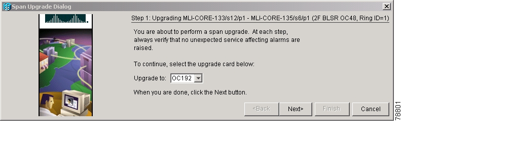
Note
Figure 12-1 Span Upgrade Wizard
Caution
Note
Note
Step 8
Stop. You have completed this procedure.
NTP-A95 Upgrade OC-N Spans Manually
Note
Note
Note
Step 1
•
•
•
•
•
•
•
Caution
Step 2
Step 3
Step 4
Note
A four-node BLSR can take up to five minutes to clear all of the BLSROSYNC alarms. Allow extra time for a large BLSR to clear all of the BLSROSYNC alarms. Refer to the Cisco ONS 15454 Troubleshooting Guide for information about alarms.Step 5
•
•
•
•
•
Note
Note
Note
Stop. You have completed this procedure.
![]()
![]()
![]()
![]()
![]()
![]()
![]()
![]()
Posted: Mon Oct 29 05:22:56 PDT 2007
All contents are Copyright © 1992--2007 Cisco Systems, Inc. All rights reserved.
Important Notices and Privacy Statement.