|
|

Table Of Contents
Management Network Connectivity
13.2.1 IP Scenario 1: CTC and ONS 15454s on Same Subnet
13.2.2 IP Scenario 2: CTC and ONS 15454 Nodes Connected to a Router
13.2.3 IP Scenario 3: Using Proxy ARP to Enable an ONS 15454 Gateway
13.2.4 IP Scenario 4: Default Gateway on a CTC Computer
13.2.5 IP Scenario 5: Using Static Routes to Connect to LANs
13.2.6 IP Scenario 6: Using OSPF
13.2.7 IP Scenario 7: Provisioning the ONS 15454 SOCKS Proxy Server
13.2.8 IP Scenario 8: Dual GNEs on a Subnet
13.2.9 IP Scenario 9: IP Addressing with Secure Mode Enabled
13.7 TCP/IP and OSI Networking
13.7.1 Point-to-Point Protocol
13.7.2 Link Access Protocol on the D Channel
13.7.3 OSI Connectionless Network Service
13.7.6 TCP/IP and OSI Mediation
13.7.9 OSI/IP Networking Scenarios
13.7.10 Provisioning OSI in CTC
Management Network Connectivity
This chapter provides an overview of ONS 15454 data communications network (DCN) connectivity. Cisco Optical Networking System (ONS) network communication is based on IP, including communication between Cisco Transport Controller (CTC) computers and ONS 15454 nodes, and communication among networked ONS 15454 nodes. The chapter provides scenarios showing Cisco ONS 15454 nodes in common IP network configurations as well as information about provisionable patchcords, the IP routing table, external firewalls, and open gateway network element (GNE) networks.
Although ONS 15454 DCN communication is based on IP, ONS 15454 nodes can be networked to equipment that is based on the Open System Interconnection (OSI) protocol suites. This chapter also describes the ONS 15454 OSI implementation and provides scenarios that show how the ONS 15454 can be networked within a mixed IP and OSI environment.
Note
This chapter does not provide a comprehensive explanation of IP networking concepts and procedures, nor does it provide IP addressing examples to meet all networked scenarios. For ONS 15454 networking setup instructions, refer to the "Turn Up a Node" chapter of the Cisco ONS 15454 Procedure Guide.
Chapter topics include:
•
Note
13.1 IP Networking Overview
ONS 15454s can be connected in many different ways within an IP environment:
•
•
•
•
•
•
13.2 IP Addressing Scenarios
ONS 15454 IP addressing generally has eight common scenarios or configurations. Use the scenarios as building blocks for more complex network configurations. Table 13-1 provides a general list of items to check when setting up ONS 15454 nodes in IP networks.
The TCC2P card secure mode option allows two IP addresses to be provisioned for the node: one for the backplane LAN port and one for the TCC2P LAN (TCP/IP) port. Secure mode IP addressing examples are provided in the "IP Scenario 9: IP Addressing with Secure Mode Enabled" section. IP addresses shown in the other scenarios assume that secure mode is not enabled. If secure mode is enabled, the IP addresses shown in the examples apply to the backplane LAN port. See the "IP Scenario 9: IP Addressing with Secure Mode Enabled" section for information about secure mode, repeater (single IP address) mode, and configuration locks.
13.2.1 IP Scenario 1: CTC and ONS 15454s on Same Subnet
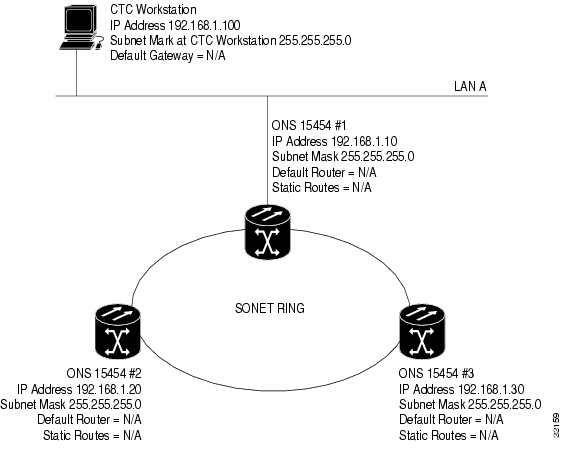
IP Scenario 1 shows a basic ONS 15454 LAN configuration ( Figure 13-1). The ONS 15454s and CTC computer reside on the same subnet. All ONS 15454s connect to LAN A, and all ONS 15454s have DCC connections.
Figure 13-1 IP Scenario 1: CTC and ONS 15454s on Same Subnet
13.2.2 IP Scenario 2: CTC and ONS 15454 Nodes Connected to a Router
In IP Scenario 2 the CTC computer resides on a subnet (192.168.1.0) and attaches to LAN A ( Figure 13-2). The ONS 15454s reside on a different subnet (192.168.2.0) and attach to LAN B. A router connects LAN A to LAN B. The IP address of router interface A is set to LAN A (192.168.1.1), and the IP address of router interface B is set to LAN B (192.168.2.1).
On the CTC computer, the default gateway is set to router interface A. If the LAN uses Dynamic Host Configuration Protocol (DHCP), the default gateway and IP address are assigned automatically. In the Figure 13-2 example, a DHCP server is not available.
Figure 13-2 IP Scenario 2: CTC and ONS 15454 Nodes Connected to a Router
13.2.3 IP Scenario 3: Using Proxy ARP to Enable an ONS 15454 Gateway
ARP matches higher-level IP addresses to the physical addresses of the destination host. It uses a lookup table (called ARP cache) to perform the translation. When the address is not found in the ARP cache, a broadcast is sent out on the network with a special format called the ARP request. If one of the machines on the network recognizes its own IP address in the request, it sends an ARP reply back to the requesting host. The reply contains the physical hardware address of the receiving host. The requesting host stores this address in its ARP cache so that all subsequent datagrams (packets) to this destination IP address can be translated to a physical address.
Proxy ARP enables one LAN-connected ONS 15454 to respond to the ARP request for ONS 15454s not connected to the LAN. (ONS 15454 proxy ARP requires no user configuration.) For this to occur, the DCC-connected ONS 15454s must reside on the same subnet. When a LAN device sends an ARP request to an ONS 15454 that is not connected to the LAN, the gateway ONS 15454 returns its MAC address to the LAN device. The LAN device then sends the datagram for the remote ONS 15454 to the MAC address of the proxy ONS 15454. The proxy ONS 15454 uses its routing table to forward the datagram to the non-LAN ONS 15454.
IP Scenario 3 is similar to IP Scenario 1, but only one ONS 15454 (1) connects to the LAN ( Figure 13-3). Two ONS 15454s (2 and 3) connect to ONS 15454 1 through the SONET DCC. Because all three ONS 15454s are on the same subnet, proxy ARP enables ONS 15454 1 to serve as a gateway for ONS 15454 2 and 3.
Note
Figure 13-3 IP Scenario 3: Using Proxy ARP
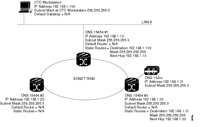
You can also use proxy ARP to communicate with hosts attached to the craft Ethernet ports of DCC-connected nodes ( Figure 13-4). The node with an attached host must have a static route to the host. Static routes are propagated to all DCC peers using OSPF. The existing proxy ARP node is the gateway for additional hosts. Each node examines its routing table for routes to hosts that are not connected to the DCC network but are within the subnet. The existing proxy server replies to ARP requests for these additional hosts with the node MAC address. The existence of the host route in the routing table ensures that the IP packets addressed to the additional hosts are routed properly. Other than establishing a static route between a node and an additional host, no provisioning is necessary. The following restrictions apply:
•
•
In Figure 13-4, Node 1 announces to Node 2 and 3 that it can reach the CTC host. Similarly, Node 3 announces that it can reach the ONS 152xx. The ONS 152xx is shown as an example; any network element (NE) can be set up as an additional host.
Figure 13-4 IP Scenario 3: Using Proxy ARP with Static Routing
13.2.4 IP Scenario 4: Default Gateway on a CTC Computer
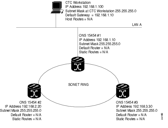
IP Scenario 4 is similar to IP Scenario 3, but Nodes 2 and 3 reside on different subnets, 192.168.2.0 and 192.168.3.0, respectively ( Figure 13-5). Node 1 and the CTC computer are on subnet 192.168.1.0. Proxy ARP is not used because the network includes different subnets. For the CTC computer to communicate with Nodes 2 and 3, Node 1 is entered as the default gateway on the CTC computer.
Figure 13-5 IP Scenario 4: Default Gateway on a CTC Computer
13.2.5 IP Scenario 5: Using Static Routes to Connect to LANs
Static routes are used for two purposes:
•
•
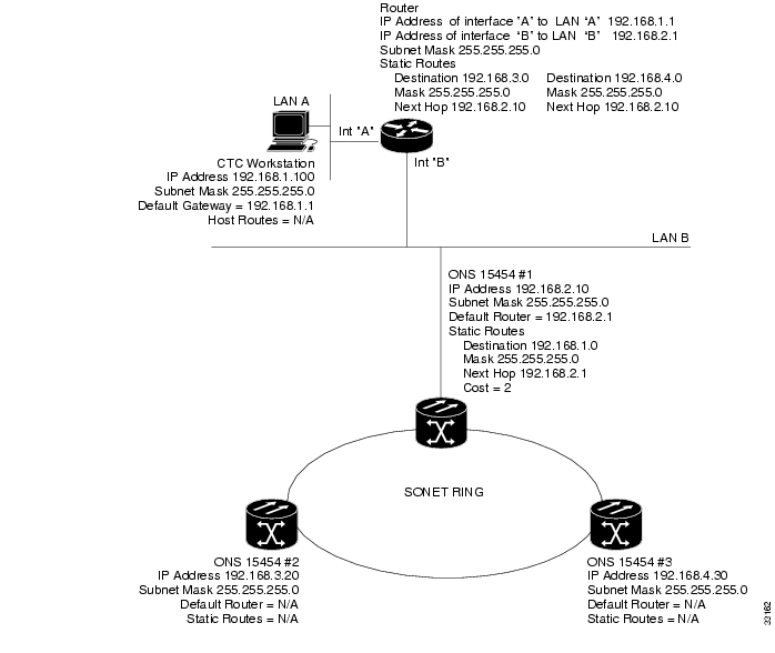
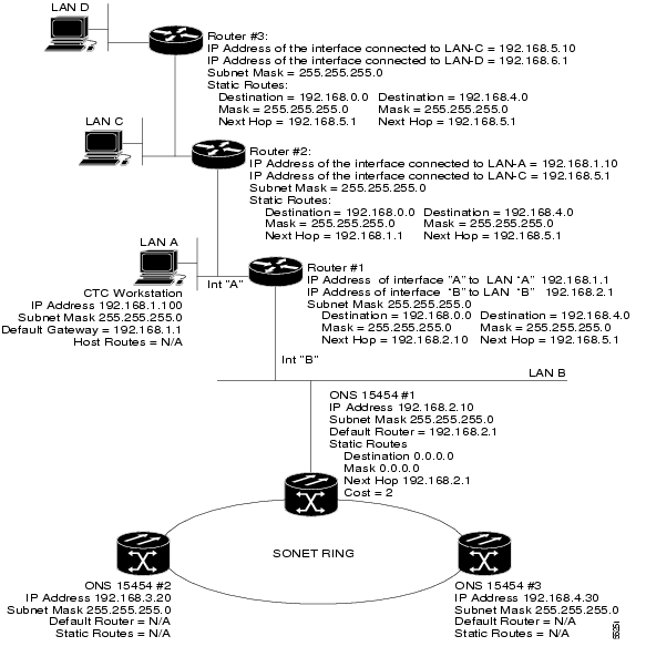
In Figure 13-6, one CTC residing on subnet 192.168.1.0 connects to a router through interface A. (The router is not set up with OSPF.) ONS 15454s residing on different subnets are connected through Node 1 to the router through interface B. Because Nodes 2 and 3 are on different subnets, proxy ARP does not enable Node 1 as a gateway. To connect to the CTC computer on LAN A (subnet 192.168.1.0), you must create a static route on Node 1. You must also manually add static routes between the CTC computer on LAN A and Nodes 2 and 3 because these nodes are on different subnets.
Figure 13-6 IP Scenario 5: Static Route With One CTC Computer Used as a Destination
The destination and subnet mask entries control access to the ONS 15454s:
•
•
•
The IP address of router interface B is entered as the next hop, and the cost (number of hops from source to destination) is 2. You must manually add static routes between the CTC computers on LAN A, B, and C and Nodes 2 and 3 because these nodes are on different subnets.
Figure 13-7 IP Scenario 5: Static Route With Multiple LAN Destinations
13.2.6 IP Scenario 6: Using OSPF
Open Shortest Path First (OSPF) is a link state Internet routing protocol. Link state protocols use a "hello protocol" to monitor their links with adjacent routers and to test the status of their links to their neighbors. Link state protocols advertise their directly connected networks and their active links. Each link state router captures the link state "advertisements" and puts them together to create a topology of the entire network or area. From this database, the router calculates a routing table by constructing a shortest path tree. Routes are recalculated when topology changes occur.
ONS 15454s use the OSPF protocol in internal ONS 15454 networks for node discovery, circuit routing, and node management. You can enable OSPF on the ONS 15454s so that the ONS 15454 topology is sent to OSPF routers on a LAN. Advertising the ONS 15454 network topology to LAN routers eliminates the need to manually enter static routes for ONS 15454 subnetworks. Figure 13-8 shows a network enabled for OSPF. Figure 13-9 shows the same network without OSPF. Static routes must be manually added to the router for CTC computers on LAN A to communicate with Nodes 2 and 3 because these nodes reside on different subnets.
OSPF divides networks into smaller regions, called areas. An area is a collection of networked end systems, routers, and transmission facilities organized by traffic patterns. Each OSPF area has a unique ID number, known as the area ID. Every OSPF network has one backbone area called "area 0." All other OSPF areas must connect to area 0.
When you enable an ONS 15454 OSPF topology for advertising to an OSPF network, you must assign an OSPF area ID in decimal format to the ONS 15454 network. Coordinate the area ID number assignment with your LAN administrator. All DCC-connected ONS 15454s should be assigned the same OSPF area ID.
Figure 13-8 IP Scenario 6: OSPF Enabled
Figure 13-9 IP Scenario 6: OSPF Not Enabled
13.2.7 IP Scenario 7: Provisioning the ONS 15454 SOCKS Proxy Server
The ONS 15454 SOCKS proxy is an application that allows an ONS 15454 node to serve as an internal gateway between a private enterprise network and the ONS 15454 network. (SOCKS is a standard proxy protocol for IP-based applications developed by the Internet Engineering Task Force.) Access is allowed from the private network to the ONS 15454 network, but access is denied from the ONS 15454 network to the private network. For example, you can set up a network so that field technicians and network operations center (NOC) personnel can both access the same ONS 15454s while preventing the field technicians from accessing the NOC LAN. To do this, one ONS 15454 is provisioned as a gateway network element (GNE) and the other ONS 15454s are provisioned as end network elements (ENEs). The GNE ONS 15454 tunnels connections between CTC computers and ENE ONS 15454s, providing management capability while preventing access for non-ONS 15454 management purposes.
The ONS 15454 gateway setting performs the following tasks:
•
•
•
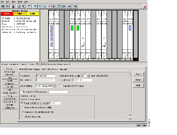
The ONS 15454 SOCKS proxy server is provisioned using the Enable SOCKS proxy server on port check box on the Provisioning > Network > General tab ( Figure 13-10).
Figure 13-10 SOCKS Proxy Server Gateway Settings
If checked, the ONS 15454 serves as a proxy for connections between CTC clients and ONS 15454s that are DCC-connected to the proxy ONS 15454. The CTC client establishes connections to DCC-connected nodes through the proxy node. The CTC client can connect to nodes that it cannot directly reach from the host on which it runs. If not selected, the node does not proxy for any CTC clients, although any established proxy connections continue until the CTC client exits. In addition, you can set the SOCKS proxy server as an ENE or a GNE:
Note
•
In addition, firewall is enabled, which means that the node prevents IP traffic from being routed between the DCC and the LAN port. The ONS 15454 can communicate with machines connected to the LAN port or connected through the DCC. However, the DCC-connected machines cannot communicate with the LAN-connected machines, and the LAN-connected machines cannot communicate with the DCC-connected machines. A CTC client using the LAN to connect to the firewall-enabled node can use the proxy capability to manage the DCC-connected nodes that would otherwise be unreachable. A CTC client connected to a DCC-connected node can only manage other DCC-connected nodes and the firewall itself.
•
•
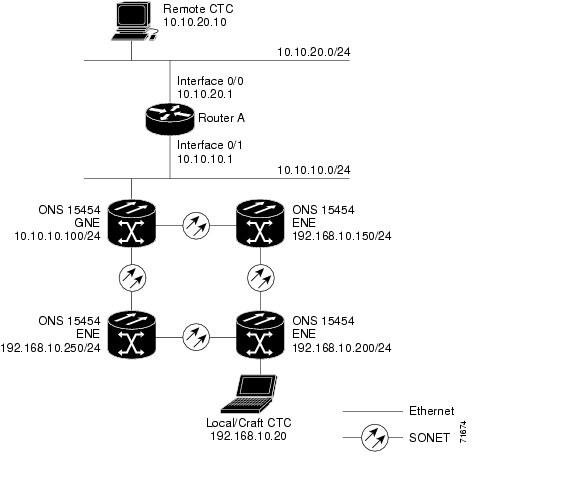
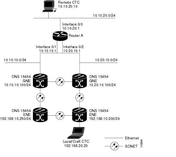
Figure 13-11 shows an ONS 15454 SOCKS proxy server implementation. A GNE ONS 15454 is connected to a central office LAN and to ENE ONS 15454s. The central office LAN is connected to a NOC LAN, which has CTC computers. Both the NOC CTC computer and the craft technicians must be able to access the ONS 15454 ENEs. However, the craft technicians must be prevented from accessing or seeing the NOC or central office LANs.
In the example, the ONS 15454 GNE is assigned an IP address within the central office LAN and is physically connected to the LAN through its LAN port. ONS 15454 ENEs are assigned IP addresses that are outside the central office LAN and are given private network IP addresses. If the ONS 15454 ENEs are collocated, the craft LAN ports could be connected to a hub. However, the hub should have no other network connections.
Figure 13-11 IP Scenario 7: ONS 15454 SOCKS Proxy Server with GNE and ENEs on the Same Subnet
Table 13-2 shows recommended settings for ONS 15454 GNEs and ENEs in the configuration shown in Figure 13-11.
Figure 13-12 shows the same SOCKS proxy server implementation with ONS 15454 ENEs on different subnets. Figure 13-13 shows the implementation with ONS 15454 ENEs in multiple rings. In each example, ONS 15454 GNEs and ENEs are provisioned with the settings shown in Table 13-2.
Figure 13-12 IP Scenario 7: ONS 15454 SOCKS Proxy Server with GNE and ENEs on Different Subnets
Figure 13-13 IP Scenario 7: ONS 15454 SOCKS Proxy Server With ENEs on Multiple Rings
Table 13-3 shows the rules that the ONS 15454 follows to filter packets for the firewall when nodes are configured as ENEs and GNEs.
If the packet is addressed to the ONS 15454 node, additional rules, shown in Table 13-4, are applied. Rejected packets are silently discarded.
Table 13-4 SOCKS Proxy Server Firewall Filtering Rules When Packet Addressed to the ONS 15454
TCC2/TCC2P Ethernet interface
•
•
DCC interface
•
•
•
•
•
•
•
1 UDP = User Datagram Protocol
2 TCP = Transmission Control Protocol
3 ICMP = Internet Control Message Protocol
If you implement the SOCKS proxy server, note that all DCC-connected ONS 15454s on the same Ethernet segment must have the same gateway setting. Mixed values produce unpredictable results, and might leave some nodes unreachable through the shared Ethernet segment.
If nodes become unreachable, correct the setting with one of the following actions:
•
•
13.2.8 IP Scenario 8: Dual GNEs on a Subnet
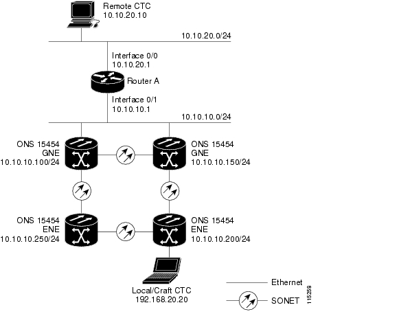
The ONS 15454 provides GNE load balancing, which allows CTC to reach ENEs over multiple GNEs without the ENEs being advertised over OSPF. This feature allows a network to quickly recover from the loss of a GNE, even if the GNE is on a different subnet. If a GNE fails, all connections through that GNE fail. CTC disconnects from the failed GNE and from all ENEs for which the GNE was a proxy, and then reconnects through the remaining GNEs. GNE load balancing reduces the dependency on the launch GNE and DCC bandwidth, both of which enhance CTC performance. Figure 13-14 shows a network with dual GNEs on the same subnet.
Figure 13-14 IP Scenario 8: Dual GNEs on the Same Subnet
Figure 13-15 shows a network with dual GNEs on different subnets.
Figure 13-15 IP Scenario 8: Dual GNEs on Different Subnets
13.2.9 IP Scenario 9: IP Addressing with Secure Mode Enabled
The TCC2 card and TCC2P card both default to repeater mode. In this mode, the front and back Ethernet (LAN) ports share a single MAC address and IP address. TCC2P cards allow you to place a node in secure mode, which prevents a front-access craft port user from accessing the LAN through the backplane port. Secure mode can be locked, which prevents the mode from being altered. To place a node in secure mode or to lock secure node, refer to the "Change Node Settings" chapter in the Cisco ONS 15454 Procedure Guide.
13.2.9.1 Secure Mode Behavior
Changing a TCC2P node from repeater mode to secure mode allows you to provision two IP addresses for the ONS 15454 and causes the node to assign the ports different MAC addresses. In secure mode, one IP address is provisioned for the ONS 15454 backplane LAN port, and the other IP address is provisioned for the TCC2P Ethernet port. Both addresses reside on different subnets, providing an additional layer of separation between the craft access port and the ONS 15454 LAN. If secure mode is enabled, the IP addresses provisioned for both TCC2P TCP/IP LAN ports must follow general IP addressing guidelines and must reside on different subnets from each other and the default router IP address.
In secure mode, the IP address assigned to the backplane LAN port becomes a private address, which connects the node to an Operations Support System (OSS) through a central office LAN or private enterprise network. A Superuser can configure the node to hide or reveal the backplane's LAN IP address in CTC, the routing table, or autonomous message reports.
In repeater mode, a node can be a GNE or ENE. Placing the node into secure mode automatically turns on SOCKS proxy and defaults the node to GNE status. However, the node can be changed back to an ENE. In repeater mode, an ENE's SOCKS proxy can be disabled—effectively isolating the node beyond the LAN firewall—but it cannot be disabled in secure mode.To change a node's GNE or ENE status and disable the SOCKS proxy, refer to the "Turn Up a Node" chapter in the Cisco ONS 15454 Procedure Guide.
Caution
Note
Note
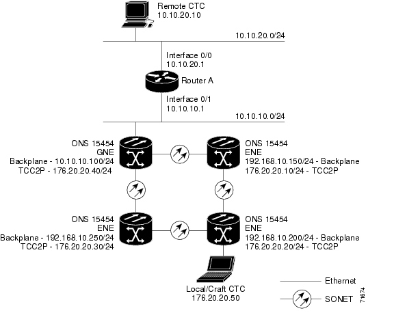
Figure 13-16 shows an example of secure-mode ONS 15454 nodes with front-access Ethernet port addresses that reside on the same subnet.
Figure 13-16 . IP Scenario 9: ONS 15454 GNE and ENEs on the Same Subnet with Secure Mode Enabled
Figure 13-17 shows an example of ONS 15454 nodes connected to a router with secure mode enabled. In each example, the node's TCC2P port address (node address) resides on a different subnet from the node backplane address.
Figure 13-17 IP Scenario 9: ONS 15454 GNE and ENEs on Different Subnets with Secure Mode Enabled
13.2.9.2 Secure Node Locked and Unlocked Behavior
Secure mode can be locked or unlocked on a node operating in secure mode. The default status is unlocked, and only a Superuser can issue a lock. When secure mode is locked, the node's configuration (including Ethernet port status) and lock status cannot be changed by any network user. To have a secure node's lock removed, contact Cisco Technical Support to arrange a Return Material Authorization (RMA) for the shelf assembly. See the "Obtaining Documentation, Obtaining Support, and Security Guidelines" section on page xlviii as needed. Enabling a lock makes a permanent change to the shelf's electrically erasable programmable read-only memory (EEPROM).
Note
A node's configuration lock is maintained if the active TCC2P card's database is reloaded. For example, if you attempt to load an unlocked node database onto a locked node's standby TCC2P card for transfer to the active TCC2P card (an action that is not recommended), the unlocked node's status (through the uploaded database) will not override the node's lock status. If you attempt to load a locked database onto the standby TCC2P card of an unlocked secure node, the active TCC2P card will upload the database. If the uploaded defaults indicate a locked status, this will cause the node to become locked. If a software load has been customized before a lock is enabled, all lockable provisioning features are permanently set to the customized NE defaults provided in the load and cannot be changed by any user.
13.3 Provisionable Patchcords
A provisionable patchcord is a user-provisioned link that is advertised by OSPF throughout the network. Provisionable patchcords, also called virtual links, are needed in the following situations:
•
•
•
•
Provisionable patchcords are required on both ends of a physical link. The provisioning at each end includes a local patchcord ID, slot/port information, remote IP address, and remote patchcord ID. Patchcords appear as dashed lines in CTC network view.
An optical patchcord must be provisioned between an OCH filter and an OCH trunk port. In A manually provisioned patchcord automatically tunes the transponder (TXP) or muxponder (MXP) trunk as an OCH filter if the TXP or MXP is set to autoprovisioning at the first tunable wavelength. You can automatically tune internal and external (virtual link) patchcords in CTC. In TL1, only internal patchcords can be provisioned.
Table 13-5 lists the supported card combinations for client and trunk ports in a provisionable patchcord.
Note
Table 13-6 lists the supported card combinations for client-to-client ports in a patchcord.
Table 13-7 lists the supported card combinations for trunk-to-trunk ports in a patchcord.
Optical ports have the following requirements when used in a provisionable patchcord:
•
•
•
TXP and MXP ports have the following requirements when used in a provisionable patchcord:
•
•
•
DWDM cards support provisionable patchcords only on optical channel ports. Each DWDM optical channel port can have only one provisionable patchcord.
Note
13.4 Routing Table
ONS 15454 routing information appears on the Maintenance > Routing Table tab. The routing table provides the following information:
•
•
•
•
•
–
–
–
Table 13-8 shows sample routing table entries for an ONS 15454.
Entry 1 shows the following:
•
•
•
•
Entry 2 shows the following:
•
•
•
•
Entry 3 shows the following:
•
•
•
•
Entry 4 shows the following:
•
•
•
•
Entry 5 shows a DCC-connected node that is accessible through a node that is not directly connected:
•
•
•
•
13.5 External Firewalls
This section provides sample access control lists (ACLs) for external firewalls. Table 13-9 lists the ports that are used by the TCC2/TCC2P card.
Table 13-9 Ports Used by the TCC2/TCC2P
0
Never used
D
20
FTP
D
21
FTP control
D
22
SSH (Secure Shell)
D
23
Telnet
D
80
HTTP
D
111
SUNRPC (Sun Remote Procedure Call)
NA
161
SNMP traps destinations
D
162
SNMP traps destinations
D
513
rlogin
D
683
CORBA IIOP2
OK
1080
Proxy server (socks)
D
2001-2017
I/O card Telnet
D
2018
DCC processor on active TCC2/TCC2P
D
2361
TL1
D
3082
Raw TL1
D
3083
TL1
D
5001
BLSR3 server port
D
5002
BLSR client port
D
7200
SNMP alarm input port
D
9100
EQM port
D
9401
TCC boot port
D
9999
Flash manager
D
10240-12287
Proxy client
D
57790
Default TCC listener port
OK
1 D = deny, NA = not applicable, OK = do not deny
2 CORBA IIOP = Common Object Request Broker Architecture Internet Inter-ORB Protocol
3 BLSR = bidirectional line switched ring
The following ACL example shows a firewall configuration when the SOCKS proxy server gateway setting is not enabled. In the example, the CTC workstation's address is 192.168.10.10. and the ONS 15454 address is 10.10.10.100. The firewall is attached to the GNE, so inbound is CTC to the GNE and outbound is from the GNE to CTC. The CTC CORBA Standard constant is 683 and the TCC CORBA Default is TCC Fixed (57790).
access-list 100 remark *** Inbound ACL, CTC -> NE ***access-list 100 remarkaccess-list 100 permit tcp host 192.168.10.10 host 10.10.10.100 eq wwwaccess-list 100 remark *** allows initial contact with ONS 15454 using http (port 80) ***access-list 100 remarkaccess-list 100 permit tcp host 192.168.10.10 host 10.10.10.100 eq 57790access-list 100 remark *** allows CTC communication with ONS 15454 GNE (port 57790) ***access-list 100 remarkaccess-list 100 permit tcp host 192.168.10.10 host 10.10.10.100 establishedaccess-list 100 remark *** allows ACKs back from CTC to ONS 15454 GNE ***access-list 101 remark *** Outbound ACL, NE -> CTC ***access-list 101 remarkaccess-list 101 permit tcp host 10.10.10.100 host 192.168.10.10 eq 683access-list 101 remark *** allows alarms etc., from the 15454 (random port) to the CTC workstation (port 683) ***access-list 100 remarkaccess-list 101 permit tcp host 10.10.10.100 host 192.168.10.10 establishedaccess-list 101 remark *** allows ACKs from the 15454 GNE to CTC ***The following ACL example shows a firewall configuration when the SOCKS proxy server gateway setting is enabled. As with the first example, the CTC workstation address is 192.168.10.10 and the ONS 15454 address is 10.10.10.100. The firewall is attached to the GNE, so inbound is CTC to the GNE and outbound is from the GNE to CTC. CTC CORBA Standard constant is 683 and the TCC CORBA Default is TCC Fixed (57790).
access-list 100 remark *** Inbound ACL, CTC -> NE ***access-list 100 remarkaccess-list 100 permit tcp host 192.168.10.10 host 10.10.10.100 eq wwwaccess-list 100 remark *** allows initial contact with the 15454 using http (port 80) ***access-list 100 remarkaccess-list 100 permit tcp host 192.168.10.10 host 10.10.10.100 eq 1080access-list 100 remark *** allows CTC communication with the 15454 GNE (port 1080) ***access-list 100 remarkaccess-list 101 remark *** Outbound ACL, NE -> CTC ***access-list 101 remarkaccess-list 101 permit tcp host 10.10.10.100 host 192.168.10.10 establishedaccess-list 101 remark *** allows ACKs from the 15454 GNE to CTC ***13.6 Open GNE
The ONS 15454 can communicate with non-ONS nodes that do not support Point-to-Point Protocol (PPP) vendor extensions or OSPF type 10 opaque link-state advertisements (LSA), both of which are necessary for automatic node and link discovery. An open GNE configuration allows the DCC-based network to function as an IP network for non-ONS nodes.
To configure an open GNE network, you can provision SDCC, LDCC, and GCC terminations to include a far-end, non-ONS node using either the default IP address of 0.0.0.0 or a specified IP address. You provision a far-end, non-ONS node by checking the Far End is Foreign check box during SDCC, LDCC, and GCC creation. The default 0.0.0.0 IP address allows the far-end, non-ONS node to provide the IP address; if you set an IP address other than 0.0.0.0, a link is established only if the far-end node identifies itself with that IP address, providing an extra level of security.
By default, the SOCKS proxy server only allows connections to discovered ONS peers and the firewall blocks all IP traffic between the DCC network and LAN. You can, however, provision proxy tunnels to allow up to 12 additional destinations for SOCKS version 5 connections to non-ONS nodes. You can also provision firewall tunnels to allow up to 12 additional destinations for direct IP connectivity between the DCC network and the LAN. Proxy and firewall tunnels include both a source and destination subnet. The connection must originate within the source subnet and terminate within the destination subnet before either the SOCKS connection or IP packet flow is allowed.
To set up proxy and firewall subnets in CTC, use the Provisioning > Network > Proxy and Firewalls subtabs. The availability of proxy and/or firewall tunnels depends on the network access settings of the node:
•
•
•
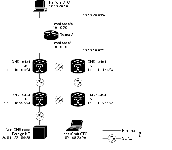
Figure 13-18 shows an example of a foreign node connected to the DCC network. Proxy and firewall tunnels are useful in this example because the GNE would otherwise block IP access between the PC and the foreign node.
Figure 13-18 Proxy and Firewall Tunnels for Foreign Terminations
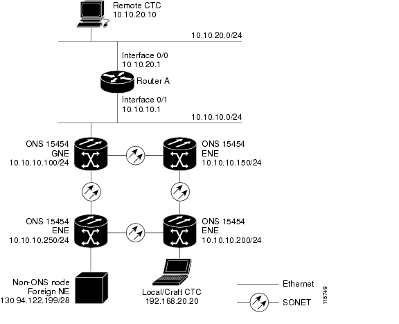
Figure 13-19 shows a remote node connected to an ENE Ethernet port. Proxy and firewall tunnels are useful in this example because the GNE would otherwise block IP access between the PC and foreign node. This configuration also requires a firewall tunnel on the ENE.
Figure 13-19 Foreign Node Connection to an ENE Ethernet Port
13.7 TCP/IP and OSI Networking
ONS 15454 DCN communication is based on the TCP/IP protocol suite. However, ONS 15454s can also be networked with equipment that uses the OSI protocol suite. While TCP/IP and OSI protocols are not directly compatible, they do have the same objectives and occupy similar layers of the OSI reference model. Table 13-10 shows the protocols and mediation processes that are involved when TCP/IP-based NEs are networked with OSI-based NEs.
Table 13-10 TCP/IP and OSI Protocols
Layer 7 Application
•
•
•
•
•
•
•
•
•
•
•
Layer 6 Presentation
•
Layer 5 Session
•
Layer 4 Transport
•
•
•
•
Layer 3 Network
•
•
•
•
•
Layer 2 Data link
•
•
•
Layer 1 Physical
DCC, LAN, fiber, electrical
DCC, LAN, fiber, electrical
1 TARP = TID Address Resolution Protocol
2 FTAM = File Transfer and Access Management
3 ACSE = association-control service element
4 T-TD = TL1-Translation Device
5 FT-TD = File Transfer—Translation Device
6 PST = Presentation layer
7 CLNS = Connectionless Network Layer Service
8 CLNP = Connectionless Network Layer Protocol
9 ES-IS = End System-to-Intermediate System
10 IS-IS = Intermediate System-to-Intermediate System
11 LAP-D = Link Access Protocol on the D Channel
13.7.1 Point-to-Point Protocol
PPP is a data link (Layer 2) encapsulation protocol that transports datagrams over point-to-point links. Although PPP was developed to transport IP traffic, it can carry other protocols including the OSI CLNP. PPP components used in the transport of OSI include:
•
•
CTC automatically enables IP over PPP whenever you create an SDCC or LDCC. The SDCC or LDCC can be provisioned to support OSI over PPP.
13.7.2 Link Access Protocol on the D Channel
LAP-D is a data link protocol used in the OSI protocol stack. LAP-D is assigned when you provision an ONS 15454 SDCC as OSI-only. Provisionable LAP-D parameters include:
•
–
–
•
•
Note
•
–
–
Fixed values are assigned to the following LAP-D parameters:
•
•
•
13.7.3 OSI Connectionless Network Service
OSI connectionless network service is implemented by using the Connectionless Network Protocol (CLNP) and Connectionless Network Service (CLNS). CLNP and CLNS are described in the ISO 8473 standard. CLNS provides network layer services to the transport layer through CLNP. CLNS does not perform connection setup or termination because paths are determined independently for each packet that is transmitted through a network. CLNS relies on transport layer protocols to perform error detection and correction.
CLNP is an OSI network layer protocol that carries upper-layer data and error indications over connectionless links. CLNP provides the interface between the CLNS and upper layers. CLNP performs many of the same services for the transport layer as IP. The CLNP datagram is very similar to the IP datagram. It provides mechanisms for fragmentation (data unit identification, fragment/total length, and offset). Like IP, a checksum computed on the CLNP header verifies that the information used to process the CLNP datagram is transmitted correctly, and a lifetime control mechanism (Time to Live) limits the amount of time a datagram is allowed to remain in the system.
CLNP uses network service access points (NSAPs) to identify network devices. The CLNP source and destination addresses are NSAPs. In addition, CLNP uses a network element title (NET) to identify a network-entity in an end system (ES) or intermediate system (IS). NETs are allocated from the same name space as NSAP addresses. Whether an address is an NSAP address or a NET depends on the network selector value in the NSAP.
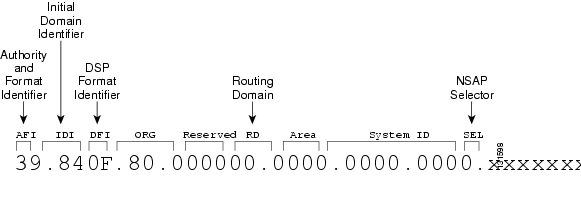
The ONS 15454 supports the ISO Data Country Code (ISO-DCC) NSAP address format as specified in ISO 8348. The NSAP address is divided into an initial domain part (IDP) and a domain-specific part (DSP). NSAP fields are shown in Table 13-11. NSAP field values are in hexadecimal format. All NSAPs are editable. Shorter NSAPs can be used. However NSAPs for all NEs residing within the same OSI network area usually have the same NSAP format.
Table 13-11 NSAP Fields
AFI
Authority and format identifier
Specifies the NSAP address format. The initial value is 39 for the ISO-DCC address format.
IDI
Initial domain identifier
Specifies the country code. The initial value is 840F, the United States country code padded with an F.
DFI
DSP format identifier
Specifies the DSP format. The initial value is 80, indicating the DSP format follows American National Standards Institute (ANSI) standards.
ORG
Organization
Organization identifier. The initial value is 000000.
Reserved
Reserved
Reserved NSAP field. The Reserved field is normally all zeros (0000).
RD
Routing domain
Defines the routing domain. The initial value is 0000.
AREA
Area
Identifies the OSI routing area to which the node belongs. The initial value is 0000.
System
System identifier
The ONS 15454 system identifier is set to its IEEE 802.3 MAC address. Each ONS 15454 supports three OSI virtual routers. Each router NSAP system identifier is the ONS 15454 IEEE 802.3 MAC address + n, where n = 0 to 2. For the primary virtual router, n = 0.
SEL
Selector
The selector field directs the protocol data units (PDUs) to the correct destination using the CLNP network layer service. Selector values supported by the ONS 15454 include:
•
•
•
•
•
•
NSELs are only advertised when the node is configured as an ES. They are not advertised when a node is configured as an IS. Tunnel NSELs are not advertised until a tunnel is created.
Figure 13-20 shows the ISO-DCC NSAP address with the default values delivered with the ONS 15454. The System ID is automatically populated with the node MAC address.
Figure 13-20 ISO-DCC NSAP Address
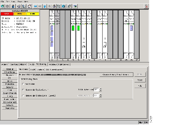
The ONS 15454 main NSAP address is shown on the node view Provisioning > OSI > Main Setup subtab ( Figure 13-21).
Figure 13-21 OSI Main Setup
This address is also the Router 1 primary manual area address, which is viewed and edited on the Provisioning > OSI > Routers subtab. See the "OSI Virtual Routers" section for information about the OSI router and manual area addresses in CTC.
13.7.4 OSI Routing
OSI architecture includes ESs and ISs. The OSI routing scheme includes:
•
•
•
In OSI networking, discovery is based on announcements. An ES uses the ES-IS protocol end system hello (ESH) message to announce its presence to ISs and ESs connected to the same network. Any ES or IS that is listening for ESHs gets a copy. ISs store the NSAP address and the corresponding subnetwork address pair in routing tables. ESs might store the address, or they might wait to be informed by ISs when they need such information.
An IS composes intermediate system hello (ISH) messages to announce its configuration information to ISs and ESs that are connected to the same broadcast subnetwork. Like the ESHs, the ISH contains the addressing information for the IS (the NET and the subnetwork point-of-attachment address [SNPA]) and a holding time. ISHs might also communicate a suggested ES configuration time recommending a configuration timer to ESs.
The exchange of ISHs is called neighbor greeting or initialization. Each router learns about the other routers with which they share direct connectivity. After the initialization, each router constructs a link-state packet (LSP). The LSP contains a list of the names of the IS's neighbors and the cost to reach each of the neighbors. Routers then distribute the LSPs to all of the other routers. When all LSPs are propagated to all routers, each router has a complete map of the network topology (in the form of LSPs). Routers use the LSPs and the SPF algorithm to compute routes to every destination in the network.
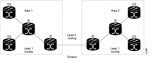
OSI networks are divided into areas and domains. An area is a group of contiguous networks and attached hosts that is designated as an area by a network administrator. A domain is a collection of connected areas. Routing domains provide full connectivity to all ESs within them. Routing within the same area is known as Level 1 routing. Routing between two areas is known as Level 2 routing. LSPs that are exchanged within a Level 1 area are called L1 LSPs. LSPs that are exchanged across Level 2 areas are called L2 LSPs. Figure 13-22 shows an example of Level 1 and Level 2 routing.
Figure 13-22 Level 1 and Level 2 OSI Routing
When you provision an ONS 15454 for a network with NEs that use both the TCP/IP and OSI protocol stacks, you will provision it as one of the following:
•
•
•
13.7.4.1 End System-to-Intermediate System Protocol
ES-IS is an OSI protocol that defines how ESs (hosts) and ISs (routers) learn about each other. ES-IS configuration information is transmitted at regular intervals through the ES and IS hello messages. The hello messages contain the subnetwork and network layer addresses of the systems that generate them.
The ES-IS configuration protocol communicates both OSI network layer addresses and OSI subnetwork addresses. OSI network layer addresses identify either the NSAP, which is the interface between OSI Layer 3 and Layer 4, or the NET, which is the network layer entity in an OSI IS. OSI SNPAs are the points at which an ES or IS is physically attached to a subnetwork. The SNPA address uniquely identifies each system attached to the subnetwork. In an Ethernet network, for example, the SNPA is the 48-bit MAC address. Part of the configuration information transmitted by ES-IS is the NSAP-to-SNPA or NET-to-SNPA mapping.
13.7.4.2 Intermediate System-to-Intermediate System Protocol
IS-IS is an OSI link-state hierarchical routing protocol that floods the network with link-state information to build a complete, consistent picture of a network topology. IS-IS distinguishes between Level 1 and Level 2 ISs. Level 1 ISs communicate with other Level 1 ISs in the same area. Level 2 ISs route between Level 1 areas and form an intradomain routing backbone. Level 1 ISs need to know only how to get to the nearest Level 2 IS. The backbone routing protocol can change without impacting the intra-area routing protocol.
OSI routing begins when the ESs discover the nearest IS by listening to ISH packets. When an ES wants to send a packet to another ES, it sends the packet to one of the ISs on its directly attached network. The router then looks up the destination address and forwards the packet along the best route. If the destination ES is on the same subnetwork, the local IS knows this from listening to ESHs and forwards the packet appropriately. The IS also might provide a redirect (RD) message back to the source to tell it that a more direct route is available. If the destination address is an ES on another subnetwork in the same area, the IS knows the correct route and forwards the packet appropriately. If the destination address is an ES in another area, the Level 1 IS sends the packet to the nearest Level 2 IS. Forwarding through Level 2 ISs continues until the packet reaches a Level 2 IS in the destination area. Within the destination area, the ISs forward the packet along the best path until the destination ES is reached.
Link-state update messages help ISs learn about the network topology. Each IS generates an update specifying the ESs and ISs to which it is connected, as well as the associated metrics. The update is then sent to all neighboring ISs, which forward (flood) it to their neighbors, and so on. (Sequence numbers terminate the flood and distinguish old updates from new ones.) Using these updates, each IS can build a complete topology of the network. When the topology changes, new updates are sent.
IS-IS uses a single required default metric with a maximum path value of 1024. The metric is arbitrary and typically is assigned by a network administrator. Any single link can have a maximum value of 64, and path links are calculated by summing link values. Maximum metric values were set at these levels to provide the granularity to support various link types while at the same time ensuring that the shortest-path algorithm used for route computation is reasonably efficient. Three optional IS-IS metrics (costs)—delay, expense, and error—are not supported by the ONS 15454. IS-IS maintains a mapping of the metrics to the quality of service (QoS) option in the CLNP packet header. IS-IS uses the mappings to compute routes through the internetwork.
13.7.5 TARP
TARP is used when TL1 target identifiers (TIDs) must be translated to NSAP addresses. The TID-to-NSAP translation occurs by mapping TIDs to the NETs, then deriving NSAPs from the NETs by using the NSAP selector values ( Table 13-11).
TARP uses a selective PDU propagation methodology in conjunction with a distributed database (that resides within the NEs) of TID-to-NET mappings. TARP allows NEs to translate between TID and NET by automatically exchanging mapping information with other NEs. The TARP PDU is carried by the standard CLNP Data PDU. TARP PDU fields are shown in Table 13-12.
Table 13-12 TARP PDU Fields
TARP Lifetime
tar-lif
2
The TARP time-to-live in hops.
TARP Sequence Number
tar-seq
2
The TARP sequence number used for loop detection.
Protocol Address Type
tar-pro
1
Used to identify the type of protocol address that the TID must be mapped to. The value FE is used to identify the CLNP address type.
TARP Type Code
tar-tcd
1
The TARP Type Code identifies the TARP type of PDU. Five TARP types, shown in Table 13-13, are defined.
TID Target Length
tar-tln
1
The number of octets that are in the tar-ttg field.
TID Originator Length
tar-oln
1
The number of octets that are in the tar-tor field.
Protocol Address Length
tar-pln
1
The number of octets that are in the tar-por field.
TID of Target
tar-ttg
n = 0, 1, 2...
TID value for the target NE.
TID of Originator
tar-tor
n = 0, 1, 2...
TID value of the TARP PDU originator.
Protocol Address of Originator
tar-por
n = 0, 1, 2...
Protocol address (for the protocol type identified in the tar-pro field) of the TARP PDU originator. When the tar-pro field is set to FE (hex), tar-por will contain a CLNP address (that is, the NET).
Table 13-13 shows the TARP PDUs types that govern TARP interaction and routing.
13.7.5.1 TARP Processing
A TARP data cache (TDC) is created at each NE to facilitate TARP processing. In CTC, the TDC is displayed and managed on the node view Maintenance > OSI > TDC subtab. The TDC subtab contains the following TARP PDU fields:
•
•
•
Provisionable timers, shown in Table 13-14, control TARP processing.
Table 13-15 shows the main TARP processes and the general sequence of events that occurs in each process.
13.7.5.2 TARP Loop Detection Buffer
The TARP loop detection buffer (LDB) can be enabled to prevent duplicate TARP PDUs from entering the TDC. When a TARP Type 1, 2, or 4 PDU arrives, TARP checks its LDB for a NET address (tar-por) of the PDU originator match. If no match is found, TARP processes the PDU and assigns a tar-por, tar-seq (sequence) entry for the PDU to the LDB. If the tar-seq is zero, a timer associated with the LDB entry is started using the provisionable LDB entry timer on the node view OSI > TARP > Config tab. If a match exists, the tar-seq is compared to the LDB entry. If the tar-seq is not zero and is less than or equal to the LDB entry, the PDU is discarded. If the tar-seq is greater than the LDB entry, the PDU is processed and the tar-seq field in the LDB entry is updated with the new value. The Cisco ONS 15454 LDB holds approximately 500 entries. The LDB is flushed periodically based on the time set in the LDB Flush timer on the node view OSI > TARP > Config tab.
13.7.5.3 Manual TARP Adjacencies
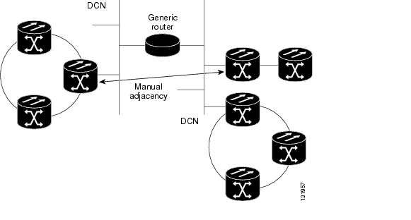
TARP adjacencies can be manually provisioned in networks where ONS 15454s must communicate across routers or non-SONET NEs that lack TARP capability. In CTC, manual TARP adjacencies are provisioned on the node view Provisioning > OSI > TARP > MAT (Manual Area Table) subtab. The manual adjacency causes a TARP request to hop through the general router or non-SONET NE, as shown in Figure 13-23.
Figure 13-23 Manual TARP Adjacencies
13.7.5.4 Manual TID to NSAP Provisioning
TIDs can be manually linked to NSAPs and added to the TDC. Static TDC entries are similar to static routes. For a specific TID, you force a specific NSAP. Resolution requests for that TID always return that NSAP. No TARP network propagation or instantaneous replies are involved. Static entries allow you to forward TL1 commands to NEs that do not support TARP. However, static TDC entries are not dynamically updated, so outdated entries are not removed after the TID or the NSAP changes on the target node.
13.7.6 TCP/IP and OSI Mediation
Two mediation processes facilitate TL1 networking and file transfers between NEs and ONS client computers running TCP/IP and OSI protocol suites:
•
Figure 13-24 T-TD Protocol Flow
•
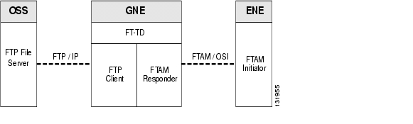
Figure 13-25 FT-TD Protocol Flow
The ONS 15454 uses FT-TD for the following file transfer processes:
•
•
•
13.7.7 OSI Virtual Routers
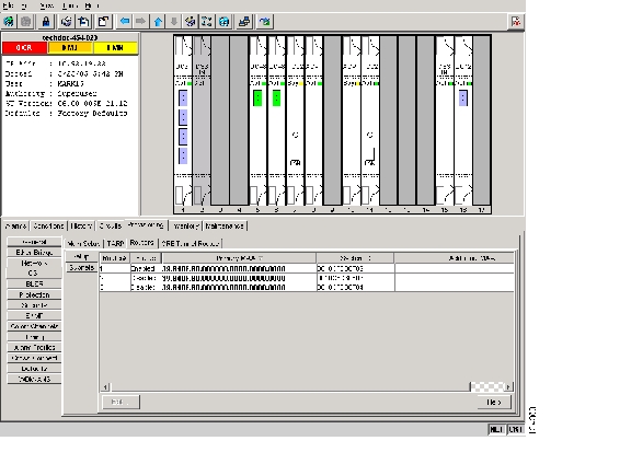
The ONS 15454 supports three OSI virtual routers. The routers are provisioned on the Provisioning > OSI > Routers tab, shown in Figure 13-26.
Figure 13-26 Provisioning OSI Routers
Each router has an editable manual area address and a unique NSAP System ID that is set to the node MAC address + n. For Router 1, n = 0. For Router 2, n = 1. For Router 3, n = 2. Each router can be enabled and connected to different OSI routing areas. However, Router 1 is the primary router, and it must be enabled before Router 2 and Router 3 can be enabled. The Router 1 manual area address and System ID create the NSAP address assigned to the node's TID. In addition, Router 1 supports OSI TARP, mediation, and tunneling functions that are not supported by Router 2 and Router 3. These include:
•
•
•
•
•
•
•
OSI virtual router constraints depend on the routing mode provisioned for the node. Table 13-16 shows the number of IS L1s, IS L1/L2s, and DCCs that are supported by each router. An IS Level1 and IS Level1/Level2 support one ES per DCC subnet and up to 100 ESs per LAN subnet.
Each OSI virtual router has a primary manual area address. You can also create two additional manual area addresses. These manual area addresses can be used to:
•
•
•
13.7.8 IP-over-CLNS Tunnels
IP-over-CLNS tunnels are used to encapsulate IP for transport across OSI NEs. The ONS 15454 supports two tunnel types:
•
•
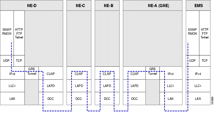
Figure 13-24 shows the protocol flow when an IP-over-CLNS tunnel is created through four NEs (A, B, C, and D). The tunnel ends are configured on NEs A and D, which support both IP and OSI. NEs B and C only support OSI, so they only route the OSI packets.
Figure 13-27 IP-over-CLNS Tunnel Flow
13.7.8.1 Provisioning IP-over-CLNS Tunnels
IP-over-CLNS tunnels must be carefully planned to prevent nodes from losing visibility or connectivity. Before you begin a tunnel, verify that the tunnel type, either Cisco IP or GRE, is supported by the equipment at the other end. Always verify IP and NSAP addresses. Provisioning of IP-over-CLNS tunnels in CTC is performed on the node view Provisioning > OSI > IP over CLNS Tunnels tab. For procedures, refer to the "Turn Up a Node" chapter in the Cisco ONS 15454 Procedure Guide.
Provisioning IP-over-CLNS tunnels on Cisco routers requires the following prerequisite tasks, as well as other OSI provisioning:
•
•
•
•
•
The Cisco IOS commands used to create IP-over-CLNS tunnels (CTunnels) are shown in Table 13-17.
If you are provisioning an IP-over-CLNS tunnel on a Cisco router, always follow procedures provided in the Cisco IOS documentation for the router you are provisioning. For information about ISO CLNS provisioning including IP-over-CLNS tunnels, see the "Configuring ISO CLNS" chapter in the Cisco IOS Apollo Domain, Banyon VINES, DECnet, ISO CLNS, and XNS Configuration Guide.
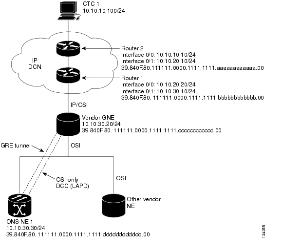
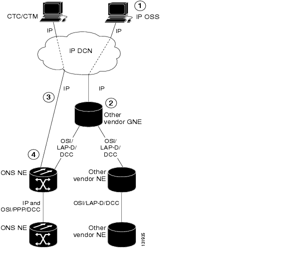
13.7.8.2 IP-over-CLNS Tunnel Scenario 1: ONS Node to Other Vendor GNE
Figure 13-28 shows an IP-over-CLNS tunnel created from an ONS node to another vendor GNE. The other vendor NE has an IP connection to an IP DCN to which a CTC computer is attached. An OSI-only (LAP-D) SDCC and a GRE tunnel are created between the ONS NE 1 to the other vender GNE.
ONS NE 1 IP-over-CLNS tunnel provisioning information:
•
•
•
•
•
Other vender GNE IP-over-CLNS tunnel provisioning information:
•
•
•
•
•
Figure 13-28 IP-over-CLNS Tunnel Scenario 1: ONS NE to Other Vender GNE
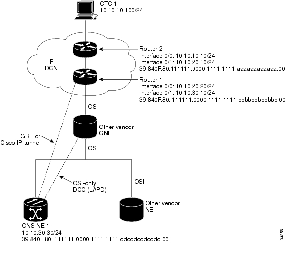
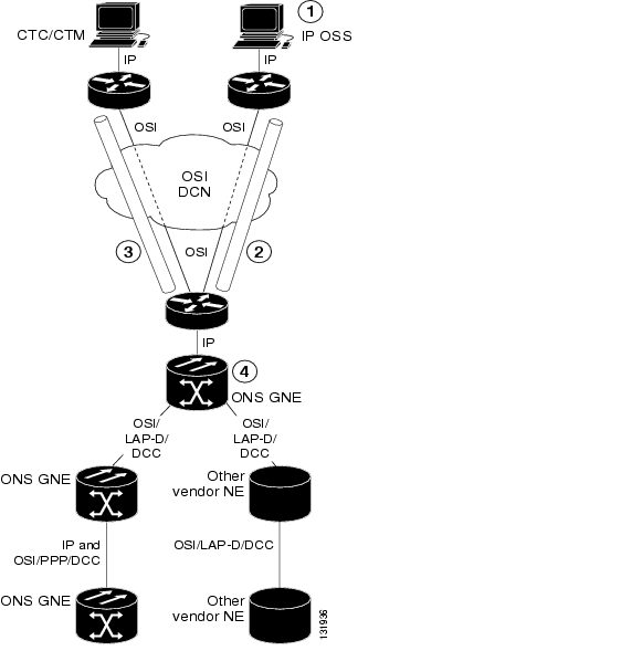
13.7.8.3 IP-over-CLNS Tunnel Scenario 2: ONS Node to Router
Figure 13-29 shows an IP-over-CLNS tunnel from an ONS node to a router. The other vendor NE has an OSI connection to a router on an IP DCN, to which a CTC computer is attached. An OSI-only (LAP-D) SDCC is created between the ONS NE 1 and the other vender GNE. The OSI over IP tunnel can be either the Cisco IP tunnel or a GRE tunnel, depending on the tunnel types supported by the router.
ONS NE 1 IP-over-CLNS tunnel provisioning:
•
•
•
•
•
Router 1 CTunnel (IP-over-CLNS) provisioning:
ip routing
clns routing
interface ctunnel 102
ip address 10.10.30.30 255.255.255.0
ctunnel destination 39.840F.80.1111.0000.1111.1111.dddddddddddd.00
interface Ethernet0/1
clns router isis
router isis
net 39.840F.80.1111.0000.1111.1111.bbbbbbbbbbbb.00
Figure 13-29 IP-over-CLNS Tunnel Scenario 2: ONS Node to Router
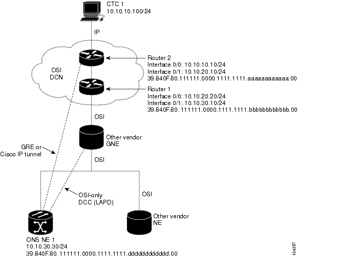
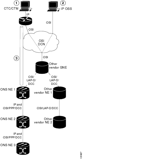
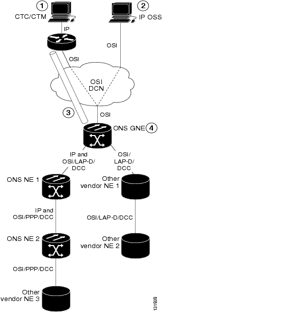
13.7.8.4 IP-over-CLNS Tunnel Scenario 3: ONS Node to Router Across an OSI DCN
Figure 13-30 shows an IP-over-CLNS tunnel from an ONS node to a router across an OSI DCN. The other vendor NE has an OSI connection to an IP DCN to which a CTC computer is attached. An OSI-only (LAP-D) SDCC is created between the ONS NE 1 and the other vender GNE. The OSI over IP tunnel can be either the Cisco IP tunnel or a GRE tunnel, depending on the tunnel types supported by the router.
ONS NE 1 IP-over-CLNS tunnel provisioning:
•
•
•
•
•
Router 2 IP-over-CLNS tunnel provisioning (sample Cisco IOS provisioning):
ip routing
clns routing
interface ctunnel 102
ip address 10.10.30.30 255.255.255.0
ctunnel destination 39.840F.80.1111.0000.1111.1111.dddddddddddd.00
interface Ethernet0/1
clns router isis
router isis
net 39.840F.80.1111.0000.1111.1111.aaaaaaaaaaaa.00
Figure 13-30 IP-over-CLNS Tunnel Scenario 3: ONS Node to Router Across an OSI DCN
13.7.9 OSI/IP Networking Scenarios
The following eight scenarios show examples of ONS 15454s in networks with OSI-based NEs. The scenarios show ONS 15454 nodes in a variety of roles. The scenarios assume the following:
•
•
•
•
•
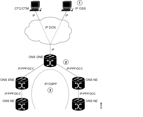
13.7.9.1 OSI/IP Scenario 1: IP OSS, IP DCN, ONS GNE, IP DCC, and ONS ENE
Figure 13-31 shows OSI/IP Scenario 1, the current ONS 15454 IP-based implementation, with an IP DCN, IP-over-PPP DCC, and OSPF routing.
Figure 13-31 OSI/IP Scenario 1: IP OSS, IP DCN, ONS GNE, IP DCC, and ONS ENE
IP OSS manages ONS 15454 using TL1 and FTP.
DCCs carry IP over the PPP protocol.
The ONS 15454 network is managed by IP over OSPF.
13.7.9.2 OSI/IP Scenario 2: IP OSS, IP DCN, ONS GNE, OSI DCC, and Other Vendor ENE
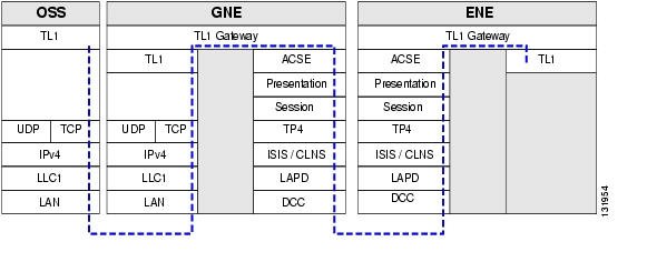
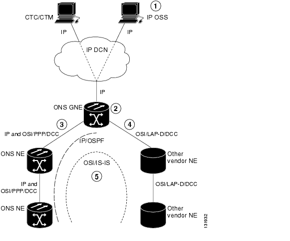
OSI/IP Scenario 2 ( Figure 13-32) shows an ONS 15454 GNE in a multivendor OSI network. Both the ONS 15454 GNE and the other vendor NEs are managed by an IP OSS using TL1 and FTP. The ONS 15454 is also managed by CTC and Cisco Transport Manager (CTM). Because the other vendor NE only supports TL1 and FTAM over the full OSI stack, the ONS 15454 GNE provides T-TD and FT-TD mediation to convert TL1/IP to TL1/OSI and FTAM/OSI to FTP/IP.
Figure 13-32 OSI/IP Scenario 2: IP OSS, IP DCN, ONS GNE, OSI DCC, and Other Vendor ENE
The ONS 15454 GNE routes TL1 traffic to the correct NE by resolving the TL1 TID to either an IP or NSAP address. For TL1 traffic to other vendor NEs (OSI-only nodes), the TID is resolved to an NSAP address. The ONS 15454 GNE passes the TL1 to the mediation function, which encapsulates it over the full OSI stack and routes it to the destination using the IS-IS protocol.
For TL1 traffic to ONS 15454 NEs, the TID is resolved to both an IP and an NSAP address. The ONS 15454 GNE follows the current TL1 processing model and forwards the request to the destination NE using the TCP/IP stack and OSPF routing.
OSS-initiated software downloads consist of two parts: the OSS to destination NE TL1 download request and the file transfer. The TL1 request is handled the same as described in the previous paragraph. The ONS 15454 NEs use FTP for file transfers. OSI-only NEs use FTAM to perform file transfers. The FTAM protocol is carried over OSI between the OSI NE and the ONS 15454 GNE. The GNE mediation translates between FTAM to FTP.
13.7.9.3 OSI/IP Scenario 3: IP OSS, IP DCN, Other Vendor GNE, OSI DCC, and ONS ENE
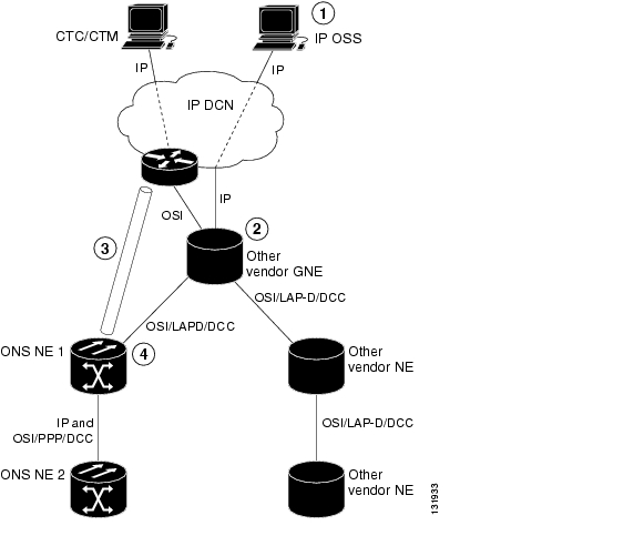
In OSI/IP Scenario 3 ( Figure 13-33), all TL1 traffic between the OSS and GNE is exchanged over the IP DCN. TL1 traffic targeted for the GNE is processed locally. All other TL1 traffic is forwarded to the OSI stack, which performs IP-to-OSI TL1 translation. The TL1 is encapsulated in the full OSI stack and sent to the target NE over the DCC. The GNE can route to any node within the IS-IS domain because all NEs, ONS 15454 and non-ONS 15454, have NSAP addresses and support IS-IS routing.
TL1 traffic received by an ONS 15454 NE and not addressed to its NSAP address is forwarded by IS-IS routing to the correct destination. TL1 traffic received by an ONS 15454 NE and addressed to its NSAP is sent up the OSI stack to the mediation function, which extracts the TL1 and passes it to the ONS 15454 TL1 processor.
An OSS initiated software download includes the OSS-to-destination node TL1 download request and the file transfer. The TL1 request is handled as described in the previous paragraph. The target node uses FTAM for file transfers because the GNE does not support IP on the DCC and cannot forward FTP. The ONS 15454 NEs therefore must support an FTAM client and initiate file transfer using FTAM when subtended to an OSI GNE.
In this scenario, the GNE has both IP and OSI DCN connections. The GNE only supports TL1 and FTP over IP. Both are translated and then carried over OSI to the destination ENE (ONS 15454 or OSI-only NE). All other IP traffic is discarded by the GNE. The CTC/CTM IP traffic is carried over an IP-over-OSI tunnel to an ONS 15454 NE. The tunnel is created between an external router and an ONS 15454 NE. The traffic is sent to the ONS 15454 terminating the tunnel. That ONS 15454 then forwards the traffic over the tunnel to CTC/CTM by way of the external router.
Figure 13-33 OSI/IP Scenario 3: IP OSS, IP DCN, Other Vendor GNE, OSI DCC, and ONS ENE
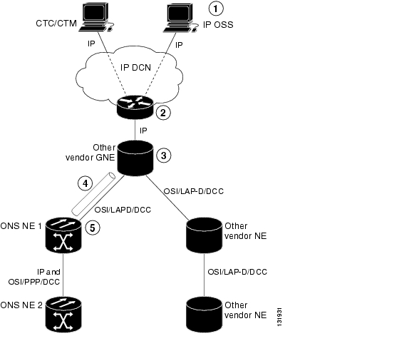
Figure 13-34 shows the same scenario, except the IP-over-CLNS tunnel endpoint is the GNE rather than the DCN router.
Figure 13-34 OSI/IP Scenario 3 with OSI/IP-over-CLNS Tunnel Endpoint at the GNE
13.7.9.4 OSI/IP Scenario 4: Multiple ONS DCC Areas
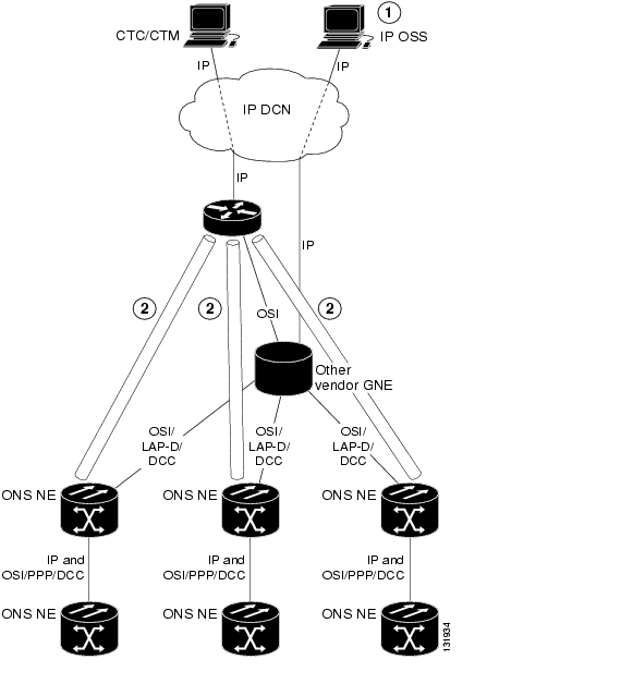
OSI/IP Scenario 4 ( Figure 13-35) is similar to OSI/IP Scenario 3 except that the OSI GNE is subtended by multiple isolated ONS 15454 areas. A separate IP-over-CLNS tunnel is required to each isolated ONS 15454 OSPF area. An alternate approach is to create a single IP-over-CLNS tunnel from CTC/CTM to an ONS 15454 NE, and then to configure a tunnel from that NE to an NE in each isolated OSPF area. This approach requires additional static routes.
Figure 13-35 OSI/IP Scenario 4: Multiple ONS DCC Areas
The IP OSS manages ONS 15454 and other vendor NEs using TL1 and FTP.
A separate tunnel is created for each isolated ONS 15454 DCC area.
13.7.9.5 OSI/IP Scenario 5: GNE Without an OSI DCC Connection
OSI/IP Scenario 5 ( Figure 13-36) is similar to OSI/IP Scenario 3 except that the OSI GNE only has an IP connection to the DCN. It does not have an OSI DCN connection to carry CTC/CTM IP traffic through an IP-over-OSI tunnel. A separate DCN to ONS 15454 NE connection is created to provide CTC/CTM access.
Figure 13-36 OSI/IP Scenario 5: GNE Without an OSI DCC Connection
13.7.9.6 OSI/IP Scenario 6: IP OSS, OSI DCN, ONS GNE, OSI DCC, and Other Vendor ENE
OSI/IP Scenario 6 ( Figure 13-37) shows how the ONS 15454 supports OSI DCNs. The OSI DCN has no impact on the ONS 15454 because all IP traffic (CTC/CTM, FTP, and TL1) is tunneled through the OSI DCN.
Figure 13-37 OSI/IP Scenario 6: IP OSS, OSI DCN, ONS GNE, OSI DCC, and Other Vendor ENE
13.7.9.7 OSI/IP Scenario 7: OSI OSS, OSI DCN, Other Vender GNE, OSI DCC, and ONS NEs
OSI/IP Scenario 7 ( Figure 13-38) shows an example of a European network.
Figure 13-38 OSI/IP Scenario 7: OSI OSS, OSI DCN, Other Vender GNE, OSI DCC, and ONS NEs
In European networks:
•
•
•
•
•
Management traffic between CTC/CTM and ONS 15454 NEs is carried over an IP-over-CLNS tunnel. A static route is configured on the ONS 15454 that terminates the tunnel (ONS 15454 NE 1) so that downstream ONS 15454 NEs (ONS 15454 NE 2 and 3) know how to reach CTC/CTM.
13.7.9.8 OSI/IP Scenario 8: OSI OSS, OSI DCN, ONS GNE, OSI DCC, and Other Vender NEs
OSI/IP Scenario 8 ( Figure 13-39) is another example of a European network. Similar to OSI/IP Scenario 7, the ONS 15454 NEs are solely managed by CTC/CTM. The CTC/CTM IP traffic is carried over a IP-over-OSI tunnel between an external router and the ONS 15454 GNE. The GNE extracts the IP from the tunnel and forwards it to the destination ONS 15454. Management traffic between the OSS and other vendor NEs is routed by the ONS 15454 GNE and NEs. This is possible because all ONS 15454 NEs run dual stacks (OSI and IP).
Figure 13-39 OSI/IP Scenario 8: OSI OSS, OSI DCN, ONS GNE, OSI DCC, and Other Vender NEs
13.7.10 Provisioning OSI in CTC
Table 13-18 shows the OSI actions that are performed from the node view Provisioning tab. Refer to the Cisco ONS 15454 Procedure Guide for OSI procedures and tasks.
Table 13-19 shows the OSI actions that are performed from the node view Maintenance tab.
![]()
![]()
![]()
![]()
![]()
![]()
![]()
![]()
Posted: Thu Oct 25 03:40:36 PDT 2007
All contents are Copyright © 1992--2007 Cisco Systems, Inc. All rights reserved.
Important Notices and Privacy Statement.