|
|

Table Of Contents
11.2.1 Concatenated STS Time Slot Assignments
11.2.4 Circuit Protection Types
11.2.5 Circuit Information in the Edit Circuit Window
11.3 Cross-Connect Card Bandwidth
11.5.1 Traditional DCC Tunnels
11.5.2 IP-Encapsulated Tunnels
11.6 Multiple Destinations for Unidirectional Circuits
11.8.1 Open-Ended Path Protection Circuits
11.8.2 Go-and-Return Path Protection Routing
11.9 BLSR Protection Channel Access Circuits
11.10 BLSR STS and VT Squelch Tables
11.10.1 BLSR STS Squelch Table
11.12 Path Signal Label, C2 Byte
11.13 Automatic Circuit Routing
11.13.1 Bandwidth Allocation and Routing
11.13.2 Secondary Sources and Destinations
11.15 Constraint-Based Circuit Routing
11.16 Virtual Concatenated Circuits
11.16.3 Link Capacity Adjustment
11.17.4 Two Circuit Bridge and Roll
Circuits and Tunnels
Note
The terms "Unidirectional Path Switched Ring" and "UPSR" may appear in Cisco literature. These terms do not refer to using Cisco ONS 15xxx products in a unidirectional path switched ring configuration. Rather, these terms, as well as "Path Protected Mesh Network" and "PPMN," refer generally to Cisco's path protection feature, which may be used in any topological network configuration. Cisco does not recommend using its path protection feature in any particular topological network configuration.
This chapter explains Cisco ONS 15454 synchronous transport signal (STS), virtual tributary (VT), and virtual concatenated (VCAT) circuits and VT, data communications channel (DCC), and IP-encapsulated tunnels. To provision circuits and tunnels, refer to the Cisco ONS 15454 Procedure Guide.
Chapter topics include:
•
•
•
•
•
•
•
11.1 Overview
You can create circuits across and within ONS 15454 nodes and assign different attributes to circuits. For example, you can:
•
•
•
•
•
•
•
•
•
You can provision circuits at either of the following points:
•
•
•
11.2 Circuit Properties
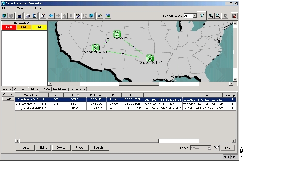
The ONS 15454 Cisco Transport Controller (CTC) Circuits window, which appears in network, node, and card view, is where you can view information about circuits. The Circuits window ( Figure 11-1) provides the following information:
•
•
•
•
•
•
•
•
•
•
•
•
•
The Filter button allows you to filter the circuits in network, node, or card view based on circuit name, size, type, direction, and other attributes. In addition, you can export the Circuit window data in HTML, comma-separated values (CSV), or tab-separated values (TSV) format using the Export command from the File menu.
Figure 11-1 ONS 15454 Circuit Window in Network View
11.2.1 Concatenated STS Time Slot Assignments
Table 11-1 shows the available time slot assignments for concatenated STSs when using CTC to provision circuits.
11.2.2 Circuit Status
The circuit statuses that appear in the Circuit window Status column are generated by CTC based on conditions along the circuit path. Table 11-2 shows the statuses that can appear in the Status column.
Table 11-2 ONS 15454 Circuit Status
CREATING
CTC is creating a circuit.
DISCOVERED
CTC created a circuit. All components are in place and a complete path exists from circuit source to destination.
DELETING
CTC is deleting a circuit.
PARTIAL
A CTC-created circuit is missing a cross-connect or network span, a complete path from source to destinations does not exist, or an alarm interface panel (AIP) change occurred on one of the circuit nodes and the circuit is in need of repair. (AIPs store the node MAC address.)
In CTC, circuits are represented using cross-connects and network spans. If a network span is missing from a circuit, the circuit status is PARTIAL. However, a PARTIAL status does not necessarily mean a circuit traffic failure has occurred, because traffic might flow on a protect path.
Network spans are in one of two states: up or down. On CTC circuit and network maps, up spans appear as green lines, and down spans appear as gray lines. If a failure occurs on a network span during a CTC session, the span remains on the network map but its color changes to gray to indicate that the span is down. If you restart your CTC session while the failure is active, the new CTC session cannot discover the span and its span line does not appear on the network map.
Subsequently, circuits routed on a network span that goes down appear as DISCOVERED during the current CTC session, but appear as PARTIAL to users who log in after the span failure.
DISCOVERED_TL1
A TL1-created circuit or a TL1-like, CTC-created circuit is complete. A complete path from source to destinations exists.
PARTIAL_TL1
A TL1-created circuit or a TL1-like, CTC-created circuit is missing a cross-connect or circuit span (network link), and a complete path from source to destinations does not exist.
CONVERSION_PENDING
An existing circuit in a topology upgrade is set to this state. The circuit returns to the DISCOVERED state once the topology upgrade is complete. For more information about topology upgrades, see Chapter 12, "SONET Topologies and Upgrades."
PENDING_MERGE
Any new circuits created to represent an alternate path in a topology upgrade are set to this status to indicate that it is a temporary circuit. These circuits can be deleted if a topology upgrade fails. For more information about topology upgrades, see Chapter 12, "SONET Topologies and Upgrades."
DROP_PENDING
A circuit is set to this status when a new circuit drop is being added.
ROLL_PENDING
A circuit roll is awaiting completion or cancellation.
11.2.3 Circuit States
The circuit service state is an aggregate of the cross-connect states within the circuit.
•
•
•
You can assign a state to circuit cross-connects at two points:
•
•
Note
During circuit creation, you can apply a service state to the drop ports in a circuit; however, CTC does not apply a requested state other than IS-NR to drop ports if:
•
•
•
•
Circuits do not use the soak timer, but ports do. The soak period is the amount of time that the port remains in the OOS-AU,AINS service state after a signal is continuously received. When the cross-connects in a circuit are in the OOS-AU,AINS service state, the ONS 15454 monitors the cross-connects for an error-free signal. It changes the state of the circuit from OOS to IS or to OOS-PARTIAL as each cross-connect assigned to the circuit path is completed. This allows you to provision a circuit using TL1, verify its path continuity, and prepare the port to go into service when it receives an error-free signal for the time specified in the port soak timer. Two common examples of state changes you see when provisioning circuits using CTC are:
•
•
To find the remaining port soak time, choose the Maintenance > AINS Soak tabs in card view and click the Retrieve button. If the port is in the OOS-AU,AINS state and has a good signal, the Time Until IS column shows the soak count down status. If the port is OOS-AU,AINS and has a bad signal, the Time Until IS column indicates that the signal is bad. You must click the Retrieve button to obtain the latest time value.
For more information about port and cross-connect states, see "Administrative and Service States."
11.2.4 Circuit Protection Types
The Protection column in the Circuit window shows the card (line) and SONET topology (path) protection used for the entire circuit path. Table 11-3 shows the protection type indicators that appear in this column.
11.2.5 Circuit Information in the Edit Circuit Window
You can edit a selected circuit using the Edit button on the Circuits window. The tabs that appear depend on the circuit chosen:
•
•
•
•
•
•
•
Using the Export command from the File menu, you can export data from the UPSR Selectors, UPSR Switch Counts, State, and Merge tabs in HTML, comma-separated values (CSV), or tab-separated values (TSV) format.
The Show Detailed Map checkbox in the Edit Circuit window updates the graphical view of the circuit to show more detailed routing information, such as:
•
•
•
•
•
•
For BLSRs, the detailed map shows the number of BLSR fibers and the BLSR ring ID. For path protection configurations, the map shows the active and standby paths from circuit source to destination, and it also shows the working and protect paths. Selectors appear as pentagons on the detailed circuit map. The map indicates nodes set up as DRI nodes. For VCAT circuits, the detailed map is not available for an entire VCAT circuit. However, you can view the detailed map to see the circuit route for each individual member.
You can also view alarms and states on the circuit map, including:
•
•
•
•
•
•
•
By default, the working path is indicated by a green, bidirectional arrow, and the protect path is indicated by a purple, bidirectional arrow. Source and destination ports are shown as circles with an S and D. Port states are indicated by colors, shown in Table 11-4.
Table 11-4 Port State Color Indicators
Green
IS-NR
Gray
OOS-MA,DSBLD
Violet
OOS-AU,AINS
Blue (Cyan)
OOS-MA,MT
In detailed view, a notation within or by the squares or selector pentagons indicates switches and loopbacks, including:
•
•
•
•
Move the mouse cursor over nodes, ports, and spans to see tooltips with information including the number of alarms on a node (organized by severity), the port service state, and the protection topology.
Right-click a node, port, or span on the detailed circuit map to initiate certain circuit actions:
•
•
•
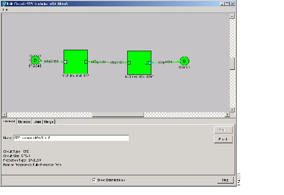
Figure 11-2 shows a circuit routed on a two-fiber BLSR. A port is shown in terminal loopback.
Figure 11-2 BLSR Circuit Displayed on the Detailed Circuit Map
11.3 Cross-Connect Card Bandwidth
The ONS 15454 XCVT, XC10G, and XC-VXC-10G cross-connect cards perform port-to-port, time-division multiplexing (TDM). XCVT, XC10G, and XC-VXC-10G cards perform STS, VT2 (XC-VXC-10G only), and VT1.5 multiplexing.
The STS matrix on the XCVT cross-connect card has a capacity for 288 STS terminations, and the XC10G and XC-VXC-10G cards each have a capacity for 1152 STS terminations. Because each STS circuit requires a minimum of two terminations, one for ingress and one for egress, the XCVT card has a capacity for 144 STS circuits, while the XC10G and XC-VXC-10G cards have a capacity for 576 STS circuits. However, this capacity is reduced at path protection and 1+1 nodes because three STS terminations are required at circuit source and destination nodes and four terminations are required at 1+1 circuit pass-through nodes. path protection pass-through nodes only require two STS terminations.
The XCVT and XC10G cards perform VT1.5 multiplexing through 24 logical STS ports on the XCVT or XC10G VT matrix, and the XC-VXC-10G card performs VT1.5 and VT2 multiplexing through 96 logical STS ports on the XC-VXC-10G VT matrix. Each logical STS port can carry 28 VT1.5s or 21 VT2s. Subsequently, the VT matrix on the XCVT or XC10G has capacity for 672 VT1.5 terminations, or 336 VT1.5 circuits. The VT matrix on the XC-VXC-10G has capacity for 2688 VT1.5 terminations (1344 VT1.5 bidirectional circuits) or 2016 VT2 terminations (1008 VT2 bidirectional circuits). Every circuit requires two terminations, one for ingress and one for egress. However, this capacity is only achievable if:
•
•
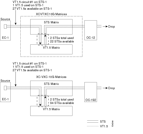
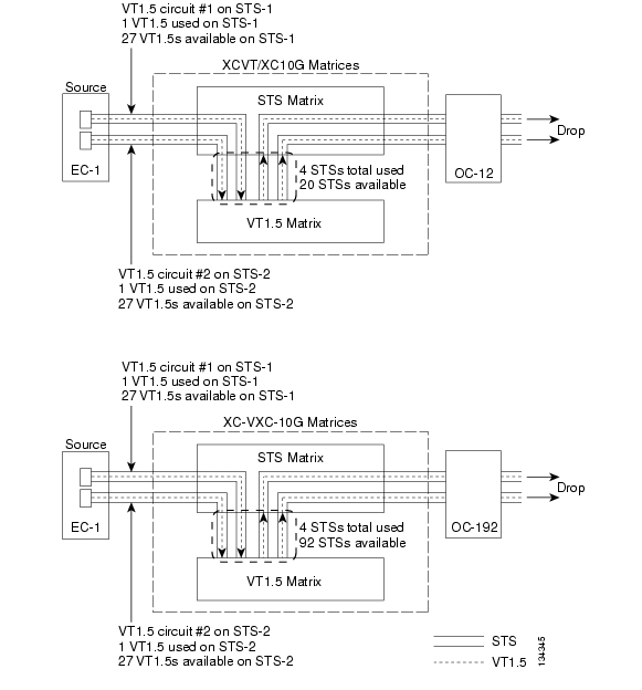
For example, if you create a VT1.5 circuit from an STS-1 on a drop card, two VT matrix STS ports are used, as shown in Figure 11-3. If you create a second VT1.5 circuit from the same STS port on the drop card, no additional logical STS ports are used on the VT matrix. In fact, you can create up to 28 VT1.5 circuits using the same STS-1 port. However, if the next VT1.5 circuit originates on a different STS, an additional pair of STS ports on the VT matrix is used, as shown in Figure 11-4. If you continued to create VT1.5 circuits on different EC-1 STSs and mapped each to an unused outbound STS, the VT matrix capacity would be reached after you created 12 VT1.5 circuits in the case of the XCVT or XC10G cards, or 48 VT1.5 circuits in the case of the XC-VXC-10G card.
Figure 11-3 One VT1.5 Circuit on One STS
Figure 11-4 Two VT1.5 Circuits in a BLSR
Note
VT matrix capacity is also affected by SONET protection topology and node position within the circuit path. Matrix usage is slightly higher for path protection nodes than BLSR and 1+1 nodes. Circuits use two VT matrix ports at pass-through nodes if VT tunnels and aggregation points are not used. If the circuit is routed on a VT tunnel or an aggregation point, no VT matrix resources are used. Table 11-5 shows basic STS port usage rates for VT 1.5 circuits.
Cross-connect card resources can be viewed on the Maintenance > Cross-Connect > Resource Usage tab. This tab shows:
•
•
•
To maximize resources on the cross-connect card VT matrix, keep the following points in mind as you provision circuits:
•
•
•
11.4 Portless Transmux
The DS3XM-12 card provides a portless transmux interface to change DS-3s into VT1.5s. For XCVT drop slots, the DS3XM-12 card provides a maximum of 6 portless transmux interfaces; for XCVT trunk slots and XC10G or XC-VXC-10G slots, the DS3XM-12 card provides a maximum of 12 portless transmux interfaces. If two ports are configured as portless transmux, CTC allows you to create a DS3/STS1 circuit using one of these ports as the circuit end point. You can create separate DS1/VT1.5 circuits (up to 28) using the other port in this portless transmux pair.
When creating a circuit through the DS3XM-12 card, the portless pair blocks the mapped physical port(s); CTC does not display a blocked physical port in the source or destination drop-down list during circuit creation. Table 11-6 lists the portless transmux mapping for XCVT drop ports.
Table 11-6 Portless Transmux Mapping for XCVT Drop Ports
1, 2
13, 14
3, 4
15, 16
5, 6
17, 18
7, 8
19, 20
9, 10
21, 22
11, 12
23, 24
Table 11-7 lists the portless transmux for XCVT trunk ports and for XC10G or XC-VXC-10G any-slot ports.
11.5 DCC Tunnels
SONET provides four DCCs for network element (NE) operation, administration, maintenance, and provisioning (OAM&P): one on the SONET Section layer (DCC1) and three on the SONET Line layer (DCC2, DCC3, and DCC4). The ONS 15454 uses the Section DCC (SDCC) for ONS 15454 management and provisioning. An SDCC and Line DCC (LDCC) each provide 192 Kbps of bandwidth per channel. The aggregate bandwidth of the three LDCCs is 576 Kbps. When multiple DCC channels exist between two neighboring nodes, the ONS 15454 balances traffic over the existing DCC channels using a load balancing algorithm. This algorithm chooses a DCC for packet transport by considering packet size and DCC utilization. You can tunnel third-party SONET equipment across ONS 15454 networks using one of two tunneling methods: a traditional DCC tunnel or an IP-encapsulated tunnel.
11.5.1 Traditional DCC Tunnels
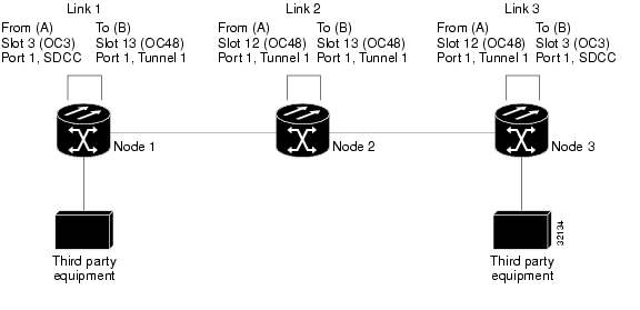
In traditional DCC tunnels, you can use the three LDCCs and the SDCC (when not used for ONS 15454 DCC terminations). A traditional DCC tunnel endpoint is defined by slot, port, and DCC, where DCC can be either the SDCC or one of the LDCCs. You can link LDCCs to LDCCs and link SDCCs to SDCCs. You can also link an SDCC to an LDCC, and an LDCC to an SDCC. To create a DCC tunnel, you connect the tunnel endpoints from one ONS 15454 optical port to another. Cisco recommends a maximum of 84 DCC tunnel connections for an ONS 15454. Table 11-8 shows the DCC tunnels that you can create using different OC-N cards.
Figure 11-5 shows a DCC tunnel example. Third-party equipment is connected to OC-3 cards at Node 1/Slot 3/Port 1 and Node 3/Slot 3/Port 1. Each ONS 15454 node is connected by OC-48 trunk (span) cards. In the example, three tunnel connections are created, one at Node 1 (OC-3 to OC-48), one at Node 2 (OC-48 to OC-48), and one at Node 3 (OC-48 to OC-3).
Figure 11-5 Traditional DCC Tunnel
When you create DCC tunnels, keep the following guidelines in mind:
•
•
•
•
•
11.5.2 IP-Encapsulated Tunnels
An IP-encapsulated tunnel puts an SDCC in an IP packet at a source node and dynamically routes the packet to a destination node. To compare traditional DCC tunnels with IP-encapsulated tunnels, a traditional DCC tunnel is configured as one dedicated path across a network and does not provide a failure recovery mechanism if the path is down. An IP-encapsulated tunnel is a virtual path, which adds protection when traffic travels between different networks.
IP-encapsulated tunneling has the potential of flooding the DCC network with traffic resulting in a degradation of performance for CTC. The data originating from an IP tunnel can be throttled to a user-specified rate, which is a percentage of the total SDCC bandwidth.
Each ONS 15454 supports up to ten IP-encapsulated tunnels. You can convert a traditional DCC tunnel to an IP-encapsulated tunnel or an IP-encapsulated tunnel to a traditional DCC tunnel. Only tunnels in the DISCOVERED status can be converted.
Caution
11.6 Multiple Destinations for Unidirectional Circuits
Unidirectional circuits can have multiple destinations for use in broadcast circuit schemes. In broadcast scenarios, one source transmits traffic to multiple destinations, but traffic is not returned to the source.
When you create a unidirectional circuit, the card that does not have its backplane receive (Rx) input terminated with a valid input signal generates a loss of signal (LOS) alarm. To mask the alarm, create an alarm profile suppressing the LOS alarm and apply the profile to the port that does not have its Rx input terminated.
11.7 Monitor Circuits
Monitor circuits are secondary circuits that monitor traffic on primary bidirectional circuits. Figure 11-6 shows an example of a monitor circuit. At Node 1, a VT1.5 is dropped from Port 1 of an EC1-12 card. To monitor the VT1.5 traffic, plug test equipment into Port 2 of the EC1-12 card and provision a monitor circuit to Port 2. Circuit monitors are one-way. The monitor circuit in Figure 11-6 monitors VT1.5 traffic received by Port 1 of the EC1-12 card.
Figure 11-6 VT1.5 Monitor Circuit Received at an EC1-12 Port
Note
11.8 Path Protection Circuits
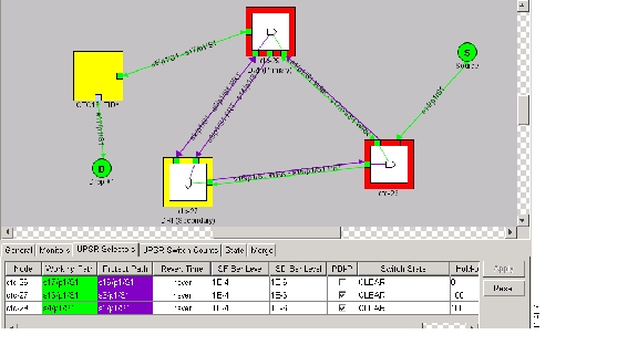
Use the Edit Circuits window to change path protection selectors and switch protection paths ( Figure 11-7). In the UPSR Selectors subtab in the Edit Circuits window, you can:
•
•
•
•
•
Note
In the UPSR Switch Counts subtab, you can:
•
•
Figure 11-7 Editing Path Protection Selectors
11.8.1 Open-Ended Path Protection Circuits
If ONS 15454s are connected to a third-party network, you can create an open-ended path protection circuit to route a circuit through it. To do this, you create four circuits. One circuit is created on the source ONS 15454 network. This circuit has one source and two destinations, each destination provisioned to the ONS 15454 interface that is connected to the third-party network. The second and third circuits are created on the third-party network so that the circuit travels across the network on two diverse paths to the far end ONS 15454. At the destination node, the fourth circuit is created with two sources, one at each node interface connected to the third-party network. A selector at the destination node chooses between the two signals that arrive at the node, similar to a regular path protection circuit.
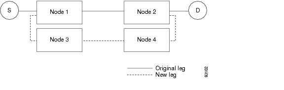
11.8.2 Go-and-Return Path Protection Routing
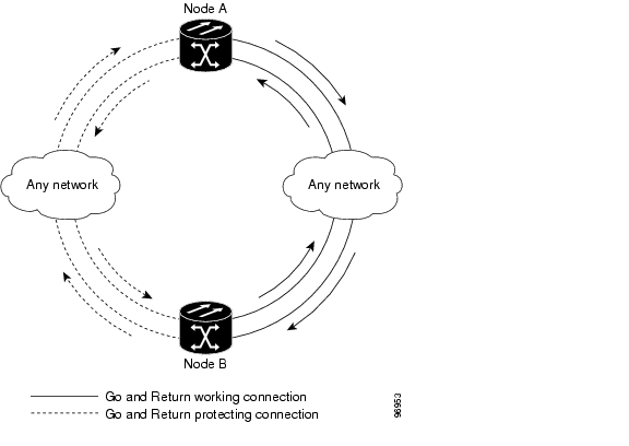
The go-and-return path protection routing option allows you to route the path protection working path on one fiber pair and the protect path on a separate fiber pair ( Figure 11-8). The working path will always be the shortest path. If a fault occurs, both the working and protection fibers are not affected. This feature only applies to bidirectional path protection circuits. The go-and-return option appears in the Circuit Attributes panel of the Circuit Creation wizard.
Figure 11-8 Path Protection Go-and-Return Routing
11.9 BLSR Protection Channel Access Circuits
You can provision circuits to carry traffic on BLSR protection channels when conditions are fault-free. Traffic routed on BLSR PCA circuits, called extra traffic, has lower priority than the traffic on the working channels and has no means for protection. During ring or span switches, PCA circuits are preempted and squelched. For example, in a two-fiber OC-48 BLSR, STSs 25 to 48 can carry extra traffic when no ring switches are active, but PCA circuits on these STSs are preempted when a ring switch occurs. When the conditions that caused the ring switch are remedied and the ring switch is removed, PCA circuits are restored. If the BLSR is provisioned as revertive, this occurs automatically after the fault conditions are cleared and the reversion timer has expired.
Traffic provisioning on BLSR protection channels is performed during circuit provisioning. The Protection Channel Access check box appears whenever Fully Protected Path is unchecked in the circuit creation wizard. Refer to the Cisco ONS 15454 Procedure Guide for more information. When provisioning PCA circuits, two considerations are important to keep in mind:
•
•
11.10 BLSR STS and VT Squelch Tables
ONS 15454 nodes display STS and VT squelch tables depending on the type of circuits created. For example, if a fiber cut occurs, the BLSR squelch tables show STSs or VTs that will be squelched for every isolated node. Squelching replaces traffic by inserting the appropriate alarm indication signal path (AIS-P) and prevents traffic misconnections. For an STS with a VT-access check mark, the AIS-P will be removed after 100 ms. To view the squelch tables, refer to the "Manage Circuits" chapter in the Cisco ONS 15454 Procedure Guide for detailed instructions. For more information about BLSR squelching, refer to Telcordia GR-1230.
11.10.1 BLSR STS Squelch Table
BLSR STS squelch tables show STSs that will be squelched for every isolated node.
The BLSR Squelch Table window displays the following information:
•
•
•
•
•
•
•
•
•
Note
11.10.2 BLSR VT Squelch Table
BLSR VT squelch tables only appear on the node dropping VTs from a BLSR and are used to perform VT-level squelching when a node is isolated. VT squelching is supported on the ONS 15454 and the ONS 15327 platforms. The ONS 15600 platform does not support VT squelching; however, when an ONS 15454 and an ONS 15600 are in the same network, the ONS 15600 node allows the ONS 15454 node to carry VT circuits in a VT tunnel. The ONS 15600 performs 100-ms STS-level squelching for each VT-access STS at the switching node in case of a node failure.
When using a VT circuit on a VT tunnel (VTT), the VTT allows multiple VT circuits to be passed through on a single STS without consuming VT matrix resources on the cross-connect card. Both endpoints of the VTT are the source and destination nodes for the VTT. The node carrying VT circuits through a VTT is called a VT-access node. In case of a source and destination node failure of the VTT, the switching node performs 100-ms STS-level squelching for the VTT STS. The node dropping VT traffic performs VT-level squelching. VT traffic on the VTT that is not coming from the failed node is protected.
When using a VT circuit on a VT aggregation point (VAP), the VAP allows multiple VT circuits to be aggregated into a single STS without consuming VT matrix resources on the cross-connect card. The source for each VAP STS timeslot is the STS-grooming end where VT1.5 circuits are aggregated into a single STS. The destination for each VAP STS is the VT-grooming end where VT1.5 circuits originated. The source node for each VT circuit on a VAP is the STS-grooming end where the VT1.5 circuits are aggregated into a single STS. The STS grooming node is not a VT-access node. The non VT-access node performs STS-level squelching for each STS timeslot at the switching node in case the VT-grooming node fails. The node dropping VT traffic performs VT-level squelching for each VT timeslot in case the STS-grooming end node fails. No VT traffic on the VAP is protected during a failure of the STS-grooming node or the VT-grooming node.
To view the VT squelch table, double-click the VT with a check mark in the BLSR STS squelch table window. The check mark appears on every VT-access STS; however, the VT-squelch table appears only by double-clicking the check mark on the node dropping the VT. The intermediate node of the VT does not maintain the VT-squelch table.
The VT squelch table provides the following information:
•
•
•
11.11 Section and Path Trace
SONET J0 section and J1 and J2 path trace are repeated, fixed-length strings composed of 16 or 64 consecutive bytes. You can use the strings to monitor interruptions or changes to circuit traffic.
The OC192-XFP and MRC-12 cards support J0 section trace. Table 11-9 shows the ONS 15454 cards that support J1 path trace. DS-1 and DS-3 cards can transmit and receive the J1 field, while the EC-1, OC-3, OC-48 AS, and OC-192 can only receive the J1 bytes. Cards that are not listed in the table do not support the J1 byte. The DS3XM-12 card supports J2 path trace for VT circuits.
Table 11-9 ONS 15454 Cards Capable of J1 Path Trace
Transmit and Receive
CE-Series
DS1-141
DS1N-14
DS1/EC1-56
DS3-12E
DS3i-N-12
DS3/EC1-48
DS3N-12E
DS3XM-6
DS3XM-12
FC_MR-4
G-Series
ML-Series
Receive Only
EC1-12
OC3 IR 4/STM1 SH 1310
OC3 IR 4/STM1 SH 1310-8
OC12/STM4-4
OC48 IR/STM16 SH AS 1310
OC48 LR/STM16 LH AS 1550
OC192 SR/STM64 IO 1310
OC192 LR/STM64 LH 1550
OC192 IR/STM SH 1550
OC192-XFP
1 J1 path trace is not supported for DS-1s used in VT circuits.
If the string received at a circuit drop port does not match the string the port expects to receive, an alarm is raised. Two path trace modes are available:
•
•
11.12 Path Signal Label, C2 Byte
One of the overhead bytes in the SONET frame is the C2 byte. The SONET standard defines the C2 byte as the path signal label. The purpose of this byte is to communicate the payload type being encapsulated by the STS path overhead (POH). The C2 byte functions similarly to EtherType and Logical Link Control (LLC)/Subnetwork Access Protocol (SNAP) header fields on an Ethernet network; it allows a single interface to transport multiple payload types simultaneously. C2 byte hex values are provided in Table 11-10.
If a circuit is provisioned using a terminating card, the terminating card provides the C2 byte. A VT circuit is terminated at the XCVT, XC10G, or XC-VXC-10G card, which generates the C2 byte (0x02) downstream to the STS terminating cards. The XCVT, XC10G, or XC-VXC-10G card generates the C2 value (0x02) to the DS1 or DS3XM terminating card. If an optical circuit is created with no terminating cards, the test equipment must supply the path overhead in terminating mode. If the test equipment is in pass-through mode, the C2 values usually change rapidly between 0x00 and 0xFF. Adding a terminating card to an optical circuit usually fixes a circuit having C2 byte problems. Table 11-11 lists label assignments for signals with payload defects.
11.13 Automatic Circuit Routing
If you select automatic routing during circuit creation, CTC routes the circuit by dividing the entire circuit route into segments based on protection domains. For unprotected segments of circuits provisioned as fully protected, CTC finds an alternate route to protect the segment, creating a virtual path protection. Each segment of a circuit path is a separate protection domain. Each protection domain is protected in a specific protection scheme including card protection (1+1, 1:1, etc.) or SONET topology (path protection, BLSR, etc.).
The following list provides principles and characteristics of automatic circuit routing:
•
•
•
•
•
•
•
11.13.1 Bandwidth Allocation and Routing
Within a given network, CTC routes circuits on the shortest possible path between source and destination based on the circuit attributes, such as protection and type. CTC considers using a link for the circuit only if the link meets the following requirements:
•
•
•
If CTC cannot find a link that meets these requirements, an error appears.
The same logic applies to VT circuits on VT tunnels. Circuit routing typically favors VT tunnels because VT tunnels are shortcuts between a given source and destination. If the VT tunnel in the route is full (no more bandwidth), CTC asks whether you want to create an additional VT tunnel.
11.13.2 Secondary Sources and Destinations
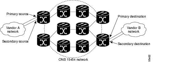
CTC supports secondary circuit sources and destinations (drops). Secondary sources and destinations typically interconnect two third-party networks, as shown in Figure 11-9. Traffic is protected while it goes through a network of ONS 15454s.
Figure 11-9 Secondary Sources and Destinations
Several rules apply to secondary sources and destinations:
•
•
•
•
For bidirectional circuits, CTC creates a path protection connection at the source node that allows traffic to be selected from one of the two sources on the ONS 15454 network. If you check the Fully Path Protected option during circuit creation, traffic is protected within the ONS 15454 network. At the destination, another path protection connection is created to bridge traffic from the ONS 15454 network to the two destinations. A similar but opposite path exists for the reverse traffic flowing from the destinations to the sources.
For unidirectional circuits, a path protection drop-and-continue connection is created at the source node.
11.14 Manual Circuit Routing
Routing circuits manually allows you to:
•
•
•
•
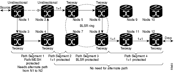
CTC imposes the following rules on manual routes:
•
•
Figure 11-10 Alternate Paths for Virtual Path Protection Segments
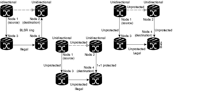
•
•
Figure 11-11 Mixing 1+1 or BLSR Protected Links With a Path Protection
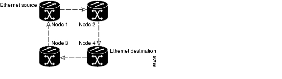
•
Figure 11-12 Ethernet Shared Packet Ring Routing
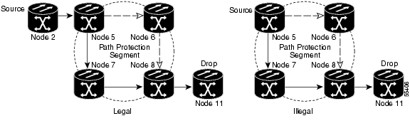
•
Figure 11-13 Ethernet and Path Protection
•
If you provision full path protection, CTC verifies that the route selection is protected at all segments. A route can have multiple protection domains with each domain protected by a different scheme.
Table 11-12 through Table 11-15 summarize the available node connections. Any other combination is invalid and generates an error.
Although virtual path protection segments are possible in VT tunnels, VT tunnels are still considered unprotected. If you need to protect VT circuits, use two independent VT tunnels that are diversely routed or use a VT tunnel that is routed over 1+1, BLSR, or a mixture of 1+1 and BLSR links.
11.15 Constraint-Based Circuit Routing
When you create circuits, you can choose Fully Protected Path to protect the circuit from source to destination. The protection mechanism used depends on the path that CTC calculates for the circuit. If the network is composed entirely of BLSR or 1+1 links, or the path between source and destination can be entirely protected using 1+1 or BLSR links, no path-protected mesh network (PPMN), or virtual path protection, protection is used.
If PPMN protection is needed to protect the path, set the level of node diversity for the PPMN portions of the complete path in the Circuit Routing Preferences area of the Circuit Creation dialog box:
•
•
•
When you choose automatic circuit routing during circuit creation, you have the option to require or exclude nodes and links in the calculated route. You can use this option to achieve the following results:
•
•
CTC considers required nodes and links to be an ordered set of elements. CTC treats the source nodes of every required link as required nodes. When CTC calculates the path, it makes sure that the computed path traverses the required set of nodes and links and does not traverse excluded nodes and links.
The required nodes and links constraint is only used during the primary path computation and only for PPMN domains/segments. The alternate path is computed normally; CTC uses excluded nodes/links when finding all primary and alternate paths on PPMNs.
11.16 Virtual Concatenated Circuits
Virtual concatenated (VCAT) circuits, also called VCAT groups (VCGs), transport traffic using noncontiguous TDM time slots, avoiding the bandwidth fragmentation problem that exists with contiguous concatenated (CCAT) circuits. The cards that support VCAT circuits are the CE-Series, FC_MR-4 (both line rate and enhanced mode), and ML-Series cards.
In a VCAT circuit, circuit bandwidth is divided into smaller circuits called VCAT members. The individual members act as independent TDM circuits. All VCAT members should be the same size and must originate and terminate at the same end points. For two-fiber BLSR configurations, some members can be routed on protected time slots and others on PCA time slots.
11.16.1 VCAT Circuit States
The state of a VCAT circuit is an aggregate of its member circuits. You can view whether a VCAT member is In Group or Out of Group in the VCAT State column in the Edit Circuits window.
•
•
•
•
11.16.2 VCAT Member Routing
The automatic and manual routing selection applies to the entire VCAT circuit, that is, all members are manually or automatically routed. Bidirectional VCAT circuits are symmetric, which means that the same number of members travel in each direction. With automatic routing, you can specify the constraints for individual members; with manual routing, you can select different spans for different members.
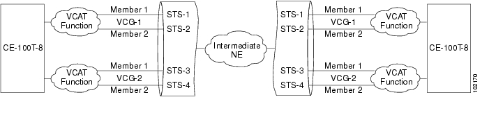
Two types of automatic and manual routing are available for VCAT members: common fiber routing and split routing. CE-Series, FC_MR-4 (both line rate and enhanced mode), and ML-Series cards support common fiber routing. In common fiber routing, all VCAT members travel on the same fibers, which eliminates delay between members. Three protection options are available for common fiber routing: Fully Protected, PCA, and Unprotected. Figure 11-14 shows an example of common fiber routing.
Figure 11-14 VCAT Common Fiber Routing
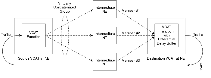
CE-Series cards also support split fiber routing, which allows the individual members to be routed on different fibers or each member to have different routing constraints. This mode offers the greatest bandwidth efficiency and also the possibility of differential delay, which is handled by the buffers on the terminating cards. Four protection options are available for split fiber routing: Fully Protected, PCA, Unprotected, and DRI. Figure 11-15 shows an example of split fiber routing.
Figure 11-15 VCAT Split Fiber Routing
In both common fiber and split fiber routing, each member can use a different protection scheme; however, for common fiber routing, CTC checks the combination to make sure that a valid route exists. If it does not, the user must modify the protection type. In both common fiber and split fiber routing, intermediate nodes treat the VCAT members as normal circuits that are independently routed and protected by the SONET network. At the terminating nodes, these member circuits are multiplexed into a contiguous stream of data.
11.16.3 Link Capacity Adjustment
The CE-100T-8 card supports the link capacity adjustment scheme (LCAS), which is a signaling protocol that allows dynamic bandwidth adjustment of VCAT circuits. When a member fails, a brief traffic hit occurs. LCAS temporarily removes the failed member from the VCAT circuit for the duration of the failure, leaving the remaining members to carry the traffic. When the failure clears, the member circuit is automatically added back into the VCAT circuit without affecting traffic. You can select LCAS during VCAT circuit creation.
Note
Instead of LCAS, the FC_MR-4 (enhanced mode), CE-1000-4 card, and ML-Series cards support software LCAS (SW-LCAS). SW-LCAS is a limited form of LCAS that allows the VCAT circuit to adapt to member failures and keep traffic flowing at a reduced bandwidth. SW-LCAS uses legacy SONET failure indicators like AIS-P and remote defect indication, path (RDI-P) to detect member failure. SW-LCAS removes the failed member from the VCAT circuit, leaving the remaining members to carry the traffic. When the failure clears, the member circuit is automatically added back into the VCAT circuit. For ML-Series cards, SW-LCAS allows circuit pairing over two-fiber BLSRs. With circuit pairing, a VCAT circuit is set up between two ML-Series cards: one is a protected circuit (line protection) and the other is a PCA circuit. For four-fiber BLSRs, member protection cannot be mixed. You select SW-LCAS during VCAT circuit creation. The FC_MR-4 (line rate mode) does not support SW-LCAS.
In addition, you can create non-LCAS VCAT circuits, which do not use LCAS or SW-LCAS. While LCAS and SW-LCAS member cross-connects can be in different service states, all In Group non-LCAS members must have cross-connects in the same service state. A non-LCAS circuit can mix Out of Group and In Group members, as long as the In Group members are in the same service state. Non-LCAS members do not support the OOS-MA,OOG service state; to put a non-LCAS member in the Out of Group VCAT state, use the OOS-MA,DSBLD administrative state.
Note
11.16.4 VCAT Circuit Size
Table 11-16 lists supported VCAT circuit rates and number of members for each card.
Table 11-16 ONS 15454 Card VCAT Circuit Rates and Members
CE-100T-8
VT1.5
1-64
STS-1
1-31
CE-1000-4
STS-1
1-21 1
STS-3
1-7
FC_MR-4 (line rate mode)
STS-1
24 (1 Gbps port)
48 (2 Gbps port)
STS-3c
8 (1 Gbps port)
16 (2 Gbps port)
FC_MR-4 (enhanced mode)
STS-1
1-24 (1 Gbps port)
1-48 (2 Gbps port)
STS-3c
1-8 (1 Gbps port)
1-16 (2 Gbps port)
ML-Series
STS-1, STS-3c, STS-12c
2
1 A VCAT circuit with a CE-Series card as a source or destination and an ML-Series card as a source or destination can have only two members.
Use the Members tab in the Edit Circuit window to add or delete members from a VCAT circuit. The capability to add or delete members depends on the card and whether the VCAT circuit is LCAS, SW-LCAS, or non-LCAS.
•
•
•
•
•
Table 11-17 summarizes the VCAT capabilities for each card.
Table 11-17 ONS 15454 VCAT Card Capabilities
CE-100T-8
LCAS
Yes1
Yes 1
Yes
SW-LCAS
No
No
No
Non-LCAS
Yes2
Yes 2
No
CE-1000-4
LCAS
No
No
No
SW-LCAS
Yes
Yes
Yes
Non-LCAS
Yes 2
Yes 2
No
FC_MR-4 (enhanced mode)
SW-LCAS
Yes
Yes
Yes
Non-LCAS
No
No
No
FC_MR-4 (line mode)
Non-LCAS
No
No
No
ML-Series
SW-LCAS
No
No
No
Non-LCAS
No
No
No
1 When adding or deleting a member from an LCAS VCAT circuit, Cisco recommends that you first put the member in the OOS-MA,OOG service state to avoid service disruptions.
2 For CE-Series cards, you can add or delete members after creating a VCAT circuit with no protection. During the time it takes to add or delete members (from seconds to minutes), the entire VCAT circuit will be unable to carry traffic.
11.17 Bridge and Roll
The CTC Bridge and Roll wizard reroutes live traffic without interrupting service. The bridge process takes traffic from a designated "roll from" facility and establishes a cross-connect to the designated "roll to" facility. When the bridged signal at the receiving end point is verified, the roll process creates a new cross-connect to receive the new signal. When the roll completes, the original cross-connects are released. You can use the bridge and roll feature for maintenance functions such as card or facility replacement, or for load balancing. You can perform a bridge and roll on the following ONS platforms: ONS 15454, ONS 15454 SDH, ONS 15600, ONS 15327, and ONS 15310-CL.
11.17.1 Rolls Window
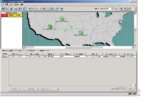
The Rolls window lists information about a rolled circuit before the roll process is complete. You can access the Rolls window by clicking the Circuits > Rolls tabs in either network or node view. Figure 11-16 shows the Rolls window.
Figure 11-16 Rolls Window
The Rolls window information includes:
•
•
•
•
•
Note
–
–
•
•
•
•
•
•
Note
•
•
Note
11.17.2 Roll Status
Table 11-18 lists the roll statuses.
Note
11.17.3 Single and Dual Rolls
Circuits have an additional layer of roll types: single and dual. A single roll on a circuit is a roll on one of its cross-connects. Use a single roll to:
•
•
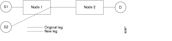
In Figure 11-17, you can select any available STS on Node 1 for a new source.
Figure 11-17 Single Source Roll
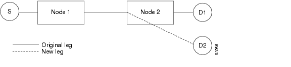
In Figure 11-18, you can select any available STS on Node 2 for a new destination.
Figure 11-18 Single Destination Roll
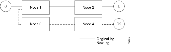
Figure 11-19 shows one circuit rolling onto another circuit at the destination. The new circuit has cross-connects on Node 1, Node 3, and Node 4. CTC deletes the cross-connect on Node 2 after the roll.
Figure 11-19 Single Roll from One Circuit to Another Circuit (Destination Changes)
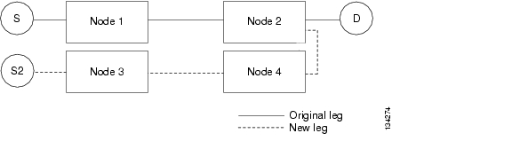
Figure 11-20 shows one circuit rolling onto another circuit at the source.
Figure 11-20 Single Roll from One Circuit to Another Circuit (Source Changes)
Note
A dual roll involves two cross-connects. It allows you to reroute intermediate segments of a circuit, but keep the original source and destination. If the new segments require new cross-connects, use the Bridge and Roll wizard or create a new circuit and then perform a roll.
Dual rolls have several constraints:
•
•
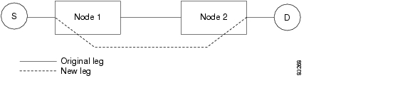
Figure 11-21 illustrates a dual roll on the same circuit.
Figure 11-21 Dual Roll to Reroute a Link
Figure 11-22 illustrates a dual roll involving two circuits.
Figure 11-22 Dual Roll to Reroute to a Different Node
Note
11.17.4 Two Circuit Bridge and Roll
When using the bridge and roll feature to reroute traffic using two circuits, the following constraints apply:
•
•
•
•
11.17.5 Protected Circuits
CTC allows you to roll the working or protect path regardless of which path is active. You can upgrade an unprotected circuit to a fully protected circuit or downgrade a fully protected circuit to an unprotected circuit with the exception of a path protection circuit. When using bridge and roll on path protection circuits, you can roll the source or destination or both path selectors in a dual roll. However, you cannot roll a single path selector.
11.18 Merged Circuits
A circuit merge combines a single selected circuit with one or more circuits. You can merge VT tunnels, VAP circuits, VCAT members, CTC-created circuits, and TL1-created circuits. To merge circuits, you choose a circuit in the CTC Circuits window and the circuits that you want to merge with the chosen (master) circuit on the Merge tab in the Edit Circuits window. The Merge tab shows only the circuits that are available for merging with the master circuit:
•
•
•
•
•
•
•
If all connections from the master circuit and all connections from the merged circuits align to form one complete circuit, the merge is successful. If all connections from the master circuit and some, but not all, connections from the other circuits align to form a single complete circuit, CTC notifies you and gives you the chance to cancel the merge process. If you choose to continue, the aligned connections merge successfully into the master circuit, and the unaligned connections remain in the original circuits. All connections in the completed master circuit use the original master circuit name.
All connections from the master circuit and at least one connection from the other selected circuits must be used in the resulting circuit for the merge to succeed. If a merge fails, the master circuit and all other circuits remain unchanged. When the circuit merge completes successfully, the resulting circuit retains the name of the master circuit.
You can also merge orderwire and user data channel (UDC) overhead circuits, which use the overhead bytes instead of frame payload to transfer data. To merge overhead circuits, you choose the overhead circuits on the network view Provisioning > Overhead Circuits window. You can only merge orderwire and UDC circuits.
11.19 Reconfigured Circuits
You can reconfigure multiple circuits, which is typically necessary when a large number of circuits are in the PARTIAL status. When reconfiguring multiple circuits, the selected circuits can be any combination of DISCOVERED, PARTIAL, DISCOVERED_TL1, or PARTIAL_TL1 circuits. You can reconfigure tunnels, VAP circuits, VLAN-assigned circuits, VCAT circuits, CTC-created circuits, and TL1-created circuits. The Reconfigure command maintains the names of the original cross-connects.
Use the CTC Tools > Circuits > Reconfigure Circuits menu item to reconfigure selected circuits. During reconfiguration, CTC reassembles all connections of the selected circuits and VCAT members into circuits based on path size, direction, and alignment. Some circuits might merge and others might split into multiple circuits. If the resulting circuit is a valid circuit, it appears as a DISCOVERED circuit. Otherwise, the circuit appears as a PARTIAL or PARTIAL_TL1 circuit.
Note
Note
11.20 VLAN Management
In Software Release 4.6 and later, VLANs are populated within topologies to limit broadcasts to each topology rather than to the entire network. Using the Manage VLANs command in the Tools menu, you can view a list of topology hosts and provisioned VLANs. You create VLANs during circuit creation or with the Manage VLANs command. When creating a VLAN, you must identify the topology host (node) where the VLAN will be provisioned. The Manage VLANs command also allows you to delete existing VLANs.
11.21 Server Trails
A server trail is a non-DCC link across a third-party network that connects two CTC network domains. A server trail allows circuit provisioning when no DCC is available. You can create server trails between any two optical or DS-3 ports. The end ports on a server trail can be different types (for example, an OC-3 port can connect to an OC-12 port). Server trails are not allowed on DCC-enabled ports.
Note
The server trail link is bidirectional and can be VT1.5, VT2, STS1, STS-3c, STS-6c, STS-12c, STS-48c, or STS-192c; you cannot upgrade an existing server trail to another size. A server trail link can be one of the following protection types: Preemptible, Unprotected, and Fully Protected. The server trail protection type determines the protection type for any circuits that traverse it. PCA circuits will use server trails with the Preemptible attribute.
When creating circuits or VCATs, you can choose a server trail link during manual circuit routing. CTC may also route circuits over server trail links during automatic routing. VCAT common-fiber automatic routing is not supported.
![]()
![]()
![]()
![]()
![]()
![]()
![]()
![]()
Posted: Thu Oct 25 03:41:22 PDT 2007
All contents are Copyright © 1992--2007 Cisco Systems, Inc. All rights reserved.
Important Notices and Privacy Statement.