|
|

Table Of Contents
2.1 Common Control Card Overview
2.1.3 Cross-Connect Card Compatibility
2.2.2 TCC2 Card-Level Indicators
2.2.3 Network-Level Indicators
2.3.2 TCC2P Card-Level Indicators
2.3.3 Network-Level Indicators
2.4.3 XCVT Hosting DS3XM-6 or DS3XM-12
2.4.4 XCVT Card-Level Indicators
2.5.3 XC10G Hosting DS3XM-6 or DS3XM-12
2.5.4 XC10G Card-Level Indicators
2.5.5 XCVT/XC10G/XC-VXC-10G Compatibility
2.6.1 XC-VXC-10G Functionality
2.6.3 XC-VXC-10G Hosting DS3XM-6 or DS3XM-12
2.6.4 XC-VXC-10G Card-Level Indicators
2.6.5 XC-VXC-10G Compatibility
2.7.1 AIC-I Card-Level Indicators
2.7.2 External Alarms and Controls
2.7.6 Data Communications Channel
Common Control Cards
Note
The terms "Unidirectional Path Switched Ring" and "UPSR" may appear in Cisco literature. These terms do not refer to using Cisco ONS 15xxx products in a unidirectional path switched ring configuration. Rather, these terms, as well as "Path Protected Mesh Network" and "PPMN," refer generally to Cisco's path protection feature, which may be used in any topological network configuration. Cisco does not recommend using its path protection feature in any particular topological network configuration.
This chapter describes Cisco ONS 15454 common control card functions. For installation and turn-up procedures, refer to the Cisco ONS 15454 Procedure Guide.
Chapter topics include:
•
2.1 Common Control Card Overview
The card overview section summarizes card functions and compatibility.
Each card is marked with a symbol that corresponds to a slot (or slots) on the ONS 15454 shelf assembly. The cards are then installed into slots displaying the same symbols. See the "1.17.1 Card Slot Requirements" section on page 1-61 for a list of slots and symbols.
2.1.1 Cards Summary
Table 2-1 lists the common control cards for the Cisco ONS 15454 and summarizes card functions.
Table 2-1 Common Control Card Functions
The Advanced Timing, Communications, and Control (TCC2) card is the main processing center for the ONS 15454 and provides system initialization, provisioning, alarm reporting, maintenance, and diagnostics. It has additional features including supply voltage monitoring, support for up to 84 data communications channel/generic communications channel (DCC/GCC) terminations, and an on-card lamp test.
See the "TCC2 Card" section.
The Advanced Timing, Communications, and Control Plus (TCC2P) card is the main processing center for the ONS 15454 and provides system initialization, provisioning, alarm reporting, maintenance, and diagnostics. It also provides supply voltage monitoring, support for up to 84 DCC/GCC terminations, and an on-card lamp test. This card also has Ethernet security features and 64K composite clock building integrated timing supply (BITS) timing.
See the "TCC2P Card" section.
The Cross Connect Virtual Tributary (XCVT) card is the central element for switching; it establishes connections and performs time-division switching (TDS). The XCVT can manage STS and Virtual Tributary (VT) circuits up to 48c.
See the "XCVT Card" section.
The 10 Gigabit Cross Connect (XC10G) card is the central element for switching; it establishes connections and performs TDS. The XC10G can manage STS and VT circuits up to 192c. The XC10G allows up to four times the bandwidth of XC and XCVT cards.
See the "XC10G Card" section.
The 10 Gigabit Cross Connect Virtual Tributary/Virtual Container (XC-VXC-10G) card serves as the switching matrix for the Cisco 15454 ANSI multiservice platform. The module operates as a superset of the XCVT or XC10G cross-connect module. The XC-VXC-10G card provides a maximum of 1152 STS-1 or 384 VC4 cross-connections and supports cards with speeds up to 10 Gbps.
See the "XC-VXC-10G Card" section.
The Alarm Interface Card-International (AIC-I) provides customer-defined (environmental) alarms with its additional input/output alarm contact closures. It also provides orderwire, user data channels, and supply voltage monitoring.
See the "AIC-I Card" section.
The alarm expansion panel (AEP) board provides 48 dry alarm contacts: 32 inputs and 16 outputs. It can be used with the AIC-I card.
2.1.2 Card Compatibility
Table 2-2 lists the Cisco Transport Controller (CTC) software release compatibility for each common-control card. In the tables below, "Yes" means cards are compatible with the listed software versions. Table cells with dashes mean cards are not compatible with the listed software versions.
Table 2-2 Common-Control Card Software Release Compatibility
Yes
Yes
Yes
Yes
Yes
Yes
Yes
Yes
Yes
—
—
—
—
—
—
—
—
—
—
—
—
—
Yes
Yes
Yes
Yes
Yes
Yes
Yes
Yes
—
—
—
—
—
—
—
Yes
Yes
Yes
Yes
Yes
Yes
Yes
Yes
Yes
Yes
Yes
Yes
Yes
Yes
Yes
Yes
Yes
—
Yes
—
Yes1
Yes 1
Yes 1
Yes
Yes
Yes
Yes
Yes
Yes
Yes
Yes
Yes
—
Yes
—
Yes
Yes
Yes
—
—
—
Yes
Yes
Yes
Yes
Yes
Yes
—
Yes
—
Yes
Yes
Yes
—
—
—
—
—
—
—
—
—
—
—
—
—
Yes
Yes
Yes
Yes
Yes
Yes
Yes
Yes
Yes
Yes
Yes
Yes
Yes
Yes
Yes
No
No
—
—
—
—
—
—
Yes
Yes
Yes
Yes
Yes
Yes
Yes
Yes
Yes
—
—
—
—
—
—
Yes
Yes
Yes
Yes
Yes
Yes
Yes
Yes
Yes
1 The XC card does not support features new to Release 5.0 and greater.
2.1.3 Cross-Connect Card Compatibility
The following tables list the compatible cross-connect cards for each Cisco ONS 15454 common-control card. The tables are organized according to type of common-control card. In the tables below, "Yes" means cards are compatible with the listed cross-connect card. Table cells with dashes mean cards are not compatible with the listed cross-connect card.
Table 2-3 lists the cross-connect card compatibility for each common-control card.
Table 2-3 Common-Control Card Cross-Connect Compatibility
Yes
Yes
—
Yes
Yes
Yes
Yes
Yes
Yes
—3
—3
—3
Yes
—3
—3
—3
Yes
—3
—3
—3
Yes
Yes
Yes
Yes
Yes
Yes
Yes
1 Requires SA-ANSI or SA-HD shelf assembly.
2 The TCC+ is not compatible with Software R4.5 or greater.
3 These cross-connect cards are compatible only during an upgrade.
Table 2-4 lists the cross-connect card compatibility for each electrical card. For electrical card software compatiblilty, see Table 3-2 on page 3-3.
Note
Table 2-4 Electrical Card Cross-Connect Compatibility
Yes
Yes
Yes
Yes
Yes
Yes
Yes
Yes
Yes
Yes
Yes
Yes
Yes
Yes
Yes
Yes
Yes
Yes
Yes
Yes
Yes
—
Yes
Yes
Yes
Yes
Yes
Yes
Yes
Yes
Yes
Yes
Yes
Yes
Yes
Yes
1 Requires a 15454-SA-ANSI or 15454-SA-HD shelf assembly.
Table 2-5 lists the cross-connect card compatibility for each optical card. For optical card software compatibility, see Table 4-2 on page 4-4.
Note
Table 2-5 Optical Card Cross-Connect Compatibility
Yes
Yes
Yes
Yes
Yes
Yes
—
Yes
Yes
Yes
Yes
Yes
Yes
Yes
Yes
Yes
Yes
Yes
Yes
Yes
Yes
Yes
Yes
Yes
Yes
Yes
Yes
—
Yes
Yes
Yes
Yes
Yes
Yes
Yes
Yes
Yes2
Yes
Yes
Yes2
Yes
Yes
Yes
Yes
Yes
Yes
Yes
Yes
—
Yes
Yes
—
Yes
Yes
—
Yes
Yes
—
Yes
Yes
—
Yes
Yes
Yes
Yes
Yes
1 Requires a 15454-SA-ANSI or 15454-SA-HD shelf assembly.
2 Requires Software Release 3.2 and later in Slots 5, 6, 12, 13.
Table 2-6 lists the cross-connect card compatibility for each Ethernet card. For Ethernet card software compatibility, see Table 5-2 on page 5-3.
Note
Table 2-6 Ethernet Card Cross-Connect Compatibility
Yes
—
—
Yes
—
—
Yes
Yes
Yes
Yes
Yes
Yes
Yes, in Slots 5, 6, 12, 13
Yes
Yes
Yes, in Slots 5, 6, 12, 13
Yes
Yes
Yes, in Slots 5, 6, 12, 13
Yes
Yes
Yes, in Slots 5, 6, 12, 13
Yes
Yes
Yes
Yes
Yes
Yes
Yes
Yes
1 Requires a 15454-SA-ANSI or 15454-SA-HD shelf assembly.
Table 2-7 lists the cross-connect card compatibility for each storage area network (SAN) card. For SAN card software compatibility, see the "6.1.3 FC_MR-4 Compatibility" section on page 6-4.
Table 2-7 SAN Card Cross-Connect Compatibility
Yes
Yes
Yes
1 Requires SA-ANSI or SA-HD shelf assembly
2.2 TCC2 Card
Note
The TCC2 card performs system initialization, provisioning, alarm reporting, maintenance, diagnostics, IP address detection/resolution, SONET section overhead (SOH) DCC/GCC termination, and system fault detection for the ONS 15454. The TCC2 also ensures that the system maintains Stratum 3 (Telcordia GR-253-CORE) timing requirements. It monitors the supply voltage of the system.
Note
Note
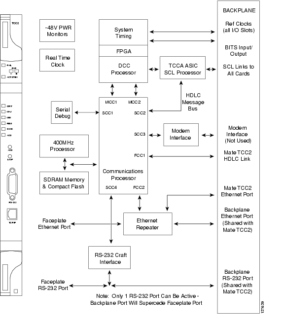
Figure 2-1 shows the faceplate and block diagram for the TCC2 card.
Figure 2-1 TCC2 Card Faceplate and Block Diagram
2.2.1 TCC2 Card Functionality
The TCC2 card supports multichannel, high-level data link control (HDLC) processing for the DCC. Up to 84 DCCs can be routed over the TCC2 card and up to 84 section DCCs can be terminated at the TCC2 card (subject to the available optical digital communication channels). The TCC2 card selects and processes 84 DCCs to facilitate remote system management interfaces.
The TCC2 card also originates and terminates a cell bus carried over the module. The cell bus supports links between any two cards in the node, which is essential for peer-to-peer communication. Peer-to-peer communication accelerates protection switching for redundant cards.
The node database, IP address, and system software are stored in TCC2 card nonvolatile memory, which allows quick recovery in the event of a power or card failure.
The TCC2 card performs all system-timing functions for each ONS 15454. The TCC2 monitors the recovered clocks from each traffic card and two BITS ports (DS1, 1.544 MHz) for frequency accuracy. The TCC2 selects a recovered clock, a BITS, or an internal Stratum 3 reference as the system-timing reference. You can provision any of the clock inputs as primary or secondary timing sources. A slow-reference tracking loop allows the TCC2 to synchronize with the recovered clock, which provides holdover if the reference is lost.
The TCC2 monitors both supply voltage inputs on the shelf. An alarm is generated if one of the supply voltage inputs has a voltage out of the specified range.
Install TCC2 cards in Slots 7 and 11 for redundancy. If the active TCC2 fails, traffic switches to the protect TCC2. All TCC2 protection switches conform to protection switching standards when the bit error rate (BER) counts are not in excess of 1 * 10 exp - 3 and completion time is less than 50 ms.
The TCC2 card has two built-in interface ports for accessing the system: an RJ-45 10BaseT LAN interface and an EIA/TIA-232 ASCII interface for local craft access. It also has a 10BaseT LAN port for user interfaces over the backplane.
Note
Note
Note
2.2.2 TCC2 Card-Level Indicators
The TCC2 faceplate has eight LEDs. Table 2-8 describes the two card-level LEDs on the TCC2 card faceplate.
2.2.3 Network-Level Indicators
Table 2-9 describes the six network-level LEDs on the TCC2 faceplate.
2.3 TCC2P Card
Note
The TCC2P card is an enhanced version of the TCC2 card. For Software Release 5.0 and later, the primary enhancements are Ethernet security features and 64K composite clock BITS timing.
The TCC2P card performs system initialization, provisioning, alarm reporting, maintenance, diagnostics, IP address detection/resolution, SONET SOH DCC/GCC termination, and system fault detection for the ONS 15454. The TCC2P card also ensures that the system maintains Stratum 3 (Telcordia GR-253-CORE) timing requirements. It monitors the supply voltage of the system.
Note
Note
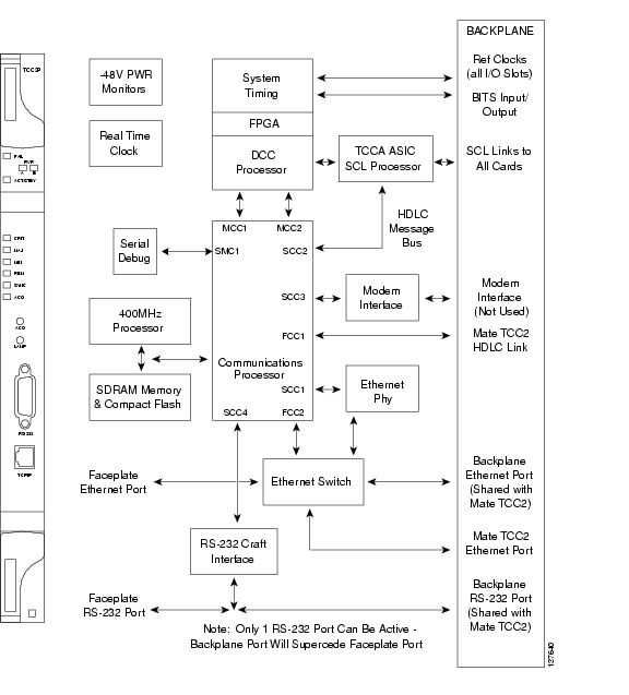
Figure 2-2 shows the faceplate and block diagram for the TCC2P card.
Figure 2-2 TCC2P Faceplate and Block Diagram
2.3.1 TCC2P Functionality
The TCC2P card supports multichannel, high-level data link control (HDLC) processing for the DCC. Up to 84 DCCs can be routed over the TCC2P card and up to 84 section DCCs can be terminated at the TCC2P card (subject to the available optical digital communication channels). The TCC2P selects and processes 84 DCCs to facilitate remote system management interfaces.
The TCC2P card also originates and terminates a cell bus carried over the module. The cell bus supports links between any two cards in the node, which is essential for peer-to-peer communication. Peer-to-peer communication accelerates protection switching for redundant cards.
The node database, IP address, and system software are stored in TCC2P card nonvolatile memory, which allows quick recovery in the event of a power or card failure.
The TCC2P card performs all system-timing functions for each ONS 15454. The TCC2P card monitors the recovered clocks from each traffic card and two BITS ports for frequency accuracy. The TCC2P card selects a recovered clock, a BITS clock, or an internal Stratum 3 reference as the system-timing reference. You can provision any of the clock inputs as primary or secondary timing sources. A slow-reference tracking loop allows the TCC2P card to synchronize with the recovered clock, which provides holdover if the reference is lost.
The TCC2P card supports a 64 kHz + 8 kHz composite clock BITS input (BITS IN) as well as a 6.312-MHz BITS OUT clock. The BITS clock on the system is configurable as DS1 (default), 1.544 MHz, or 64 kHz. The BITS OUT clock runs at a rate determined by the BITS IN clock, as follows:
•
•
•
A BITS output interface configured as 6.312 MHz complies with ITU-T G.703, Appendix II, Table II.4, with a monitor level of -40 dBm +/- 4 dBm.
The TCC2P card monitors both supply voltage inputs on the shelf. An alarm is generated if one of the supply voltage inputs has a voltage out of the specified range.
Install TCC2P cards in Slots 7 and 11 for redundancy. If the active TCC2P card fails, traffic switches to the protect TCC2P card. All TCC2P card protection switches conform to protection switching standards when the BER counts are not in excess of 1 * 10 exp - 3 and completion time is less than 50 ms.
The TCC2P card has two built-in Ethernet interface ports for accessing the system: one built-in RJ-45 port on the front faceplate for on-site craft access and a second port on the backplane. The rear Ethernet interface is for permanent LAN access and all remote access via TCP/IP as well as for Operations Support System (OSS) access. The front and rear Ethernet interfaces can be provisioned with different IP addresses using CTC.
Two EIA/TIA-232 serial ports, one on the faceplate and a second on the backplane, allow for craft interface in TL1 mode.
Note
Note
Note
Note
2.3.2 TCC2P Card-Level Indicators
The TCC2P faceplate has eight LEDs. Table 2-10 describes the two card-level LEDs on the TCC2P faceplate.
2.3.3 Network-Level Indicators
Table 2-11 describes the six network-level LEDs on the TCC2P faceplate.
2.4 XCVT Card
Note
The Cross Connect Virtual Tributary (XCVT) card establishes connections at the STS-1 and VT levels. The XCVT provides STS-48 capacity to Slots 5, 6, 12, and 13, and STS-12 capacity to Slots 1 to 4 and 14 to 17. Any STS-1 on any port can be connected to any other port, meaning that the STS cross-connections are nonblocking.
Figure 2-3 shows the XCVT faceplate and block diagram.
Figure 2-3 XCVT Faceplate and Block Diagram
2.4.1 XCVT Functionality
The STS-1 switch matrix on the XCVT card consists of 288 bidirectional ports and adds a VT matrix that can manage up to 336 bidirectional VT1.5 ports or the equivalent of a bidirectional STS-12. The VT1.5-level signals can be cross connected, dropped, or rearranged. The TCC2/TCC2P card assigns bandwidth to each slot on a per STS-1 or per VT1.5 basis. The switch matrices are fully crosspoint and broadcast supporting.
The XCVT card provides:
•
•
•
•
•
•
The XCVT card works with the TCC2/TCC2P cards to maintain connections and set up cross-connects within the node. The cross-connect cards (such as the XCVT and XC10G), installed in Slots 8 and 10, are required to operate the ONS 15454. You can establish cross-connect (circuit) information through CTC. The TCC2/TCC2P cards establish the proper internal cross-connect information and relay the setup information to the XCVT card.
Caution
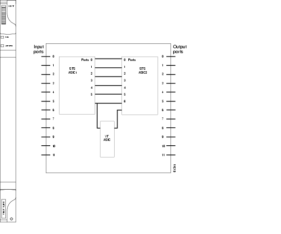
Figure 2-4 shows the cross-connect matrix.
Figure 2-4 XCVT Cross-Connect Matrix
2.4.2 VT Mapping
The VT structure is designed to transport and switch payloads below the DS-3 rate. The ONS 15454 performs VT mapping according to Telcordia GR-253-CORE standards. Table 2-12 shows the VT numbering scheme for the ONS 15454 as it relates to the Telcordia standard.
2.4.3 XCVT Hosting DS3XM-6 or DS3XM-12
A DS3XM card can demultiplex (map down to a lower rate) M13-mapped DS-3 signals into 28 DS-1s that are then mapped to VT1.5 payloads. The VT1.5s can then be cross-connected by the XCVT card. The XCVT card can host a maximum of 336 bidirectional VT1.5s.
2.4.4 XCVT Card-Level Indicators
Table 2-13 shows the two card-level LEDs on the XCVT card faceplate.
2.5 XC10G Card
Note
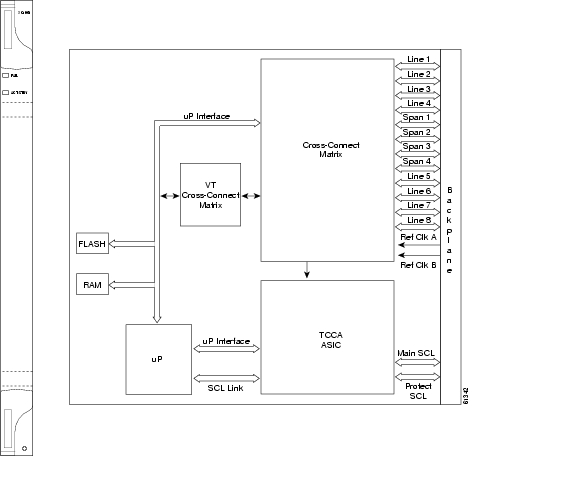
The 10 Gigabit Cross Connect (XC10G) card establishes connections at the STS-1 and VT levels. The XC10G provides STS-192 capacity to Slots 5, 6, 12, and 13, and STS-48 capacity to Slots 1 to 4 and 14 to 17. The XC10G allows up to four times the bandwidth of the XCVT cards. The XC10G provides a maximum of 576 STS-1 cross-connections through 1152 STS-1 ports. Any STS-1 on any port can be connected to any other port, meaning that the STS cross-connections are nonblocking.
Figure 2-5 shows the XC10G faceplate and block diagram.
Figure 2-5 XC10G Faceplate and Block Diagram
2.5.1 XC10G Functionality
The XC10G card manages up to 672 bidirectional VT1.5 ports and 1152 bidirectional STS-1 ports. The TCC2/TCC2P cards assign bandwidth to each slot on a per STS-1 or per VT1.5 basis.
Two cross-connect cards, installed in Slots 8 and 10, are required to operate the ONS 15454. You can establish cross-connect (circuit) information through the CTC. The cross-connect card establishes the proper internal cross-connect information and sends the setup information to the cross-connect card.
The XC10G card provides:
•
•
•
•
•
•
Caution
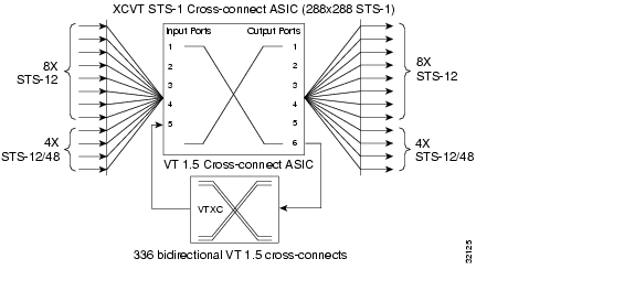
Figure 2-6 shows the cross-connect matrix.
Figure 2-6 XC10G Cross-Connect Matrix
2.5.2 VT Mapping
The VT structure is designed to transport and switch payloads below the DS-3 rate. The ONS 15454 performs VT mapping according to Telcordia GR-253-CORE standards. Table 2-14 shows the VT numbering scheme for the ONS 15454 as it relates to the Telcordia standard.
2.5.3 XC10G Hosting DS3XM-6 or DS3XM-12
A DS3XM card can demultiplex (map down to a lower rate) M13-mapped DS-3 signals into 28 DS-1s that are then mapped to VT1.5 payloads. The VT1.5s can then be cross-connected by the XC10G card. The XC10G card can host a maximum of 336 bidirectional VT1.5s.
2.5.4 XC10G Card-Level Indicators
Table 2-15 describes the two card-level LEDs on the XC10G faceplate.
2.5.5 XCVT/XC10G/XC-VXC-10G Compatibility
The XC10G and XC-VXC-10G cards support the same features as the XCVT card. The XC10G or XC-VXC-10G cards are required for OC-192, OC-48 any-slot (AS), OC3-8, and OC12-4 operation. Do not use the XCVT card if you are using an OC-192, OC3-8, or OC12-4 card or if you install an OC-48 AS card in Slots 1 to 4 or 14 to 17.
Note
If you are using Ethernet cards, the E1000-2-G or the E100T-G must be used when the XC10G or XC-VXC-10G cross-connect card is in use. Do not pair an XCVT card with an XC10G or XC-VXC-10G card. When upgrading from an XCVT to the XC10G or XC-VXC-10G card, refer to the "Upgrade Cards and Spans" chapter in the Cisco ONS 15454 Procedure Guide for more information.
2.6 XC-VXC-10G Card
Note
The XC-VXC-10G card establishes connections at the STS and VT levels. The XC-VXC-10G provides STS-192 capacity to Slots 5, 6, 12, and 13, and STS-48 capacity to Slots 1 to 4 and 14 to 17. Any STS-1 on any port can be connected to any other port, meaning that the STS cross-connections are nonblocking.
Figure 2-7 shows the XC-VXC-10G faceplate and block diagram.
Figure 2-7 XC-VXC-10G Faceplate and Block Diagram
2.6.1 XC-VXC-10G Functionality
The XC-VXC-10G card manages up to 1152 bidirectional high-order STS-1 ports. In addition, it is able to simultaneously manage one of the following low-order VT cross-connect arrangements:
•
•
•
The TCC2/TCC2P card assigns bandwidth to each slot on a per STS-1, per VT1.5, or per VT2 basis. The switch matrices are fully crosspoint and broadcast supporting.
At the STS level (high-order cross-connect), the XC-VXC-10G is always non-blocking (any STS-1 from the system can be cross-connected to any other STS-1 without limitation up to 1152 bidirectional STS-1 ports (576 STS-1 cross-connects).
In addition, for "mixed" VT1.5 and VT2 grooming, 50% of the available VT resources (ports) are allocated to each VT circuit type. The following three modes are supported (only one mode is available at a time):
•
•
•
The XC-VXC-10G card provides:
•
•
•
•
•
•
•
•
•
Note
The XC-VXC-10G supports errorless side switches (switching from one XC-VXC-10G on one side of the shelf to the other XC-VXC-10G on the other side of the shelf) when the switch is initiated through software and the shelf is equipped with TCC2/TCC2P cards.
Cross-connect and provisioning information is established through the user interface on the TCC2/TCC2P card. In turn, the TCC2/TCC2P card establishes the proper internal cross-connect information and relays the setup information to the XC-VXC-10G card so that the proper cross-connection is established within the system.
The XC-VXC-10G card is deployed in Slots 8 or 10. Upgrading a system to an XC-VXC-10G from an earlier cross-connect module type is performed in-service, with hitless operation (less than 50-ms impact to any traffic). The XC-VXC-10G can be used with either the standard ANSI shelf assembly (15454-SA- ANSI) or high-density shelf assembly (15454-SA-HD).
Caution
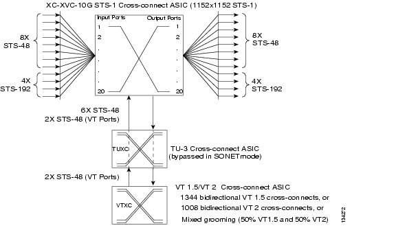
Figure 2-8 shows the XC-VXC-10G cross-connect matrix.
Figure 2-8 XC-VXC-10G Cross-Connect Matrix
2.6.2 VT Mapping
The VT structure is designed to transport and switch payloads below the DS-3 rate. The ONS 15454 performs VT mapping according to Telcordia GR-253-CORE standards. Table 2-14 shows the VT numbering scheme for the ONS 15454 as it relates to the Telcordia standard.
2.6.3 XC-VXC-10G Hosting DS3XM-6 or DS3XM-12
A DS3XM card can demultiplex (map down to a lower rate) M13-mapped DS-3 signals into 28 DS-1s that are then mapped to VT1.5 payloads. The VT1.5s can then be cross-connected by the XC-VXC-10G card. The XC-VXC-10G card can host a maximum of 1344 bidirectional VT1.5s.
2.6.4 XC-VXC-10G Card-Level Indicators
Table 2-17 describes the two card-level LEDs on the XC-VXC-10G faceplate.
2.6.5 XC-VXC-10G Compatibility
The XC-VXC-10G card supports the same features as the XC10G card. Either the XC10G or XC-VXC-10G card is required for OC-192, OC3-8, and OC12-4 operation and OC-48 AS operation.
If you are using Ethernet cards, the E1000-2-G or the E100T-G must be used when the XC-VXC-10G cross-connect card is in use. When upgrading from an XC10G card to an XC-VXC-10G card, refer to the "Upgrade Cards and Spans" chapter in the Cisco ONS 15454 Procedure Guide for more information. Also refer to the "Card Compatibility" section.
2.7 AIC-I Card
Note
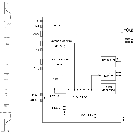
The optional Alarm Interface Controller-International (AIC-I) card provides customer-defined (environmental) alarms and controls and supports local and express orderwire. It provides 12 customer-defined input and 4 customer-defined input/output contacts. The physical connections are through the backplane wire-wrap pin terminals. If you use the additional AEP, the AIC-I card can support up to 32 inputs and 16 outputs, which are connected on the AEP connectors. A power monitoring function monitors the supply voltage (-48 VDC). Figure 2-9 shows the AIC-I faceplate and a block diagram of the card.
Figure 2-9 AIC-I Faceplate and Block Diagram
2.7.1 AIC-I Card-Level Indicators
Table 2-18 describes the eight card-level LEDs on the AIC-I card faceplate.
2.7.2 External Alarms and Controls
The AIC-I card provides input/output alarm contact closures. You can define up to twelve external alarm inputs and 4 external alarm inputs/outputs (user configurable). The physical connections are made using the backplane wire-wrap pins. See the "1.12 Alarm Expansion Panel" section on page 1-47 for information about increasing the number of input/output contacts.
LEDs on the front panel of the AIC-I indicate the status of the alarm lines, one LED representing all of the inputs and one LED representing all of the outputs. External alarms (input contacts) are typically used for external sensors such as open doors, temperature sensors, flood sensors, and other environmental conditions. External controls (output contacts) are typically used to drive visual or audible devices such as bells and lights, but they can control other devices such as generators, heaters, and fans.
You can program each of the twelve input alarm contacts separately. You can program each of the sixteen input alarm contacts separately. Choices include:
•
•
•
•
You cannot assign the fan-tray abbreviation for the alarm; the abbreviation reflects the generic name of the input contacts. The alarm condition remains raised until the external input stops driving the contact or you provision the alarm input.
The output contacts can be provisioned to close on a trigger or to close manually. The trigger can be a local alarm severity threshold, a remote alarm severity, or a virtual wire:
•
•
•
You can also program the output alarm contacts (external controls) separately. In addition to provisionable triggers, you can manually force each external output contact to open or close. Manual operation takes precedence over any provisioned triggers that might be present.
Note
2.7.3 Orderwire
Orderwire allows a craftsperson to plug a phoneset into an ONS 15454 and communicate with craftspeople working at other ONS 15454s or other facility equipment. The orderwire is a pulse code modulation (PCM) encoded voice channel that uses E1 or E2 bytes in section/line overhead.
The AIC-I allows simultaneous use of both local (section overhead signal) and express (line overhead signal) orderwire channels on an SDH ring or particular optics facility. Express orderwire also allows communication via regeneration sites when the regenerator is not a Cisco device.
You can provision orderwire functions with CTC similar to the current provisioning model for DCC/GCC channels. In CTC, you provision the orderwire communications network during ring turn-up so that all NEs on the ring can reach one another. Orderwire terminations (that is, the optics facilities that receive and process the orderwire channels) are provisionable. Both express and local orderwire can be configured as on or off on a particular SONET facility. The ONS 15454 supports up to four orderwire channel terminations per shelf. This allows linear, single ring, dual ring, and small hub-and-spoke configurations. Keep in mind that orderwire is not protected in ring topologies such as bidirectional line switched rings (BLSRs) and path protection configurations.
Caution
The ONS 15454 implementation of both local and express orderwire is broadcast in nature. The line acts as a party line. Anyone who picks up the orderwire channel can communicate with all other participants on the connected orderwire subnetwork. The local orderwire party line is separate from the express orderwire party line. Up to four OC-N facilities for each local and express orderwire are provisionable as orderwire paths.
Note
The AIC-I supports selective dual tone multifrequency (DTMF) dialing for telephony connectivity, which causes one AIC-I card or all ONS 15454 AIC-I cards on the orderwire subnetwork to "ring." The ringer/buzzer resides on the AIC-I. There is also a "ring" LED that mimics the AIC-I ringer. It flashes when a call is received on the orderwire subnetwork. A party line call is initiated by pressing *0000 on the DTMF pad. Individual dialing is initiated by pressing * and the individual four-digit number on the DTMF pad.
Table 2-19 shows the pins on the orderwire connector that correspond to the tip and ring orderwire assignments.
Table 2-19 Orderwire Pin Assignments
1
Four-wire receive ring
2
Four-wire transmit tip
3
Two-wire ring
4
Two-wire tip
5
Four-wire transmit ring
6
Four-wire receive tip
When provisioning the orderwire subnetwork, make sure that an orderwire loop does not exist. Loops cause oscillation and an unusable orderwire channel.
Figure 2-10 shows the standard RJ-11 connectors used for orderwire ports. Use a shielded RJ-11 cable.
Figure 2-10 RJ-11 Connector
2.7.4 Power Monitoring
The AIC-I card provides a power monitoring circuit that monitors the supply voltage of -48 VDC for presence, undervoltage, or overvoltage.
2.7.5 User Data Channel
The user data channel (UDC) features a dedicated data channel of 64 kbps (F1 byte) between two nodes in an ONS 15454 network. Each AIC-I card provides two user data channels, UDC-A and UDC-B, through separate RJ-11 connectors on the front of the AIC-I card. Use an unshielded RJ-11 cable. Each UDC can be routed to an individual optical interface in the ONS 15454. For UDC circuit provisioning, refer to the "Create Circuits and VT Tunnels" chapter in the Cisco ONS 15454 Procedure Guide.
The UDC ports are standard RJ-11 receptacles. Table 2-20 lists the UDC pin assignments.
Table 2-20 UDC Pin Assignments
1
For future use
2
TXN
3
RXN
4
RXP
5
TXP
6
For future use
2.7.6 Data Communications Channel
The DCC features a dedicated data channel of 576 kbps (D4 to D12 bytes) between two nodes in an ONS 15454 network. Each AIC-I card provides two DCCs, DCC-A and DCC-B, through separate RJ-45 connectors on the front of the AIC-I card. Use a shielded RJ-45 cable. Each DCC can be routed to an individual optical interface in the ONS 15454.
The DCC ports are standard RJ-45 receptacles. Table 2-21 lists the DCC pin assignments.
Table 2-21 DCC Pin Assignments
1
TCLKP
2
TCLKN
3
TXP
4
TXN
5
RCLKP
6
RCLKN
7
RXP
8
RXN
![]()
![]()
![]()
![]()
![]()
![]()
![]()
![]()
Posted: Thu Oct 25 03:51:13 PDT 2007
All contents are Copyright © 1992--2007 Cisco Systems, Inc. All rights reserved.
Important Notices and Privacy Statement.