|
|

Table Of Contents
2.1 Setting up TL1 Communication
2.2.2 TAP Creation and Deletion
2.2.3 Connect Test Access Points
2.2.5 Retrieve Test Access Point Information
2.2.6 Disconnect Test Access Points
2.2.7 Delete Test Access Points
2.2.8 Test Access Configurations
2.2.9 Test Access Mode Definitions
2.2.10 Unmapped AID Test Access Point Connections
2.3.1 Gateway Network Element Topology
2.3.2 ONS 15454, ONS 15327 and ONS 15310-CL Gateway
2.3.4 Implementing TL1 Gateway
2.4.1 Path Protection Topology
2.4.2 Path Protection Cross-Connections
2.4.3 Ring-to-Ring Interconnection
2.4.4 Path Protection to Path Protection Connection Example
2.4.5 Path Protection to Two-Fiber BLSR Connection Example
2.4.6 Two-Fiber BLSR to Path Protection Connection Example
2.4.7 Two-Fiber BLSR to Two-Fiber BLSR Connection Example
2.4.8 Two-Fiber BLSR to Four-Fiber BLSR Connection Example (ONS 15454)
2.4.9 Path Protection to Four-Fiber BLSR Connection Example (ONS 15454)
2.4.10 1-Way Drop and Continue
2.4.11 Node 1 Configuration Example (Source Node)
2.4.12 Node 2 Configuration Example (Drop and Continue Node)
2.4.13 Node 3 Configuration Example (Destination Node)
2.5.1 Provision a PCA Cross-Connection
2.5.2 Retrieve a PCA Cross-Connection
2.6.4 Downloading New Software
2.6.6 Remote Software Download/Activation Using the GNE
2.7.1 Create a PM Schedule and Receive an Autonomous PM Report
2.7.3 Enable or Disable a TL1 Session to Receive Autonomous PM Reports
2.8.2 Bridge and Roll TL1 Commands
2.8.3 2-Way Circuit Single Roll and Dual Roll Procedures
2.8.4 1-Way Circuit Single Roll and Dual Roll Procedures
2.8.5 Protection Rolling Procedures
2.9 1:N Low-Density to 1:N High-Density Upgrade
2.10 Remote Monitoring-Managed PMs
2.10.4 RTRV-RMONTH-<MOD2_RMON>
2.10.5 REPT EVT <MOD2ALM> for Threshold Crossing Events
2.10.11 MONTYPE Defined for Ethernet Statistics and Condition Type for TCA
2.10.13 Notes for DWDM Card Types
2.11 Rules for Framing Type Autoprovisioning in CTC Versus TL1
2.12 Provisioning Rules for Transponder and Muxponder Cards
2.12.2 Payload Provisioning Rules
2.12.3 OC-N Payload Provisioning Parameters
2.12.4 Termination Mode Provisioning Rules
2.12.5 Wavelength Provisioning Rules
2.12.6 Regeneration Group Provisioning Rules
2.12.7 DCC/GCC Provisioning Rules
2.12.8 G.709 OTN, FEC and OTN SDBER/SFBER Provisioning Rules
2.12.9 Synchronization Provisioning Rules
2.12.10 Section Trace Provisioning (J0) Rules
2.12.11 Trail Trace Identification Provisioning Rules
2.12.12 PM and Alarm Threshold Provisioning Rules
2.12.13 Y-Cable Protection Group Provisioning Rules
2.12.14 Splitter Protection Group Provisioning Rules
2.12.15 Loopback Provisioning Rules
2.12.16 Automatic Laser Shutdown Provisioning Rules
2.12.17 Port State Model Provisioning Rules
2.12.18 SONET-Related Provisioning Rules
2.12.19 Overhead Circuit Provisioning Rules
2.12.20 Hardware Limitation Rules
Procedures and Provisioning
Note
The terms "Unidirectional Path Switched Ring" and "UPSR" may appear in Cisco literature. These terms do not refer to using Cisco ONS 15xxx products in a unidirectional path switched ring configuration. Rather, these terms, as well as "Path Protected Mesh Network" and "PPMN," refer generally to Cisco's path protection feature, which may be used in any topological network configuration. Cisco does not recommend using its path protection feature in any particular topological network configuration.
This chapter provides TL1 procedures and provisioning for the Cisco ONS 15454, ONS 15327, ONS 15310-CL and ONS 15600.
•
•
•
•
•
2.1 Setting up TL1 Communication
The period during which a user is logged into the node is called a session. There are three options you can use to open a session (login):
•
•
•
The TL1 password (PID) is masked when accessing a TL1 session using any of these options. When you logout of any of these options, you are closing a session. The ONS 15454, ONS 15327 and ONS 15310-CL allow a maximum of 20 (19 telnet sessions and one craft session) concurrent TL1 sessions using any one or any combination of the options listed above. The ONS 15600 supports a maximum of 20 (18 telnet sessions and 2 serial connections) concurrent TL1 sessions on the Customer Access Panel (CAP). For information on issuing commands to multiple nodes, see the "TL1 Gateway" section.
2.1.1 Open a TL1 session
Use the following procedures to open a TL1 session via the CTC, telnet, or craft interface. In the procedures the Activate and Cancel User commands are shown in their input format. For more information about these and other commands and messages, refer to the Cisco ONS SONET TL1 Command Guide.
Open a TL1 Session Through CTC
Step 1
Step 2
Step 3
Step 4
•
•
on the toolbar.
Step 5
Step 6
A TL1 interface window opens. There are three sub-windows in the TL1 interface window: Request History, Message Log/Summary Log, and TL1 request. Type commands in the TL1 request window. You will see responses in the Message log window. The Request History window allows you to recall previous commands by double-clicking on them.
Step 7
Step 8
ACT-USER:[<TID>]:<UID>:<CTAG>::<PID>; and press Enter.
Note
Step 9
CANC-USER:[<TID>]:<USERID>:<CTAG>; and press Enter.
Open a TL1 Session Through Telnet
To communicate with the ONS NE using TL1 commands using a telnet session over a craft interface or a LAN connection, you can choose from several ports.
•
•
•
Step 1
Step 2
TELNET <NODE IP ADDRESS OR NODE NAME> <PORT NUMBER> and press Enter.
The Node IP address or Node Name refers to the IP address or Node Name of the node you want to communicate with. Port number is the port (2361, 3082, or 3083) where TL1 commands are understood. If the connection is successful, a screen opens with a prompt.
Step 3
ACT-USER:[<TID>]:<UID>:<CTAG>::<PID>;
Note
Step 4
CANC-USER:[<TID>]:<USERID>:<CTAG>;
Open a TL1 Session Through Craft Interface
ONS 15454, ONS 15327 and ONS 15310-CL
The TCC2/TCC2P, XTC and 15310-CL-CTX cards have two built-in interface ports for accessing the ONS 15454, ONS 15327 and ONS 15310-CL respectively. With one RJ-45 LAN connection you can access the system using a standard browser interface. In the browser interface, you can perform local and remote Operations, Administration, Maintenance, and Provisioning (OAM&P) functions and open a VT100 emulation window to enter TL1 commands. If a browser is not available, you can access the system using a nine-pin RS-232 port. The RS-232 port supports VT100 emulation such that TL1 commands can be entered directly without a browser.
Step 1
Step 2
•
•
•
•
•
Step 3
Step 4
ACT-USER:[<TID>]:<UID>:<CTAG>::<PID>;
Note
Step 5
CANC-USER:[<TID>]:<USERID>:<CTAG>;
ONS 15600
The TSC card has one RJ-45 port of the faceplate. The RJ-45 port allows you to access the system using a standard web browser. You must use the RJ-45 port on the active TSC. While using the web browser, you can perform local and remote Operations, Administration, Maintenance and Provisioning (OAM&P) functions.
If a browser is not available, you can access the system using one of the two RS-232 ports on the Customer Access Panel (CAP). Each RS-232 port supports VT100 emulation so that you can enter TL1 commands directly without using a web browser. Each RS-232 port supports its own TL1 session.
Because the CAP RS-232 port is set up as a DTE interface, you must use a 3-pair swapping null modem adapter so that the TXD/RXC, DSR/DTR, and CTS/RTS pins are swapped when connecting to the serial ports. The null modem adapter connects the CAP RS-232 port (male configuration) and the serial cable (female configuration). Table 2-1 lists the null modem adapter pin assignments.
Table 2-1 Null Modem Adapter Pin Assignments
NC1
1
NC
RXD
2
3
TXD
3
2
DTR
4
6
GND
5
5
DSR
6
4
RTS
7
8
CTS
8
7
NC
9
NC
1 NC is Not Connected.
Step 1
Step 2
Step 3
•
–
–
–
–
–
•
tip -9600 /dev/ttyb (or ttya depending on where serial cable is connected)
Step 4
Step 5
ACT-USER:[<TID>]:<UID>:<CTAG>::<PID>;
Note
Step 6
CANC-USER:[<TID>]:<USERID>:<CTAG>;
2.2 Test Access
Note
Note
The test access (TACC) feature allows a third-party Broadband Remote Test Unit (BRTU) to create non-intrusive test access points (TAPs) to monitor the circuits on the ONS 15454, ONS 15327 and ONS 15600 for errors. The test access feature also allows the circuit to be split (intrusive), so that the transmission paths can be tested for bit errors via the use of various bit test patterns. The two BRTUs supported by the ONS 15454, ONS 15327 and ONS 15600 are the Hekimian/Spirent BRTU-93 (6750) and the TTC/Acterna Centest 650.
The test access functionality provides TL1 commands for creating and deleting TAPs, connecting or disconnecting TAPs to circuit cross-connects and changing the mode of test access on the ONS 15454, ONS 15327 and ONS 15600. You can view test access information in CTC; in node view click the Maintenance > Test Access tabs.
Refer to Telcordia document GR-834-CORE, Network Maintenance: Access and Testing and GR-1402-CORE, Network Maintenance: Access Testing - DS3 HCDS TSC/RTU and DTAU Functional Requirements for more information about Test Access.
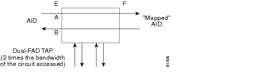
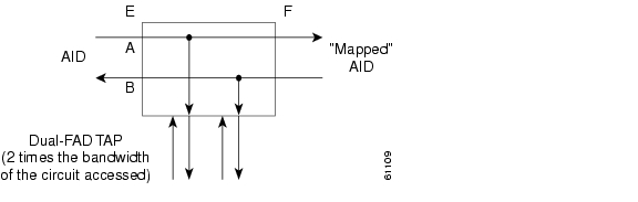
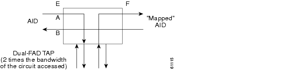
A TAP provides the capability of connecting the circuit under test to a BRTU. This connection initially provides in-service monitoring capability to permit the tester to determine that the circuit under test is idle. The monitor connection should not disturb the circuit under test. The access point and remote test unit (RTU) also provide the capability of splitting a circuit under test. A split consists of breaking the transmission path of the circuit under test. This is done out of service. The two sides of the access point are called the Equipment (E) and Facility (F) directions. For a 4-wire or 6-wire circuit, the transmission pairs within the access point are defined as the A and B pairs. The circuit under test should be wired into the access point so the direction of transmission on the A pair is from E to F, and the transmission direction for the B pair is from F to E ( Figure 2-1).
Figure 2-1 Circuit With No Access Dual FAD TAP
A dual FAD (facility access digroup) TAP uses twice the bandwidth of the circuit under test. This can be specified by the TAPTYPE parameter as shown in ED-<MOD2> command syntax in the "TAP Creation and Deletion" section. The values are SINGLE/DUAL. It defaults to DUAL.
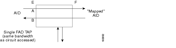
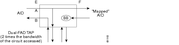
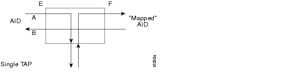
A single FAD TAP uses half the bandwidth as that of the dual FAD, for example, it will use the same bandwidth as the circuit accessed for the TAP creation. This can be specified by the TAPTYPE parameter as shown in the "TAP Creation and Deletion" section. The values are SINGLE/DUAL. The MONEF, SPLTAB and SPLTEF modes are not supported by single FAD TAPs ( Figure 2-2).
Figure 2-2 Circuit With No Access Single FAD TAP
2.2.1 Test Access Terminology
BRTU—Broadband remote test unit
DFAD—Dual facility access digroup
FAD—Facility access digroup
FAP—Facility access path
LOOPE—Split/loop access on A and B paths equipment side
LOOPF—Split/loop access on A and B paths facility side
MONE—Monitor access with signal detector on A path
MONF—Monitor access with signal detector on B path
MONEF—Monitor access with signal detector on A and B paths
QRS—Quasi-random signal (bit test pattern)
SPLTA—Split access on A path with signal detector from equipment, QRS on facility side
SPLTB—Split access on B path with signal detector from equipment, QRS on equipment side
SPLTAB—Split access on A and B paths for testing in both equipment and facility directions
SPLTE—Split access on A and B paths with signal detector from equipment, QRS on equipment side
SPLTF—Split access on A and B paths with signal detector from equipment, QRS on facility side
SPLTEF—Split access on A and B paths for testing in both equipment and facility directions
TACC—Test access
TAP—Test access path/point
Path Naming Conventions:
E—Equipment test access point direction
F—Facility test access point direction
A—Transmission path (the direction of transmission on the A pair is from E to F)
B—Transmission path (the transmission direction for the B pair is from F to E)
2.2.2 TAP Creation and Deletion
TL1 supports commands to create, delete, connect, change, retrieve, and disconnect TAPs.
2.2.2.1 ED-<rr>
The edit command (ED-<rr>) is used to change an existing port, STS, or VT to a TAP.
Input Format:
ED- (T1, T3, STS1, STS3c, STS6c, STS9c, STS12c, STS24c, STS48c, STS192c, VT1, DS1):[<TID>]:<AID>:<CTAG>[:::TACC=<TACC>][TAPTYPE=<TAPTYPE>];
Edit an existing port, STS, or VT and change it to a TAP so it can be used when requesting TACC connections. Includes a new optical parameter TACC=n that defines the port, STS, or VT as a TAP with a selected unique TAP number. This TAP number will be used when requesting test access connections to circuit cross-connections under test. The TAP creation will fail if there is a cross-connection already on the port, STS, or VT.
Note
•
•
The following list applies to TAP numbers:
•
•
•
2.2.2.2 ED-T1
When the ED-T1 command is issued with a specified TACC value for a given T1 port/facility, a dual facility access group (DFAD) is created by using the specified port/facility and the consecutive port/facility.
The command in example Example 2-1 creates a DFAD on FAC-1-1 and FAC-1-2.
Example 2-1 ED-T1::FAC-1-1:12:::TACC=1;
DV9-99 1970-01-02 03:16:11
M 12 COMPLD
;
Note
2.2.2.3 ED-T3
When the ED-T3 command is issued with a specified TACC value for a given T3 port/facility, a DFAD is created by using the specified port/facility and the consecutive port/facility.
The command in Example 2-2 creates a T3 DFAD on FAC-2-1 and FAC-2-2.
Example 2-2 ED-T3::FAC-2-1:12:::TACC=2;
DV9-99 1970-01-02 03:16:11
M 12 COMPLD
;
Note
2.2.2.4 ED-DS1
When the ED-DS1 command is issued with a specified TACC value for a given DS1 facility on a DS3XM, a DFAD is created by using the specified facility and the consecutive port/facility.
The command in Example 2-3 creates DFAD on DS1-2-1-1 and DS1-2-1-2.
Example 2-3 ED-DS1::DS1-2-1-1:12:::TACC=3;
DV9-99 1970-01-02 03:16:11
M 12 COMPLD
;
Note
2.2.2.5 ED-STSn
When the ED-STSn command is issued for a TACC it assigns the STS for the first two-way test access connection and STS+1 as the second 2-way connection. For STS3c, STS9c, STS12c, STS24c, and STS48c the next consecutive STS of same width is chosen. The TAP creation will fail if either of the consecutive STSs are not available.
The command in Example 2-4 creates a TAP on STS-5-1 and STS-5-2.
Example 2-4 ED-STS1::STS-5-1:12:::TACCC=4
DV9-99 1970-01-02 03:16:11
M 12 COMPLD
;
Note
The command in Example 2-5 creates an STS24C dual TAP on STS-6-1 and STS-6-25.
Example 2-5 ED-STS24C::STS-6-1:12:::TACC=5:
DV9-99 1970-01-02 03:16:11
M 12 COMPLD
;
Note
2.2.2.6 ED-VT1
When the ED-VT1 command is issued for a TACC, a VT TAP is created. The specified VT AID is taken as the first VT connection, the second VT connection is made by incrementing the VT group and keeping the VT number the same.
The command in Example 2-6 creates a VT TAP on VT1-1-1-1-1 and VT1-1-1-2-1.
Example 2-6 ED-VT1-1-1-1-1:12:::TACC=6;
DV9-99 1970-01-02 03:16:11
M 12 COMPLD
;
Note
2.2.3 Connect Test Access Points
The CONN-TACC command (CONN-TACC-<rr>) is used to make a connection between the TAP and the circuit or cross-connect under test.
Input Format: CONN-TACC-(T1, T3, STS1, STS3C, STS6C, STS9C, STS12C, STS24C, STS48C, STS192c, VT1,DS1):[<TID>]:<AID>:<CTAG>::<TAP>:MD=<MD>;
Connect the port/STS/VT defined by <AID> to the port/STS/VT defined by the <TAP> number. The mode of test access to the circuit/cross-connect is specified by <MD>. The modes can be either of monitor (non-intrusive), split or loop (intrusive) modes. The various modes are described in the "Test Access Mode Definitions" section.
Note
Note
Error Codes Supported:
RTBY—Requested TAP busy
RTEN—Requested TAP does not exist
SCAT—Circuit is already connected to another TAP
SRCN—Requested condition already exists
IIAC—Invalid access identifier (AID)
EANS—Access not supported
SRAC—Requested access configuration is invalid
The command in Example 2-7 creates a connection between TAP with number one and the port/facility FAC-1-3 with access mode as MONE. The various modes are described in the "Test Access Mode Definitions" section.
Example 2-7 CONN-TACC-T1::FAC-1-3:12::1:MD=MONE;
DV9-99 1970-01-02 02:51:54
M 12 COMPLD
1
;2.2.4 Change Access Mode
The CHG-ACCMD command (CHG-ACCMD-<rr>) is used to change the access mode.
Input Format: CHG-ACCMD-(T1, T3, STS1, STS3C, STS6C, STS9C, STS12C, STS24C, STS48C, STS192c, VT1, DS1):[<TID>]:<TAP>:<CTAG>::<MD>;
Change the type of test access. This might be a change from monitoring the data to inserting data into the STS. This command can only be applied to an existing TAP connection. If a TAP connection does not exist, a RTEN error is returned.
Error codes supported:
SRCN—Requested condition already exists
SRAC—Requested access configuration is invalid
RTEN—Requested TAP does not exist
The command in Example 2-8 changes the access mode of TAP 1 to LOOPE.
Example 2-8 CHG-ACCMD-T1::1:12::LOOPE;
DV9-9 1970-01-02 02:59:43
M 12 COMPLD
;
Note
Note
2.2.5 Retrieve Test Access Point Information
2.2.5.1 RTRV-<rr>
Note
The RTRV-<rr> command retrieves TAP information.
Input Format: RTRV-(T1, T3, STS1, STS3C, STS6C, STS9C, STS12C, STS24C, STS48C, STS192c, VT1, DS1):[<TID>]:<AID>:<CTAG>;
This command is modified to include the return of a TAP number if the requested <AID> is defined as a TAP. An optional TACC=<TAPNUMBER> will appear in the output list if the requested <AID> is defined as a TAP.
Example 2-9 RTRV-T1::FAC-1-1:12;
dv9-99 1970-01-02 02:49:16
M 12 COMPLD
"FAC-1-1::LINECDE=AMI,FMT=D4,LBO=0-131,TACC=1,TAPTYPE=DUAL:OOS"
;Parameter definitions:
•
•
•
•
•
•
2.2.5.2 RTRV-TACC
RTRV-TACC:[<TID>]:<TAP>:<CTAG>;
This command can also be used to retrieve details associated with a TAP. The TAP is identified by the TAP number. The ALL input TAP value means that the command will return all the configured TACCs in the NE.
Example 2-10 RTRV-TACC:CISCO:241:CTAG;
TID-000 1998-06-20 14:30:00
M 001 COMPLD
"241:STS-2-1-1.STS-2-2,MONE,STS-12-1-1,STS-13-1-1"
;Parameter Definitions:
•
•
•
•
•
•
2.2.6 Disconnect Test Access Points
TAPs can be disconnected in the following ways:
•
•
•
•
The DISC-TACC command disconnects the <TAP> and puts the connection back to its original state (no access). To issue the DISC-TACC command, follow the input format and examples shown below:
Input Format: DISC-TACC:[<TID>]:<TAP>:<CTAG>;
The command in Example 2-11 disconnects TAP 1 from the circuit/cross-connect under test.
Example 2-11 DISC-TACC::1:12;
DV9-99 1970-01-02 02:59:43
M 12 COMPLD
;
Note
Error codes supported:
SADC—Already disconnected
SRTN—Unable to release TAP
2.2.7 Delete Test Access Points
The command in Example 2-12 deletes a TAP.
Example 2-12 ED-<STS_PATH>:[<[TID>]:<AID>:<CTAG>:::TACC=0:;
Note
Note
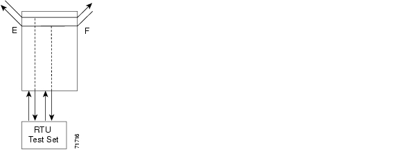
2.2.8 Test Access Configurations
Figure 2-3 Single Node View (Node 1)
Example 2-13 ED-STS1::STS-1-1:90:::TACC=1:;
This command changes STS1 and STS2 on Slot 1 to a TAP. The <CTAG> is 90. Sets the TAP number
to 1.Example 2-14 CONN-TACC-STS1::<AID for E or F depending on MD>:91::TAP-1:MONE
This command connects the <AID> to the TACC defined by TAP 1 on the E side. <CTAG> is 91.
Note
Note
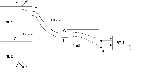
Figure 2-4 Multinode View (MONE Example)
On NE3:
Example 2-15 ENT-CRS-STS1::<AID I-G>:100::2WAY; A connection, not a TAP. CTAG is 100.
ENT-CRS-STS1::<AID J-H>:101::2WAY; Second connection, not a TAP.On NE1:
Assuming the path from A to B is already entered; the A and B points in the diagram refer to entry and exit points on the node or different cards. The E/F designators refer to the two 2-way connections from NE3.
Example 2-16 ED-STS1::STS-1-1:TACC=4; Creates TAP with STS-1-1 and STS-1-2 through NE1. TAP number assigned is 4.
Example 2-17 CONN-TACC-STS1::<AID A or B>:102::4:<MD> Connects TAP 4 to the circuit.
Note
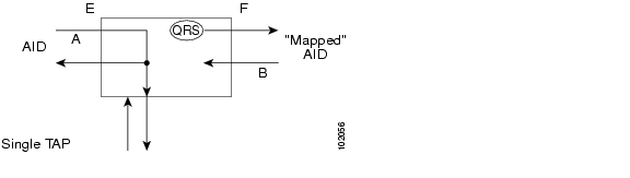
2.2.9 Test Access Mode Definitions
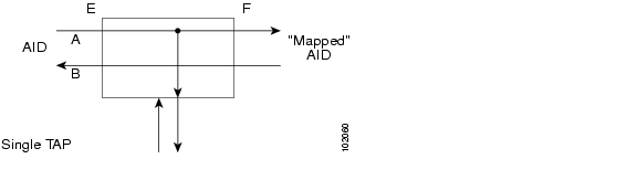
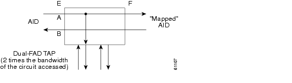
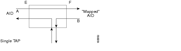
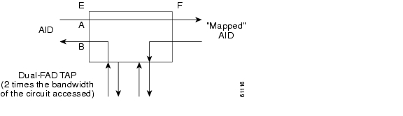
The following diagrams show what the different test access modes <MD> refer to. Figure 2-5 shows a circuit with no access (dual FAD TAP) and Figure 2-6 shows a circuit with no access (single FAD TAP), followed by all the modes. The QRS can be generated by an outside source, for example, the empty connection of the BRTU.
MONE, MONF, and MONEF access modes are non-service effecting and can be applied to an IS (in service) port state.
LOOPE, LOOPF, SPLTE, SPLTF, SPLTEF, SPLTA, SPLTB, and SPLTAB access modes are intrusive and can be applied only to a circuit/port that is in the OOS_MT (out of service, maintenance) port state. The NE will change the state of the circuit under test to OOS_MT during the period of TACC and restore it to the original state when the connection between the TAP and the circuit is dropped.
Figure 2-5 Circuit With No Access (Dual FAD TAP)
Figure 2-6 Circuit With No Access (Single FAD TAP)
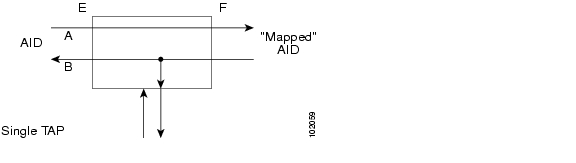
2.2.9.1 MONE
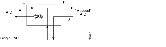
Monitor E (MONE) indicates a monitor connection provided from the facility access digroup (FAD) to the A transmission path of the accessed circuit ( Figure 2-7 and Figure 2-8). This is a non-intrusive mode.
Figure 2-7 MONE Access Single TAP
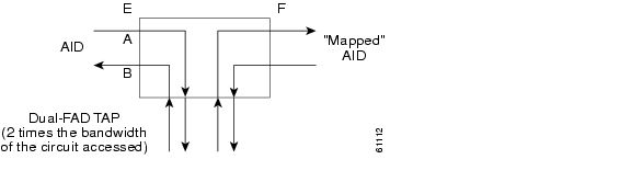
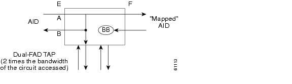
Figure 2-8 MONE Access Dual TAP
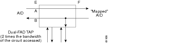
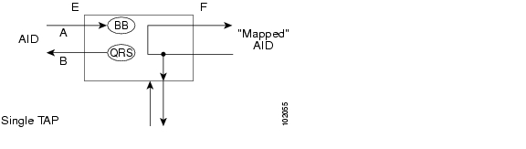
2.2.9.2 MONF
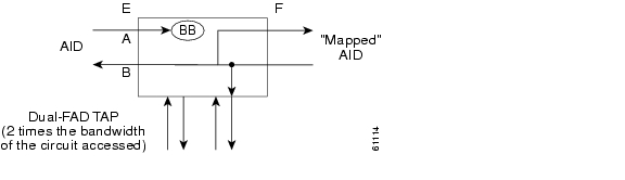
Monitor F (MONF) indicates that the FAD is providing a monitor connection to the B transmission path of the accessed circuit ( Figure 2-9 and Figure 2-10). This is a non-intrusive mode.
Figure 2-9 MONF Access Single TAP
Figure 2-10 MONF Access Dual TAP
Note
2.2.9.3 MONEF
Monitor EF (MONEF) is a monitor connection provided from the FAD1 (odd pair) to a DFAD, to the A transmission path and from FAD2 (even pair) of the same DFAD, to the B transmission path of the accessed circuit. This is a non-intrusive mode ( Figure 2-11).
MONEF for T3 (DS3 HCDS) indicates that the odd pair of a FAP is providing a monitor connection to the A transmission path and from the even pair of a facility access path (FAP) to the B transmission path of the accessed circuit.
Figure 2-11 MONEF Access Dual TAP
2.2.9.4 SPLTE
Split E (SPLTE) splits both the A and B paths and connects the E side of the accessed circuit to the FAD ( Figure 2-12 and Figure 2-13).
Note
Figure 2-12 SPLTE Access Single TAP
Figure 2-13 SPLTE Access Dual TAP
2.2.9.5 SPLTF
Split F (SPLTF) splits both the A and B paths and connects the F side of the accessed circuit to the FAD ( Figure 2-14 and Figure 2-15).
Note
Figure 2-14 SPLTF Access Single TAP
Figure 2-15 SPLTF Access Dual TAP
2.2.9.6 SPLTEF
Split EF (SPLTEF) for T1 (DS1 HCDS) splits both the A and B paths, connects the E side of the accessed circuit to FAD1 and the dual facility access digroup (DFAD) pair, and connects the F side to the FAD2 of the same DFAD pair ( Figure 2-16).
SPLTEF for T3 (DS3 HCDS) splits both the A and B paths and connects the E side of the accessed circuit to the odd pair of the FAP and the F side to the even pair of the FAP.
Figure 2-16 SPLTEF Access Dual TAP
2.2.9.7 LOOPE
Loop E (LOOPE) splits both the A and B paths, connects the incoming line from the E direction to the outgoing line in the E direction, and connects this looped configuration to the FAD ( Figure 2-17 and Figure 2-18). Loop E and F modes are basically identical to the SPLT E and F modes except that the outgoing signal is the incoming signal and not the signal from the remote test unit (RTU).
Note
Figure 2-17 LOOPE Access Single TAP
Figure 2-18 LOOPE Access Dual TAP
2.2.9.8 LOOPF
Loop F (LOOPF) splits both the A and B paths, connects the incoming line from the F direction to the outgoing line in the F direction and connects this looped configuration to the FAD ( Figure 2-19 and Figure 2-20).
Note
Figure 2-19 LOOPF Access Single TAP
Figure 2-20 LOOPF Access Dual TAP
2.2.9.9 SPLTA
Split A (SPLTA) indicates that a connection is provided from both the E and F sides of the A transmission path of the circuit under test to the FAD and split the A transmission path ( Figure 2-21 and Figure 2-22). These modes are similar to the Split E and F modes, except the signals are sent to the RTU, not the NE signal configuration.
Figure 2-21 SPLTA Access Single TAP
Figure 2-22 SPLTA Access Dual TAP
2.2.9.10 SPLTB
Split B (SPLTB) indicates that a connection is provided from both the E and F sides of the B transmission path of the circuit under test to the FAD and split the B transmission path ( Figure 2-23 and Figure 2-24).
Figure 2-23 SPLTB Access Single TAP
Figure 2-24 SPLTB Access Dual TAP
2.2.10 Unmapped AID Test Access Point Connections
The ONS 15454, ONS 15327 and ONS 15600 support connections to unmapped AIDs (unmapped circuits). The TAPs can be connected to an unmapped AID, for example, an AID that does not have a cross-connect on it. The access modes supported are: MONE, SPLTE, and LOOPE.
Example 2-18 creates a TAP on STS-5-1 and STS-5-2.
Example 2-18 ED-STS1::STS-5-1:12:::TACC=1;
DV9-99 1970-01-02 03:16:11
M 12 COMPLD
;Example 2-19 creates an unmapped AID connection with the MONE access mode.
Example 2-19 CONN-TACC-STS1::STS-5-3:12::1:MD=MONE;
DV9-99 1970-01-02 02:51:54
M 12 COMPLD
1
;
Note
Note
Note
Examples:
The following examples ( Example 2-20 through Example 2-24) assume an STS TAP is already created with TAP number = 1.
2.2.10.1 1-Way Circuit
Example 2-20 ENT-CRS-STS1::STS-5-1,STS-5-2:12::1WAY;
DV9-99 1970-07-01 20:29:06
M 12 COMPLD;Example 2-21 CONN-TACC-STS1::STS-5-1:12::1:MD=MONF;
DV9-99 1970-01-01 20:29:47
M 12 DENY
EANS
STS-5-1
/*INCORRECT TAP MODE*/The <AID> specified in the above CONN-TACC command is the source AID for the 1-way circuit. In this case only MONE and SPLTA modes are allowed because there is no B path in the case of a 1-way circuit (see Table 2-2).
Example 2-22 CONN-TACC-STS1::STS-5-1:12::1:MD=MONE;
DV9-99 1970-01-01 20:30:09
M 12 COMPLDExample 2-23 DISC-TACC::1:12;
DV9-99 1970-01-01 20:30:20
M 12 COMPLD
;However if the <AID> specified is the destination AID as shown below, the modes allowed are MONF and SPLTB.
Example 2-24 CONN-TACC-STS1::STS-5-2:12::1:MD=MONF;
DV9-99 1970-01-01 20:30:32
M 12 COMPLD
Note
•
2.2.10.2 2-Way Circuits
For 2-way circuits all the modes are allowed as shown in Table 2-2 and the same applies for UPSR_UPSR and path protection circuit types. In the case of UPSR_UPSR and path protection circuits the working path is connected irrespective of which path is currently active.
2.2.10.3 Unmapped AID
As explained in the "Unmapped AID Test Access Point Connections" section, connections can be made to an <AID> without a cross-connect on it. The modes supported are MONE, SPLTE and LOOPE as shown in Table 2-2.
Note
•
–
–
2.3 TL1 Gateway
This section describes the TL1 Gateway and provides procedures and examples for implementing TL1 Gateway on the ONS 15454, ONS 15327, ONS 15310-CL, and ONS 15600.
2.3.1 Gateway Network Element Topology
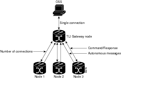
You can issue TL1 commands to multiple nodes via a single connection through the TL1 Gateway. Any node can serve as a Gateway Network Element (GNE), End Network Element (ENE), or Intermediate Network Element (INE). A node becomes a GNE when a TL1 user connects to it and enters a command destined for another node. An ENE is an end node because it processes a TL1 command that is passed to it from another node. An INE is an intermediate node because of topology; it has no special hardware, software, or provisioning.
To implement the TL1 Gateway, use the desired ENE's TID in the ACT-USER command to initiate a session between the GNE and the ENE. Once a session is established you need to enter the ENE's TID in all of the subsequent commands that are destined for the ENE. From the GNE, you can access several remote nodes which become the ENEs. The ENEs are the message destinations or origins. The INE handles the DCC TCP/IP packet exchange.
The GNE Session is the connection that multiplexes TL1 messages between the OSS/craftsperson and the GNE. The GNE demulitplexes incoming operations support system (OSS) TL1 commands and forwards them to the remote ENE. The GNE also multiplexes incoming responses and autonomous messages to the GNE Session. The ENE Session is the connection that exchanges messages between the GNE and the remote ENE. Figure 2-25 shows the GNE topology.
Figure 2-25 Example of a GNE Topology
2.3.2 ONS 15454, ONS 15327 and ONS 15310-CL Gateway
With the TCC2/TCC2P card on an ONS 15454, each GNE can support twenty (19+1) concurrent gateway communication sessions (connections from an OS to the GNE). Nineteen of these sessions are via the LAN (wire-wrap, active TCC2/TCC2P LAN port, or DCC) and the twentieth session is reserved for the active TCC2/TCC2P serial port. With the XTC card on an ONS 15327, or a 15310-CL-CTX card on an ONS 15310-CL each GNE can support six (5+1) concurrent gateway communication sessions. Five of these sessions are via the LAN (wire wrap, active XTC/15310-CL-CTX LAN port or DCC) and the sixth session is reserved for the active XTC/15310-CL-CTX serial port.
Each GNE can support 11 (TCC2/TCC2P) or 6 (XTC/15310-CL-CTX) concurrent communication gateway sessions and up to a maximum of 176 (TCC2/TCC2P) or 96 (XTC/15310-CL-CTX) ENEs/GNE. You can dynamically distribute the ENEs to balance the number of concurrent gateway communication sessions versus the number of NEs on the DCC. The GNE treats the 11 (10+1 for TCC2/TCC2P) or 6 (5+1 for XTC/15310-CL-CTX) concurrent gateway communication sessions and 176 (TCC2/TCC2P) or 96 (XTC/15310-CL-CTX) ENEs/GNE limit as a resource pool ( Table 2-3) and continues to allocate resources until the pool is exhausted (see Table 2-4 for allocation examples). When the pool is exhausted the GNE returns an "All Gateways in Use" message or an "All ENE Connections in Use" message.
2.3.3 ONS 15600 Gateway
Each GNE can support 20 concurrent gateway communication sessions (connections from an OS to the GNE) available via the LAN (CAP, TSC, or DCC). The GNE can support 18 telnet sessions and 2 serial port sessions.
Note
Note
2.3.4 Implementing TL1 Gateway
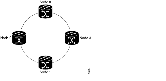
The following procedures demonstrate TL1 Gateway on a four-node ring (without TL1 Gateway in Figure 2-26 and with TL1 Gateway in Figure 2-27), where:
Node 0 is the GNE.
Node 1 is the ENE 1.
Node 2 is the INE 2.
Node 3 is the ENE 3.Figure 2-26 Four-Node Ring Without TL1 Gateway
Figure 2-27 Four-Node Ring With TL1 Gateway
Log Into a Remote ENE
Step 1
Step 2
ACT-USER:NODE1:USERNAME:1234:PASSWORD;
The GNE forwards the login to ENE 1. After successful login, ENE 1 sends a COMPLD response.
Step 3
ACT-USER:NODE3:USERNAME:1234:PASSWORD;
The GNE forwards the login to ENE 3. After successful login, the ENE 3 sends a COMPLD response.
Forward Commands by Specifying the ENE TID (Node 1 or Node 3)
When you are logged into ENE 1 and ENE 3, enter a command and designate a specific TID, as shown in the following example:
RTRV-HDR:NODE1::1;
will retrieve the header of Node 1 and
RTRV-HDR:NODE3::3;
will retrieve the header of Node 3.
Receive Autonomous Messages from the Remote ENE
To receive autonomous messages from the remote ENE, you must log into the remote ENE. When you are logged in, you will begin to receive autonomous messages. The source of the message is identified in the header of the message.
Log Out of a Remote ENE
To disconnect from a remote ENE, you must use the CANC-USER command as follows:
CANC-USER:NODE1:USERNAME:1; will disconnect ENE 1 and
CANC-USER:NODE3:USERNAME:3; will disconnect ENE 3.
The GNE forwards the logout to the remote ENEs. The GNE/ENE TCP session is closed.
2.4 Ring Provisioning
This section provides information and sample procedures for setting up STS or VT circuits over existing path protectionand bidirectional line switch ring (BLSR) configurations using TL1, including:
•
•
•
•
Note
Note
2.4.1 Path Protection Topology
No special configuration of the physical path protection topology is required other than connecting the fibers to the nodes. The east and west paths must exit a node at different ports (to ensure link diversity), but there are no other physical topology restrictions
ONS 15xxx networks give you the option to set up path-protected mesh networks (PPMNs). PPMNs extend the protection scheme of a path protection from the basic ring configuration to the meshed architecture of several interconnected rings. For more information about PPMN, refer to the Cisco Procedure Guide applicable to your platform.
2.4.2 Path Protection Cross-Connections
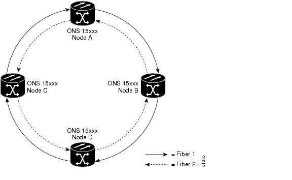
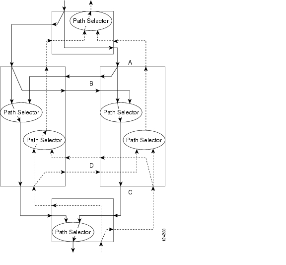
To create a path protection cross-connection using TL1, you only need to designate whether it is a 1-way or 2-way cross-connect, but the access identifier (AID) must be more explicit. For example, to create a 1-way path protection circuit over the network with nodes A, B, C, and D and segments A-B, B-D, A-C, C-D as shown in Figure 2-28, enter the following commands (Node A is the source node and Node D is the destination node):
ENT-CRS-STS1:A:FROM,TO1&TO2:CTAG1::1WAY;
ENT-CRS-STS1:B:FROM,TO:CTAG2::1WAY;
ENT-CRS-STS1:C:FROM,TO:CTAG3::1WAY;
ENT-CRS-STS1:D:FROM1&FROM2,TO:CTAG4::1WAY;Figure 2-28 Network Configured With a 1-Way Path Protection Circuit
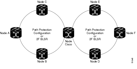
2.4.3 Ring-to-Ring Interconnection
In the following examples, the form "5/1/1" represents "Slot 5, Port 1, STS 1." For VTs add the normal VT Group and VT ID extensions. These examples also assume that the slots/ports have been auto-provisioned (via a plug-in event) and that the ports involved have been placed into the in service state using a port configuration command, for example, ED-OCN.
For the examples in this section, both rings traverse the same node; therefore, only a single cross-connection is required to create the ring-to-ring connection. This is shown in Figure 2-29. The node named "Cisco" is in the nexus.
Figure 2-29 Network Map With Cisco Node Showing Ring-to-Ring Interconnection
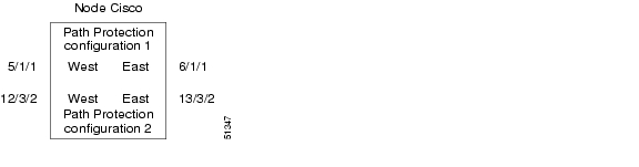
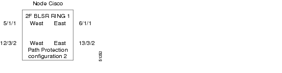
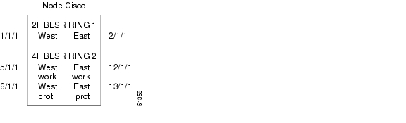
2.4.4 Path Protection to Path Protection Connection Example
Ring 1 = Path Protection
Ring 2 = Path Protection
This example, illustrated in Figure 2-30, uses an OC-3-4 card to feed Ring 2. Ring 1 can have any OC-N trunk card, but the trunk card is most likely a single-port OC-48 or OC-12.
Note
STS 12/3/2 maps to STS-12-8 (((3-1)*3) +2).Figure 2-30 Path Protection-to-Path Protection Connection Specifications Through the Cisco Node
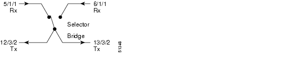
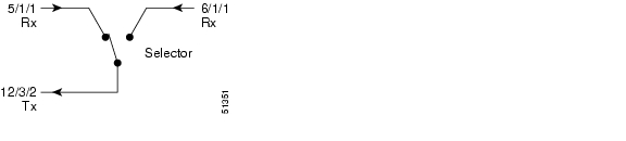
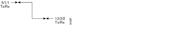
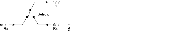
Use the command ENT-CRS-STS1:CISCO:STS-5-1&STS-6-1,STS-12-8&STS-13-8:CTAG1::2WAY; to create a selector between 5/1/1 and 6/1/1 which is bridged to Ring 2 (12/3/2 and 13/3/2), as shown in Figure 2-31.
Figure 2-31 Selector Between 5/1/1 and 6/1/1
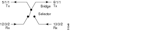
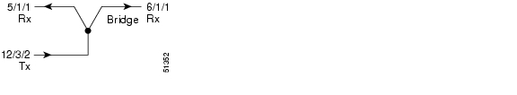
The command also creates a selector between 12/3/2 and 13/3/2 to a bridge to Ring 1 (5/1/1 and 6/1/1), as shown in Figure 2-32.
Figure 2-32 Selector Between 12/3/2 and 13/3/2
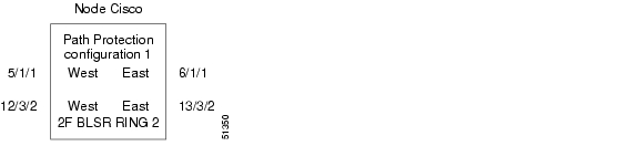
2.4.5 Path Protection to Two-Fiber BLSR Connection Example
Ring 1 = path protection
Ring 2 = Two-fiber BLSR
This example, illustrated in Figure 2-33, uses a path protection end-point with a drop on a two-fiber BLSR and the west span of the two-fiber BLSR (Ring 2) for the active path of the circuit. The example also uses multiport addressing for Ring 2 and is based on a multiport OC12-4 card (this is only important for computing the STS AID for multiport cards) where 13/3/2 = STS-13-26 and where
26 = (((3-1)*12) +2).Figure 2-33 Path Protection to Two-Fiber BLSR
Use the command ENT-CRS-STS1:CISCO:STS-5-1&STS-6-1,STS12-26:CTAG2::2WAY;
to create a selector between 5/1/1 and 6/1/1 which connects to 12/3/2 on Ring 2, as shown in Figure 2-34.Figure 2-34 Selector Between 5/1/1 and 6/1/1
The command also creates a bridge from 12/3/2 to Ring 1 (5/1/1 and 6/1/1), as shown in Figure 2-35.
Figure 2-35 Bridge from 12/3/2 to Ring
In this configuration a two-fiber BLSR switch can automatically reconnect the selector output to the protection path on the east port (12/3/2 assuming OC-12) if necessary.
2.4.6 Two-Fiber BLSR to Path Protection Connection Example
Ring 1 = Two-fiber BLSR
Ring 2 = Path Protection
This example, illustrated in Figure 2-36, uses a path protection end-point with a drop on a two-fiber BLSR and uses the east span of the two-fiber BLSR (Ring 1) for the active path of the circuit. For STS addressing, the path protection is an OC-3 (for example, STS-13-8).
Figure 2-36 Two-Fiber BLSR to Path Protection
Use the ENT-CRS-STS1:CISCO:STS-6-1,STS-12-8&STS-13-8:CTAG3::2WAY;
to create a bridge from 6/1/1 to Ring 2 (12/3/2 and 13/3/2), as shown in Figure 2-37.Figure 2-37 Bridge from 6/1/1 to Ring 2
The command also creates a selector between 12/3/2 and 13/3/2 to Ring 1 (6/1/1) as shown in Figure 2-38.
Figure 2-38 Selector Between 12/3/2 and 13/3/2 to Ring 1
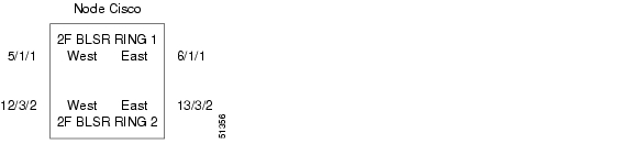
2.4.7 Two-Fiber BLSR to Two-Fiber BLSR Connection Example
Ring 1 = Two-fiber BLSR
Ring 2 = Two-fiber BLSR
All protection for a two-fiber BLSR interconnecting to a two-fiber BLSR is performed at the line level. You can make the connection with a 2-way cross-connect from an STS on the working side of the two-fiber BLSR span of Ring 1 to an STS on the working side of a two-fiber BLSR span on Ring 2. The connections can be east to east, east to west, west to east, and west to west. This example, illustrated in Figure 2-39, uses Ring 1 west to Ring 2 east and assumes an OC-12-4 card in Slots 12 and 13 for subtending to a two-fiber BLSR (Ring 2).
Figure 2-39 Two-Fiber BLSR to Two-Fiber BLSR
Use the ENT-CRS-STS1:CISCO:STS-5-1,STS-13-26:CTAG4::2WAY;
to create a 2-way connection from 5/1/1 to 13/3/2 as shown in Figure 2-40.Figure 2-40 2-Way Connection from 5/1/1 to 13/3/2
2.4.8 Two-Fiber BLSR to Four-Fiber BLSR Connection Example (ONS 15454)
Ring 1 = Two-fiber BLSR
Ring 2 = Four-fiber BLSR
All protection for a two-fiber BLSR interconnecting to a four-fiber BLSR is performed at the line level. You can make the connection with a simple 2-way cross-connect from the appropriate side, east or west, of the two-fiber BLSR to the working fiber of the appropriate side, east or west, of the four-fiber BLSR, as shown in Figure 2-41.
Figure 2-41 Two-Fiber BLSR to Four-Fiber BLSR
Use the command ENT-CRS-STS1:CISCO:STS-1-1,STS-5-1:CTAG5::2WAY;
to create a 2-way connection from 1/1/1 to 5/1/1, as shown in Figure 2-42.Figure 2-42 2-Way Connection from 1/1/1 to 5/1/1
In the event of a failure, the software will automatically switch the traffic to the appropriate line and path.
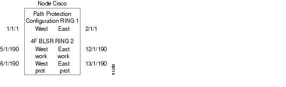
2.4.9 Path Protection to Four-Fiber BLSR Connection Example (ONS 15454)
Ring 1 = Path Protection
Ring 2 = Four-fiber BLSR
This example uses the west span of the four-fiber BLSR (Ring 2) for the active path of the circuit. The example also assumes that the four-fiber BLSR travels over OC-192 spans, as shown in Figure 2-43.
Figure 2-43 Path Protection to Four-Fiber BLSR
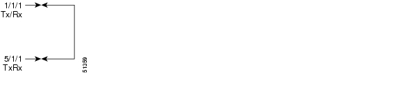
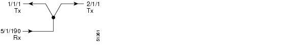
Use the command ENT-CRS-STS1:CISCO:STS-1-1&STS-2-1&STS-5-190:CTAG6::2WAY;
to create a selector between 1/1/1 and 2/1/1 to Ring 2 (5/1/190), as shown in Figure 2-44.Figure 2-44 Selector Between 1/1/1 and 2/1/1 to Ring 2 (5/1/190)
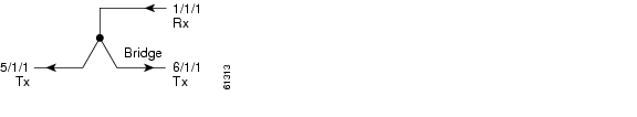
The command also creates a bridge from 5/1/190 to Ring 1 (1/1/1 and 2/1/1), as shown in Figure 2-45.
Figure 2-45 Bridge From 5/1/190 to Ring 1 (1/1/1 and 2/1/1)
2.4.10 1-Way Drop and Continue
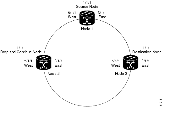
The following examples show how to create a 1-way drop and continue cross-connect. The examples use three nodes (Node 1, Node 2, and Node 3) in a ring configuration ( Figure 2-46). Node 1 is the source node, Node 2 has the drop and continue, and Node 3 is the destination.
Figure 2-46 1-Way Drop and Continue
Figure 2-47 shows a circuit diagram example of the orientation of AIDs associated with the ENT-CRS command used to establish drop and continue connections.
Figure 2-47 Orientation of AIDs Used to Establish Drop and Continue Connections
2.4.11 Node 1 Configuration Example (Source Node)
Issue the command ENT-CRS-STSn::STS-1-1,STS-5-1&STS-6-1:CTAG::1WAY; command on Node 1.
Figure 2-48 Bridge from 1/1/1 to 5/1/1 and 6/1/1
2.4.12 Node 2 Configuration Example (Drop and Continue Node)
Issue the command ENT-CRS-STSn::STS-5-1&STS-6-1,STS-1-1:CTAG::1WAYDC; on Node 2.
Figure 2-49 Selector Between 5/1/1 and 6/1/1 to 1/1/1
2.4.13 Node 3 Configuration Example (Destination Node)
Issue the command ENT-CRS-STSn::STS-5-1&STS-6-1,STS-1-1:CTAG::1WAY; on Node 3.
Figure 2-50 Selector Between 5/1/1 and 6/1/1 to 1/1/1
2.5 PCA Provisioning
You can provision or retrieve protection channel access (PCA) cross-connections on two-fiber and four-fiber BLSR topologies at these supported OC rates: OC-12 (two-fiber only), OC-48, and OC-192. The traffic on the protection channel is referred to as extra-traffic and has the lowest priority level. Extra traffic will be preempted by any working traffic that requires the use of the protection channel.
In a two-fiber BLSR the extra traffic is provisioned on the upper half of the bandwidth path. In a four-fiber BLSR the extra traffic is provisioned on the protect fiber. The PCA provisioning feature allows you to establish the PCA cross-connection on the protection path of the two-fiber BLSR and protection channel of the four-fiber BLSR only when the query is an explicit request.
There are two PCA connection types: 1WAYPCA and 2WAYPCA. The PCA cross-connection is provisioned only when the user provides an explicit request using the ENT-CRS-STSp/VT1 commands. If the cross-connection is a PCA cross-connection, either 1WAYPCA or 2WAYPCA is shown in the CCT field of the RTRV-CRS-STSp/VT1 command output.
1WAYPCA and 2WAYPCA are only used in the TL1 user interface to provide usability and visibility for the user to specify a PCA cross-connection type in the TL1 cross-connection commands.
Note
•
•
•
2.5.1 Provision a PCA Cross-Connection
Input format for provisioning a PCA cross-connection:
Example 2-25 ENT-CRS-<PATH>:[<TID>]:<FROM>,<TO>:<CTAG>::[<CCT>][::];
<PATH>::={STS_PATH | VT1}
[<CCT>]::={1WAY, 1WAYDC, 1WAYEN, 2WAY, 1WAYPCA, 2WAYPCA}, it defaults to 2WAY.
{STS_PATH}::={STS1 | STS3C | STS6C | STS9C | STS12C | STS24C | STS48C | STS192C}STS= all the STS bandwidth cross-connections.
VT1=VT1_5 cross-connection.
Input example of provisioning an STS3C PCA cross-connection:
Example 2-26 ENT-CRS-STS3C::STS-1-1,STS-2-1:123::2WAYPCA;
Note
Note
2.5.2 Retrieve a PCA Cross-Connection
Input Format for retrieving a PCA cross-connection:
Example 2-27 RTRV-CRS-[<PATH>]:[<TID>]:<AID>:<CTAG>[::::];<PATH>::=
{STS_PATH | VT1 | STS}If PATH is STS, it will retrieve all the STS cross-connections based on the queried AIDs.
<AID>={FacilityAIDs, STSAIDs, VTAIDs, ALL}
Output format of the PCA STSp cross-connection retrieval command:
Example 2-28 "<FROM>,<TO>:2WAYPCA,STS3C"
Output format of the PCA VT cross-connection retrieval command:
Example 2-29 "<FROM>,<TO>:2WAYPCA"
2.6 FTP Software Download
Note
The file transfer protocol (FTP) software download feature downloads a software package to the inactive flash partition residing on either the TCC2/TCC2P, XTC, 15310-CL-CTX, or TSC card. FTP software download provides for simplex and duplex TCC2/TCC2P, XTC, 15310-CL-CTX, or TSC card downloads, success and failure status, and in-progress status at 20% increments.
2.6.1 COPY-RFILE
The COPY-RFILE command downloads a new software package from the location specified by the FTP URL into the inactive flash partition residing on either the TCC2/TCC2P, XTC,15310-CL-CTX or TSC card. COPY-RFILE can also be used to backup and restore the database file.
Note
Input format:
Example 2-30 COPY-RFILE:[<TID>]:[<SRC>]:<CTAG>::TYPE=<XFERTYPE>,[SRC=<SRC1>,]
[DEST=<DEST>,][OVWRT=<OVWRT>];where:
•
•
•
/PACKAGE_PATH[:TYPE=I]"where:
–
–
–
–
–
In a firewall environment the hostname should be replaced with a list of IP addresses each separated by a "@" character. The first IP address should be for the computer where the package file is stored. Subsequent IP addresses are for firewall computers moving outward toward the edge of the network until the final IP address listed is the computer that outside users use to first access the network.
For example, if your topology is:
"FTPHOST <-> GNE3 <->GNE2 <-> GNE1 <-> ENE"
the FTP URL is:
FTP://FTP_USER:FTP_PASSWORD@FTP_HOST_IP@GNE3@GNE2@GNE1/
PACKAGE_PATHSRC1 is a String
–
–
Note
•
2.6.2 APPLY
The APPLY command can activate or revert software depending on the version of software loaded on the active and protect flash. An error is returned if the node is attempting to activate to an older software load or trying to revert to a newer software load. If this command is successful the appropriate flash is selected and the TCC2/TCC2P, XTC, 15310-CL-CTX, or TSC card will reboot.
Input format:
Example 2-31 APPLY:[<TID>]::<CTAG>[::<MEM_SW_TYPE>]:
where:
•
2.6.3 REPT EVT FXFR
REPT EVT FXFR is an autonomous message used to report the start, completion, and completed percentage status of the FTP software download. REPT EVT FXFR also reports any failure during the software upgrade including invalid package, invalid path, invalid userid/password, and loss of network connection.
Note:
1.
2.
Output format:
Example 2-32 SID DATE TIME
A ATAG REPT EVT FXFR
"<FILENAME>,<FXFR_STATUS>,[<FXFR_RSLT>],[<BYTES_XFRD>]"
;where:
•
•
•
•
2.6.4 Downloading New Software
The following procedure downloads new software to the TCC2/TCC2P, XTC, 15310-CL-CTX or TSC card using TL1.
Download New Software
Note
Step 1
Step 2
Step 3
Step 4
Input example:
Example 2-33 RTRV-NE-GEN:::1;
Output example:
Example 2-34 VA454-94 1970-01-06 22:22:12
M 1 COMPLD
"IPADDR=10.82.87.94,IPMASK=255.255.255.224,DEFRTR=10.82.86.1,
ETHIPADDR=10.82.87.94,ETHIPMASK=255.255.255.224,NAME=VA454-94,
SWER=3.40.00,LOAD=03.40-002G-14.21,PROTSWVER=4.00.00,
PROTLOAD=04.00-X02G-25.07,DEFDESC=\"FACTORY DEFAULTS\""
;Step 5
In the following example the package is located in "/%2FUSR/CET/VINTARA" in the host 10.77.22.199. The userid and passwords are TL1 and CISCO454. The directory path of the package is similar to what you will see during an FTP session.
Example 2-35 COPY-RFILE::RFILE-
PKG:CTAG::TYPE=SWDL,SRC="FTP://TL1:CISCO454@10.77.29.199
/%2FUSR/CET/VINTARA/15454-0340-X02E-2804.PKG";
DEV208 1970-01-10 11:51:57
M CTAG COMPLD
;Step 6
•
•
•
•
•
•
•
•
•
Example 2-36 DEV208 1970-01-10 11:52:02
A 2816.2816 REPT EVT EQPT
"SLOT-11:SFTWDOWN-FAIL,TC,,,,,,,:\"SOFTWARE DOWNLOAD FAILED\",TCC
;Step 7
Example 2-37 DEV208 1970-01-10 11:52:15
A 2818,2818 REPT EVT FXFR
"ACTIVE START"
;Step 8
Example 2-38 DEV208 1970-01--10 11:52:15
* 2817.2817 REPT ALM EQPT
"SLOT-7:MN,SFTWDOWN,NSA,,,,:\"SOFTWARE DOWNLOAD IN PROGRESS\",TCC"
;Use the in-progress status at any time during the software download to verify the RTRV-NE-GEN command.
Example 2-39 RTRV-NE-GEN
VA454-94 1970-01-06 22:22;12
M 1 COMPLD
"IPADDR=10.82.87.94,IPMASK=255.255.255.224,DEFRTR=10.82.86.1,
ETHIPADDR=10.82.87.94,EHTIPMASK=255.255.255.224,NAME=VA454-94,
SWVER=3.40.00,LOAD=03.40-002G-14-21,PROTSWVER=NONE,
PROTLOAD=DOWNLOADINPROGRESS,DEFDESC=\:FACTORY DEFAULTS\""
;Step 9
Example 2-40 DEV208 1970-01-10 11:53:12
A 2820,2820 REPT EVT FXFR
"ACTIVE,IP,,20"
;
DEV208 1970-01-10 11:53:12
A 2820,2820 REPT EVT FXFR
"ACTIVE,IP,,40"
;
DEV208 1970-01-10 11:53:12
A 2820,2820 REPT EVT FXFR
"ACTIVE,IP,,60"
;
DEV208 1970-01-10 11:53:12
A 2820,2820 REPT EVT FXFR
"ACTIVE,IP,,80"
;Step 10
Example 2-41 RTRV-NE-GEN:::1;
VA454-94 1970-01-06 22:22:12
M 1 COMPLD
"IPADDR=10.82.87.94,IPMASK=255.255.255.224,DEFRTR=10.82.86.1,
ETHIPADDR=10.82.87.94,EHTIPMASK=255.255.254.0,NAME=VA454-94,
SWVER=3.40.00,LOAD=03.40-002G-14-21,PROTSWVER=4.00.00,
PROTLOAD=03.40-X02E-28.04,DEFDESC=\:FACTORY DEFAULTS\""
;Step 11
Example 2-42 DEV208 1970-01-10 12:01:16
A 2825,2825 REPT EVT FXFR
"ACTIVE,COMPLD,SUCCESS"
;Step 12
Example 2-43 DEV208 1970-01-10 11:52:15
* 2826,2817 REPT ALM EQPT
"SLOT-7:CL,SFTWDOWN,NSA,,,,:\"SOFTWARE DOWNLOAD IN PROGRESS\",TCC"
;2.6.5 Activating New Software
After the software is successfully downloaded, the new software which resides in the protect load must be activated to run on the NE. The APPLY command can be used to activate and revert depending on the version of the protect software and the newly downloaded software (see the "APPLY" section for correct APPLY syntax).
Activate New Software
Step 1
Example 2-44 APPLY::1::ACT;
DEV208 1970-01-10 13:40:53
M 1 COMPLD
;An error is reported if a revert is attempted with a newer protect software.
Step 2
Example 2-45 CANC-USER::CISCO15:1;
VA454-94 1970-01-07 01:18:18
M 1 COMPLD
;After a successful completion of the APPLY command the NE will reboot and the TL1 session will disconnect. When the NE comes up after the reboot it will be running the new software. Traffic switches are possible during activation.
2.6.6 Remote Software Download/Activation Using the GNE
In a network with SDCC-connected ONS 15454, ONS 15327 and ONS 15310-CLs remote download and activation are possible using the GNE/ENE feature supported in TL1. The GNE must be connected by a LAN and the remaining ENEs can download the new software package through fiber from the GNE.
For remote software downloading, complete the steps in the "Download New Software" procedure and the "Activate New Software" procedure, but ensure that the TID in each command is filled with the ENE node name.
Each GNE can support 20 (TCC2/TCC2P) or 6 (XTC or 15310-CL-CTX) concurrent communication gateway sessions and up to a maximum of 176 (TCC2/TCC2P) or 96 (XTC or 15310-CL-CTX) ENEs/GNE. For more information on TL1 Gateway, see the "TL1 Gateway" section.
Example 2-46 ACT-USER:NODE1:CISCO15:1;
ACT-USER:NODE2:CISCO15:1;
ACT-USER:NODE3:CISCO15:1;
ACT-USER:NODE4:CISCO15:1;
ACT-USER:NODE5:CISCO15:1;Five simultaneous software downloads can be initiated using the COPY-RFILE command with appropriate TIDs. All downloads will be independent of each other and download speeds might differ.
Example 2-47 COPY-RFILE:NODE1:RFILE-PKG:CTAG::TYPE=SWDL,SRC="FTP://TL1:
CISCO454@10.77.29.199/USR/CET/VINTARA/15454-0340-X02E-2804.PKG";
COPY-RFILE:NODE2:RFILE-PKG...
COPY-RFILE:NODE3:RFILE-PKG...
COPY-RFILE:NODE4:RFILE-PKG...
COPY-RFILE:NODE5:RFILE-PKG...Individual REPT EVT FXFR messages can be isolated using the node names. RTRV-NE-GEN also requires the individual node names entered in the TID to see a specific download status.
You can activate the software on all of the nodes using the GNE node.
Note
Example 2-48 APPLY:NODE1::1::ACT;
APPLY:NODE2::1::ACT;
APPLY:NODE3::1::ACT;
APPLY:NODE4::1::ACT;
APPLY:NODE5::1::ACT;2.7 Scheduled PM Report
The scheduled performance monitoring (PM) report is a feature that extends the capability of PM reporting for the Cisco ONS 15454, ONS 15327, ONS 15310-CL and ONS 15600. With scheduled PM report the system automatically and periodically generates the PM report of any specified facility or cross-connection.
Note
•
•
•
•
2.7.1 Create a PM Schedule and Receive an Autonomous PM Report
1.
2.
2.7.2 Manage PM Schedules
1.
2.
Note
3.
Note
2.7.3 Enable or Disable a TL1 Session to Receive Autonomous PM Reports
1.
Note
2.
2.8 Bridge and Roll
Cisco ONS 15454, ONS 15327, ONS 15600, ONS 15310-CL
Bridge and Roll functionality allows live traffic to be moved (rolled) from one entity to another. This section provides information and sample procedures for single-rolling, dual-rolling and protection rolling for one-way or two-way circuits using TL1 commands, including:
•
•
•
There are two roll modes:
•
•
Caution
Caution
Note
2.8.1 Restrictions
The following restrictions apply for bridge and roll using TL1 in this release:
1.
2.
3.
4.
5.
6.
7.
8.
9.
10.
11.
12.
13.
14.
15.
Note
16.
Note
17.
Note
18.
The following restrictions apply for bridge and roll using TL1 VCAT in this release:
1.
2.
The following restrictions apply for bridge and roll using TL1 common fiber-routed VCAT circuits in this release:
3.
4.
2.8.2 Bridge and Roll TL1 Commands
The following commands are used for bridge and roll:
•
This command deletes or completes an attempted rolling operation. This command supports line level rolling/bulk rolling and cannot be used for path-level rolling. The rolls that are created using the ENT-BULKROLL-<OCN_TYPE> command can be deleted using the DLT-BULKROLL-<OCN_TYPE> command.
•
This command deletes an attempted rolling operation or completes an attempted rolling operation.
•
This command edits information about rolling traffic from one endpoint to another without interrupting service. This command can use the CMDMDE option to force a valid signal. The only parameter that can be edited is CMDMDE. The time slots cannot be edited. This commands supports line-level rolling/bulk rolling and cannot be used for path-level rolling.
•
This command edits information about rolling traffic from one endpoint to another without interrupting service. This command can use the CMDMDE option to force a valid signal. The only parameter that can be edited is CMDMDE. The time slots cannot be edited.
•
This command enters information about rolling traffic from one endpoint to another without interrupting service. This commands supports line level/bulk rolling and cannot be used for single path-level rolling.
•
This command enters information about rolling traffic from one endpoint to another without interrupting service. This command supports STS and VT path-level rolling only.
•
This command retrieves roll data parameters. This command supports line-level rolling/bulk rolling and cannot be used for path-level rolling.
•
This command retrieves roll data parameters.
2.8.3 2-Way Circuit Single Roll and Dual Roll Procedures
Single roll operation moves either the source or destination of a circuit to a new endpoint:
•
•
In single roll operation, you only choose one roll point during the process.
Dual roll operation reroutes a segment between two roll points of a circuit. The new route can be:
•
•
•
2.8.3.1 Create a 2-Way Circuit Single Roll or Dual Roll
To create a 2-way circuit single roll or dual roll, enter the ENT-ROLL-<MOD_PATH> command or the ENT-BULKROLL-<OCN_TYPE> command depending on the type of roll you want to perform.
Input Formats:
•
RTO=<RTO>,RMODE=<RMODE>,[CMDMDE=<CMDMDE>];•
[RFROMSTART=<RFROMSTART>],[RFROMEND=<RFROMEND>],RMODE=<RMODE>,
[CMDMDE=<CMDMDE>];
Step 1
•
Input Example:
ENT-ROLL-STS1:CISCO:STS-1-1-1,STS-2-1-1:1:::RFROM=STS-2-1-1,
RTO=STS-3-1-1,RMODE=AUTO,CMDMDE=FRCD;•
Input Example:
ENT-ROLL-STS1:CISCO:STS-1-1-1,STS-2-1-1:1:::RFROM=STS-2-1-1,
RTO=STS-3-1-1,RMODE=MAN,CMDMDE=FRCD;•
Input Example:
ENT-BULKROLL-OC48:CISCO:FAC-5-1:123:::RFROMSTART=STS-5-1-1,
RTOSTART=STS-6-1-1,RMODE=AUTO,CMDMDE=FRCD;This command will roll all the STS and VT paths to a facility on Slot 6 with the same STS as shown in Table 2-5.
•
Input Example:
ENT-BULKROLL-OC48:CISCO:FAC-5-1:123:::RFROMSTART=STS-5-1-1,
RTOSTART=STS-6-1-1,RFROMEND=STS-5-1-4,RMODE=AUTO,CMDMDE=FRCD;This command will roll the paths shown in Table 2-6.
Step 2
Input Format:
RTRV-BULKROLL-<OCN_TYPE>:[<TID>]:<SRC>:<CTAG>;
Input Example:
RTRV-BULKROLL-OC12:CISCO:FAC-3-1:1;
2.8.4 1-Way Circuit Single Roll and Dual Roll Procedures
Single roll operation moves either the source or destination of a circuit to a new endpoint:
•
•
In single roll operation you only choose one roll point during the process.
Dual roll operation reroutes a segment between two roll points of a circuit. The new route can be:
•
•
•
2.8.4.1 Create a 1-Way Circuit Single Roll
To create a 1-way circuit single roll, enter the ENT-ROLL-<MOD_PATH> command or the ENT-BULKROLL-<OCN_TYPE> command depending on the type of roll you want to perform.
Input Formats:
•
RTO=<RTO>,RMODE=<RMODE>,[CMDMDE=<CMDMDE>];
Note
•
[RFROMSTART=<RFROMSTART>],[RFROMEND=<RFROMEND>],RMODE=<RMODE>,
[CMDMDE=<CMDMDE>];
Step 1
•
Input Example:
ENT-ROLL-STS1:CISCO:STS-1-1-1,STS-2-1-1:1:::RFROM=STS-2-1-1,
RTO=STS-3-1-1,RMODE=AUTO,CMDMDE=FRCD;•
Input Example:
ENT-ROLL-STS1:CISCO:STS-1-1-1,STS-2-1-1:1:::RFROM=STS-2-1-1,
RTO=STS-3-1-1,RMODE=MAN,CMDMDE=FRCD;•
Input Example:
ENT-ROLL-STS1:CISCO:STS-1-1-1,STS-2-1-1:1:::RFROM=STS-2-1-1,
RTO=STS-3-1-1,RMODE=AUTO,CMDMDE=FRCD;This command will roll all the STS and VT paths to a facility on Slot 6 with the same STS as shown in Table 2-7 below:
•
Input Example:
ENT-BULKROLL-OC48:CISCO:FAC-5-1:123:::RTOSTART=STS-6-1-1,
RFROMSTART=STS-5-1-1,RFROMEND=STS-5-1-4,RMODE=AUTO,CMDMDE=FRCD;This command will roll the paths shown in Table 2-8 as follows:
Step 2
Input Format:
RTRV-BULKROLL-<OCN_TYPE>:[<TID>]:<SRC>:<CTAG>;
Input Example:
RTRV-BULKROLL-OC12:CISCO:FAC-3-1:1;
2.8.4.2 Create a 1-Way Circuit Dual Roll
In this procedure, both the source and destination nodes are rolled. There are two types of dual rolls:
•
•
Step 1
Step 2
2.8.5 Protection Rolling Procedures
To perform protection rolls, follow the procedures in the "2-Way Circuit Single Roll and Dual Roll Procedures" section and the "1-Way Circuit Single Roll and Dual Roll Procedures" section.
Note
Table 2-9 shows what kind of protection rolls are supported from one domain to another. X indicates the roll is allowed.
Table 2-9 Supported Protection Rolls
X
X
X
X
X
X
X
X
X
X
X
X
X
X
X
X
X
2.9 1:N Low-Density to 1:N High-Density Upgrade
(Cisco ONS 15454)
The following procedure describes the upgrade of DS1 electrical cards to DS1/E1-56 high-density cards using TL1. This procedure can be performed only when logged in as a Superuser.
Note
•
•
–
–
•
Step 1
Input Format:
CHG-EQPT:[<TID>]:<AID>:<CTAG>::<NEW_EQPT_TYPE>;
Input Example:
CHG-EQPT::SLOT-15:123::DS1-E1-56;
Step 2
Step 3
Input Format:
SW-TOPROTN-EQPT:[<TID>]:<AID>:<CTAG>::[<MODE>],[<DIRN>];
Input Example:
SW-TOPROTN-EQPT::SLOT-16:123::FRCD,SLOT-15,BTH;
Step 4
Input Format:
CHG-EQPT:[<TID>]:<AID>:<CTAG>::<NEW_EQPT_TYPE>;
Input Example:
CHG-EQPT::SLOT-16:123::DS1-E1-56;
Step 5
Step 6
Input Format:
SW-TOWKG-EQPT:[<TID>]:<AID>:<CTAG>::[<MODE>],[<DIRN>];
Input Example:
SW-TOWKG-EQPT::SLOT-16:123::FRCD,BTH;
Step 7
2.10 Remote Monitoring-Managed PMs
This section describes the retrieval, threshold setting, threshold crossing alerts (TCAs) and scheduled performance monitoring (PM) reporting for all the remote monitoring (RMON)-managed PM data in the Cisco ONS 15454, ONS 15327, ONS 15310-CL and ONS 15600.
Note
The cards that support RMON PMs include: G1K-4, ML1000-2/ML100T-12, FC_MR-4, ASAP-4, MXP_MR_2.5G/MXPP_MR_2.5G, and ML-100T-8/CE-100T-8. The PM types for these cards include Ethernet statistic types defined in standard SNMP/RMON MIB, and also include other statistic types managed by RMON, for example, the Fibre Channel statistic types.
When creating an RMON threshold, there are two threshold values that need to be specified. The first threshold is the rising threshold and the other is the falling threshold. There are other parameters that need to be specified when creating the RMON threshold, for example, the startup type and the sample type.
Note
The current bucket is not defined by the RMON. RMON-managed PM only shows the history data of the PMs and the data accumulated since the last time the counters are cleared (RAW-DATA).
In the RMON TCA, the accumulation time period is not the predefined PM bucket accumulation time, such as 15-MIN or 1-DAY. It can be any integer (any time greater than 10 seconds) that is defined when creating the RMON threshold.
Note
2.10.1 RTRV-PM-<MOD2>
The RTRV-PM-<MOD2> command retrieves the RMON-managed PMs.
The TL1 modifiers FSTE/GIGE/POS are used to retrieve the RMON-managed Ethernet PM, if the Ethernet port is a FSTE/GIGE/POS port type. The FC modifier retrieves the RMON-managed Fibre Channel PM.
There are three accumulation time periods for RMON statistics: 1-MIN, 1-HR, and RAW-DATA. For RMON-managed PMs, only history PM buckets and RAW-DATA are supported and there is no current bucket defined for RMON-managed PMs. When RAW-DATA is specified in the input of RTRV-PM, the date and time specified in the input will be ignored. The mondate and montime in the output will be the last time the counters were cleared. RAW-DATA will be the default TMPER value for RMON-managed PM retrieval.
Because RMON PM only supports the history data if the accumulation time period is 1-MIN, 15-MIN, 1-HR, or 1-DAY, you must specify the correct history PM bucket for the RTRV-PM command to succeed.
When retrieving PM, if an unsupported montype is specified, an error message will be returned.
Currently there is no support of LOCN (location) and DIRN (direction) for RMON-managed data statistics.
Input FormatRTRV-PM-<MOD2>:[<TID>]:<AID>:<CTAG>::[<MONTYPE>],[<MONLEV>],[<lSTM>],
[<DIRECTION>],[<TMPER>],[<DATE>],[<TIME>];Input ExampleRTRV-PM-GIGE:TID:FAC-2-1:123::ETHERSTATSOCTETS,,,,1-MIN,04-11,12-45;
RTRV-PM-GIGE:TID:FAC-2-1:123::,,,,RAW-DATA;
Output FormatSID DATE TIME
M CTAG COMPLD
"<AID>,[<AIDTYPE>]:<MONTYPE>,<MONVAL>,[<VLDTY>],[<LOCN>],
[<DIRECTION>],[<TMPER>],[<MONDAT>],[<MONTM>]"
;Output ExampleTID-000 1998-06-20 14:30:00
M 001 COMPLD
"FAC-2-1,GIGE:etherStatsOctets,21,COMPL,,,1-MIN,04-11,12-45"
;Table 2-10 shows the error messages associated with the RTRV-PM-<MOD2> command.
2.10.2 ENT-RMONTH-<MOD2_RMON>
The ENT-RMONTH-<MOD2_RMON> command creates a threshold type (an entry in the RMON alarm table) for an RMON statistic, for the RMON-managed PMs. An event (TCA) is generated and reported when the threshold is crossed in the appropriate direction during the sampled time period.
More than one threshold can be created by using different parameters (rising/falling threshold), for each montype.
This command applies to G1000, GIGE, FSTE, POS, and FC data objects.
Input FormatENT-RMONTH-<MOD2>:[<TID>]:<AID>:<CTAG>::<MONTYPE>,,,,<INTVL>:RISE=<RISE>,
FALL=<FALL>,[SAMPLE=<SAMPLE>,][STARTUP=<STARTUP >][:];Input ExampleThe following example creates an entry in the RMON threshold table for the etherStatsOctets statistic type with an interval equal to 100 seconds, rising threshold of 1000, falling threshold of 100, DELTA sampling type and the startup type of RISING-OR-LTING.
ENT-RMONTH-GIGE:CISCO:FAC-2-1:123::ETHERSTATSOCTETS,,,,100:RISE=1000,
FALL=100,SAMPLE=DELTA,STARTUP=RISING-OR-LTING;Table 2-11 shows the error messages associated with the ENT-RMONTH-<MOD2_RMON> command.
2.10.3 DLT-RMONTH-<MOD2_RMON>
The DLT-RMONTH-<MOD2_RMON> command deletes a threshold type (an entry in the RMON alarm table) created for a montype (RMON statistic type). Because there can be multiple thresholds created for a particular montype, you must specify all the necessary parameters for the threshold, in order to identify the particular threshold to be deleted.
This command applies to G1000, GIGE, FSTE, POS, and FC data objects.
Input FormatDLT-RMONTH-<MOD2>:[<TID>]:<AID>:<CTAG>::<MONTYPE>,,,,<INTVL>:RISE=<RISE>,
FALL=<FALL>,[SAMPLE=<SAMPLE>,][STARTUP=<STARTUP>][:];Input ExampleThe following example deletes an entry in the RMON threshold table for the etherStatsOctets statistic type, with an interval equal to 100 seconds, rising threshold of 1000, falling threshold of 100, DELTA sampling type, and the startup type of BOTH.
DLT-RMONTH-GIGE:CISCO:FAC-2-1:123::ETHERSTATSOCTETS,,,,100:RISE=1000,FALL=100,
SAMPLE=DELTA,STARTUP=BOTH;Table 2-12 shows the error messages associated with the DLT-RMONTH-<MOD2_RMON> command.
2.10.4 RTRV-RMONTH-<MOD2_RMON>
The RTRV-RMONTH-<MOD2_RMON> command retrieves the thresholds defined in the RMON alarm table.
Input FormatRTRV-RMONTH-<MOD2>:[<TID>]:<AID>:<CTAG>::[<MONTYPE>]>,,,,
[<INTVL>]:[RISE=<RISE>,][FALL=<FALL>,][SAMPLE=<SAMPLE>,][STARTUP=<STARTUP>];Input ExampleThe following example retrieves all the thresholds defined in the RMON threshold table for the etherStatsOctets statistics type.
RTRV-RMONTH-GIGE:TID:FAC-2-1:123::ETHERSTATSOCTETS;
The following example retrieves all the thresholds with the DELTA sampling type, RISING startup type, for the etherStatsOctets statistics type, defined in the RMON threshold table.
RTRV-RMONTH-GIGE:CISCO:FAC-2-1:123::ETHERSTATSOCTETS:SAMPLE=DELTA,
STARTUP=RISING;Output FormatSID DATE TIME
M CTAG COMPLD
"<AID>,[<AIDTYPE>]:<MONTYPE>,,,,[<INTVL>]:INDEX=<INDEX>,RISE=<RISE>,
FALL=<FALL>,SAMPLE=<SAMPLE>,STARTUP=<STARTUP>"
;Output ExampleTID-000 1998-06-20 14:30:00
M 001 COMPLD
"FAC-2-1,GIGE:ETHERSTATSOCTETS,,,,100:INDEX=2,RISE=1000,FALL=100,
SAMPLE=DELTA,STARTUP=RISING"
;Table 2-13 shows the error messages associated with the DLT-RMONTH-<MOD2_RMON> command.
2.10.5 REPT EVT <MOD2ALM> for Threshold Crossing Events
The REPT EVT <MOD2ALM> autonomous message reports the threshold crossing event for the RMON statistics.
The HT or LT is generated when crossing the RISING or FALLING threshold.
The table index for threshold in the RMON alarm table is enclosed in the text of the TCA description. This table index appears in the output of the RTRV-RMONTH command also. You can retrieve additional information regarding the threshold that generates the TCA by issuing the RTRV-RMONTH command and comparing the output with corresponding table index.
Output FormatSID DATE TIME
M CTAG COMPLD
"<AID>:<CONDTYPE>,[<CONDEFF>],[<OCRDAT>],[<OCRTM>],[<LOCN>],,[<MONVAL>],
[<THLEV>],[<TMPER>]:[<DESC>],[<AIDDET>]"
;Output ExampleVA454-23 2000-02-20 08:47:03
A 512.512 REPT EVT G1000
"FAC-2-1,G1000:T-ETHERSTATSOCTETS-HT,TC,09-30,23-59-59,,,1003,
1000,:\"RMON THRESHOLD CROSSING ALARM # 1 \",G1000-4"
;2.10.6 INIT-REG-<MOD2>
This command initializes the PM registers.
This command applies to G1K-4, GIGE, FSTE, and FC data objects.
Only RAW-DATA is allowed to be specified for TMPER because no history data will be cleared for RMON-managed PMs by INIT-REG-<MOD2>.
2.10.7 SCHED-PMREPT-<MOD2>
This command schedules/reschedules the NE to report the performance monitoring data.
The three accumulation time periods form RMON statistics are: 1-MIN, 1-HR, and RAW-DATA.
2.10.8 RTRV-PMSCHED-<MOD2>
This command retrieves the RMON statistics reporting schedule that was set for the NE by the SCHED-PMREPT-<MOD2> command.
The LOCN parameter is optional in the output of RTRV-PMSCHED-<MOD2>, and no LOCN information will be given in the output of RTRV-PMSCHED for RMON PM schedule.
2.10.9 REPT PM <MOD2>
Reports autonomous monitoring statistics as a result of the schedule created by SCHED-PMREPT-<MOD2>.
The LOCN parameter is optional in the output of REPT PM <MOD2> message, and no LOCN information will be given in the output of REPT PM <MOD2>.
2.10.10 REPT DBCHG
Reports any changes on the NE that result from issuing the following commands:
1.
2.
Also reports when an RMON PM schedule is created or deleted via the SCHED-PMREPT-<MO2> command.
2.10.11 MONTYPE Defined for Ethernet Statistics and Condition Type for TCA
The names of Ethernet and Fibre Channel montypes are defined exactly as they are defined in the corresponding SNMP MIB statistics group. For example, etherStatsUndersizePkts will be used as the name for the same RMON statistics defined in request for comment (RFC)1757.
Unlike the PM of other SONET entities (such as, STS path, OCn), there are two condition types defined for the TCAs of each RMON-managed statistics type; Ethernet or Fibre Channel montype. One condition type is for the rising threshold, and the other is for the falling threshold. For example, there are two condition types for etherStatsUndersizePkts stats type: T-etherStatsUndersizePkts-HT for the rising threshold, and T-etherStatsUndersizePkts-LT for the falling threshold.
Note
2.10.12 Enumerated types
2.10.12.1 TMPER
2.10.12.2 SAMPLE_TYPE
SAMPLE_TYPE ( Table 2-15) describes how the data will be calculated during the sampling period.
Table 2-15 SAMPLE_TYPE
ABSOLUTE
Comparing directly
DELTA
Comparing with the current value of the selected variable subtracted by the last sample.
2.10.12.3 STARTUP_TYPE
STARTUP_TYPE ( Table 2-16) indicates whether an event will be generated when the first valid sample is crossing the rising or falling threshold.
2.10.13 Notes for DWDM Card Types
The PM for client port and/or chunk port (OCH) can include both the RMON-managed PM and the SONET PM when the client payload is provisioned as 1GFC/2GFC/10GFC/1GFICON/2GFICON/GIGE/10GIGE for the following cards:
•
•
•
•
•
2.10.13.1 Client Port of DWDM Cards
When the client port of a DWDM card is provisioned as 1GFC/2GFC/10GFC/1GFICON/2GFICON/GIGE/10GIGE, the applicable PM for the client port includes both the RMON-managed PM and the SONET PM. Therefore, the behavior of the RTRV-PM-MMOD2>, INIT-REG-<MOD2>, and SCHED-PMREPT-<MOD2> commands is different from the Ethernet or Fibre Channel port of the other cards where only RMON PM is applicable. The differences include:
•
•
•
•
•
ENT-RMONTH-GIGE::FAC-2-1-1:1::IFINOTETS,,,,1000:RISE=1000,FALL=900;
And the following command would be used to set the SONET optics PM threshold:
SET-TH-GIGE::FAC-2-1-1:1LBCL-MIN,0.2;
2.10.13.2 OCH Port of the DWDM Card
The OCH port of the TXP_MR_10G and TXP_MR_10E cards include the RMON-managed 8B10B PM as well as the other SONET PM when their client port is provisioned as GIGE/10GIGE or 1GFC/2GFC/10GFC.
The RTRV-PM-OCH, INIT-REG-OCH, SCHED-PMREPT-OCH and REPT PM OCH commands have similar behaviors as mentioned in the "Client Port of DWDM Cards" section.
2.11 Rules for Framing Type Autoprovisioning in CTC Versus TL1
The DS3/DS3E/DS3XM/DS3I/DS1cards can autosense framing and set the format accordingly; however, this framing autosense feature can only be set using CTC. Use CTC to set the FMT attribute on DS3/DS3E/DS3XM/DS3I/DS1cards to autoprovision. The FMT field will blank out for a few seconds while the card is determining the framing mode received by that particular port. The FMT field is set accordingly to unframed, M23, or CBit. If the card is not present (preprovisioned), setting the FMT field to autoprovision will result in the FMT field defaulting to unframed.
The TL1 interface does not support the autoprovision option for the DS3/DS3E/DS3XM/DS3I/DS1cards; it only supports unframed, M23, or CBit. If autoprovision is selected from CTC and at the same time the TL1 command RTRV-T3 is issued, the TL1 output will indicate the FMT field as unframed during the time period that the card (if present) is autosensing the frame format. If the card is not present (preprovisioned), the response of the RTRV-T3 command (after CTC sets the FMT to autoprovision) will indicate the FMT field as unframed.
2.12 Provisioning Rules for Transponder and Muxponder Cards
This section provides provisioning rules associated with the following cards and pluggable port modules (PPMs):
•
•
•
•
2.12.1 PPM Provisioning Rules
Card must be provisioned.
TL1 commands are:
•
Example of provisioning PPM on Slot-2, first PPM:
ENT-EQPT::PPM-2-1:100::PPM-1PORT;
2.12.2 Payload Provisioning Rules
1.
2.
a.
b.
c.
d.
e.
f.
g.
3.
4.
The TL1 commands are:
•
Examples of provisioning payload:
ENT-OC12
ENT-10GIGE
ED-2GFC
•
Example of setting termination mode:
ENT-EQPT::SLOT-1:116::TXP-MR-10E:CARDMODE=DWDM-TRANS-AIS;
2.12.3 OC-N Payload Provisioning Parameters
SONET payloads are supported by DWDM cards according to Table 2-17. These payloads are configurable only for the Section and Line layers. STS layers cannot be provisioned or retrieved.
Table 2-17 Payload/Card Mode Support
TXP_MR_10G
OC192
DWDM-LINE
10GIGE
DWDM-SECTION
DWDM-TRANS-AIS
DWDM-TRANS-AIS with REGEN groupOC192, 10GIGE
Does not support PPM. Card mode not applicable.
MXP_2.5G_10G
OC48
DWDM-LINE
DWDM-SECTION
DWDM-TRANS-AISTXP_MR_2.5G and TXPP_MR_2.5G
1GIGE, 1GF, 1GFICON, 2GFICON, ESCON, ISC1, ISC3, ETRCLO, DV6000, HDTV, D1VIDEO
DWDM-TRANS-AIS with REGEN group. Must be DWDM-TRANS-AIS. Requires the DWRAP and FEC disabled on the network/OCH ports.
OC3, OC12, OC48
DWDM-LINE, DWDM-SECTION, DWDM-TRANS-AIS
TXP_MR_10E
OC192
DWDM-LINE, DWDM-SECTION, DWDM-TRANS-AIS, DWDM-TRANS-SSQUELCH
10GIGE, 10GFC
DWDM-TRANS-AIS, DWDM-TRANS-SQUELCH,
With REGEN group it must be DWDM-TRANS-AIS, DWDM-TRANS-SQUELCHMXP_2.5G_10E
OC48
DWDM-SECTION, DWDM-TRANS-AIS, DWDM-TRANS-SQUELCH
MXP_MR_2.5G AND MXPP_MR_2.5G
Port-1: 1GFC, 1GFICON, GIGE
Port-2: 1GFC, 2GFC, 1GFICON, 2GFICON, GIGE1
FCGE2
1 If 2GFC or 2GFICON is on Port-2, then Port-1 must be unprovisioned. If Port-1 is provisioned then Port-2 cannot contain 2GFC or 2GFICON because of bandwidth limitations. Ports 3 through 8 are not available. ESCON payload is not supported.
2 ESCON and mixed card modes are not supported.
The configuration parameters for OCn ports can be retrieved/edited using the ED-<OCN_TYPE> and RTRV-<OCN_TYPE> commands. The following is a list of restrictions when using the ED/RTRV-<OCN_TYPE> command parameters:
•
•
•
•
•
•
•
2.12.4 Termination Mode Provisioning Rules
1.
2.
3.
a.
b.
c.
d.
e.
4.
5.
6.
The TL1 commands are:
•
Examples of setting termination mode:
ED-EQPT::SLOT-1:116:::CARDMODE=DWDM-LINE;
2.12.5 Wavelength Provisioning Rules
1.
a.
2.
3.
4.
The TL1 commands are:
•
Example of setting card-level wavelength:
ED-EQPT:VA454-22:SLOT-1:116:::PWL=1530.33;
2.12.6 Regeneration Group Provisioning Rules
1.
2.
3.
4.
5.
6.
a.
b.
c.
d.
e.
f.
g.
h.
i.
The TL1 commands are:
•
Example of setting card-level regeneration group:
ED-EQPT::SLOT-2:CTAG:::PROTID=SLOT-2,NAME=REGENGROUPNAME;
2.12.7 DCC/GCC Provisioning Rules
1.
2.
3.
a.
b.
4.
a.
b.
5.
6.
The TL1 commands are:
•
Example of provisioning DCC/GCC:
ED-OC192::FAC-1-1-1:100:::COMM=DCC:OOS,AINS;
•
Example of provisioning DCC/GCC:
ED-OCH::CHAN-6-2:114::COMM=GCC:OOS,AINS;
2.12.8 G.709 OTN, FEC and OTN SDBER/SFBER Provisioning Rules
1.
2.
3.
a.
b.
4.
a.
b.
5.
6.
7.
8.
9.
The TL1 commands are:
•
Example of provisioning G.709, FEC and OTN SDBER/SFBER:
ED-OCH::CHAN-6-2:114:::OSDBER=1E-6,DWRAP=Y,FEC=Y,:OOS,AINS;
2.12.9 Synchronization Provisioning Rules
1.
a.
b.
c.
2.
3.
The TL1 commands are:
•
Example of setting port-level synchronization attributes:
ED-OC48::FAC-1-1-1:CTAG:::SYNCMSG=Y,SENDDUS=N:;
•
Example of setting port-level synchronization attributes:
ED-OCH::CHAN-6-2:114:::SYNCMSG=N,SENDDUS=Y;:
2.12.10 Section Trace Provisioning (J0) Rules
1.
2.
3.
4.
5.
6.
7.
8.
9.
10.
11.
12.
13.
The TL1 commands are:
•
Example of provisioning port-level trace:
ED-OC48::FAC-6-1-1:10:::EXPTRC="AAA",TRC="AAA",TRCMODE=MAN,
TRCFORMAT=16-BYTE;•
Example of provisioning port-level trace:
ED-TRC-OCH::CHAN-6-2:10:::EXPTRC="AAA",TRC="AAA",TRCMODE=MAN,
TRCLEVEL-J0,TRCFORMAT=64-BYTE;2.12.11 Trail Trace Identification Provisioning Rules
1.
2.
3.
4.
5.
6.
The TL1 commands are:
•
Example of provisioning port-level trace:
ED-TRC-OCH::CHAN-6-2:10:::EXPTRC="AAA",TRC="AAA",TRCMODE=MAN,
TRCLEVEL=TTI-PM,TRCFORMAT=64-BYTE;2.12.12 PM and Alarm Threshold Provisioning Rules
1.
a.
b.
2.
3.
a.
b.
4.
5.
6.
7.
8.
9.
10.
11.
The TL1 commands are:
•
Examples of port-level threshold setting:
SET-TH-OC48::FAC-1-1-1:123::CVL,12,NEND,,15-MIN;
SET-TH-OCH::CHAN-6-1:123::ES-PM,12,NEND,,15-MIN;
•
Examples of port-level threshold setting:
RTRV-PM-OC48::FAC-1-1-1:123::CVL,10-UP,NEND,BTH,15-MIN,04-11,12-45;
RTRV-PM-OCH::CHAN-6-1:123::ES-PM,10-UP,NEND, BTH,15-MIN,04-11,12-45:
2.12.13 Y-Cable Protection Group Provisioning Rules
1.
2.
3.
4.
5.
The TL1 commands are:
•
Examples of Y Cable provisioning:
ENT-FFP-OC48::FAC-1-1-1,FAC-2-1-1:100:::PROTTYPE=Y-CABLE,
PROTID=DC-METRO-1,RVRTV=Y,RVTM=1.0,PSDIRN=BI:ENT-FFP-10GIGE::FAC-1-1-1,FAC-2-1-1:100:::PROTTYPE=Y-CABLE,
PROTID=DC-METRO-2,RVRTV=Y,RVTM-1.0,PSDIRN=BI;2.12.14 Splitter Protection Group Provisioning Rules
Note
1.
2.
3.
The TL1 commands are:
•
Example of editing splitter protection group attributes:
ED-FFP-OCH::CHAN-2-1:100:::PROTID=DC-METRO3,RVRTV=Y,
RVTM=5.0,PSDIRN=BI;2.12.15 Loopback Provisioning Rules
1.
2.
3.
4.
a.
b.
c.
d.
e.
f.
The TL1 commands are:
•
Example of editing splitter protection group attributes:
ED-FFP-OCH::CHAN-2-1:100:::PROTID=DC-METRO3,RVRTV=Y,
RVTM=5.0,PSDIRN=BI;2.12.16 Automatic Laser Shutdown Provisioning Rules
1.
2.
3.
The TL1 commands to provision are:
•
Example of editing ALS attributes:
ED-ALS::FAC-1-1-1:100:::ALSMODE=Y,ALSRCINT=130,ALSRCPW=35.1,RLASER=Y;
•
Example of editing ALS attributes:
ED-ALS-OC192::FAC-1-1-1:100:::ALSMODE=Y,ALSRCINT=130,
ALSRCPW=35.1,RLASER=Y:2.12.17 Port State Model Provisioning Rules
1.
2.
3.
a.
b.
c.
The TL1 commands are:
•
Example of editing Port State:
ED-OC48::FAC-6-1-1:114::::OOS,AINS;
ED-10GIGE::FAC-6-1:114::::OOS,AINS;
ED-OCH::CHAN-6-1:114::::IS;
2.12.18 SONET-Related Provisioning Rules
1.
The TL1 commands are:
•
Example of editing trunk port attributes:
ED-OCH::CHAN-6-2:114:::RDIRN=W-E,EXPWLEN=1530.32,VOAATTN=2.5,
VOAPWR=7.5,CALOPWR=0,CHPOWER=2.0,NAME="NYLINE",SFBER=1E-5,
SDBER=1E-6,ALSMODE=MAN,ALSRCINT=60,ALSRCPW=35.1,COMM=DCC,
GCCRATE=192K,OSDBER=1E-6,DWRAP=Y,FEC=Y,
MACADDR=OO-OE-AA-BB-CC-DD,SYNCMSG=N,SENDDUS=Y,
RLASER=Y,SOAK=10,OSPF=Y:OOS,AINS;2.12.19 Overhead Circuit Provisioning Rules
1.
2.
a.
b.
c.
3.
4.
5.
6.
2.12.20 Hardware Limitation Rules
1.
2.
3.
![]()
![]()
![]()
![]()
![]()
![]()
![]()
![]()
Posted: Sun Oct 28 12:28:46 PDT 2007
All contents are Copyright © 1992--2007 Cisco Systems, Inc. All rights reserved.
Important Notices and Privacy Statement.