|
|

Table Of Contents
1.1 Troubleshooting Non-DWDM Circuit Paths with Loopbacks
1.2 Troubleshooting Electrical Circuit Paths With Loopbacks
1.2.1 Perform a Facility (Line) Loopback on a Source Electrical Port (West to East)
1.2.2 Perform a Hairpin Test on a Source-Node Electrical Port (West to East)
1.2.4 Perform a Terminal (Inward) Loopback on a Destination Electrical Port Port (West to East)
1.2.5 Perform a Facility (Line) Loopback on a Destination-Node Electrical Port (East to West)
1.2.6 Perform a Hairpin Test on a Destination-Node Electrical Port (East to West)
1.2.7 Perform an XC Loopback on a Source-Node OC-N STS (East to West)
Carrying an Electrical Circuit1.2.8 Perform a Terminal (Inward) Loopback on a Source-Node Electrical Port (East to West)
1.3 Troubleshooting DS3XM-6 or DS3XM-12 Card Electrical Paths With FEAC Loopbacks
1.3.2 DS-3E and DS3i-N-12 Inhibit Loopback
1.3.3 DS3XM-6 and DS3XM-12 Inhibit FEAC Loopback
1.4 Troubleshooting Optical Circuit Paths With Loopbacks
1.4.1 Perform a Facility (Line) Loopback on a Source-Node Optical Port
1.4.2 Perform a Terminal (Inward) Loopback on a Source-Node Optical Port
1.4.3 Perform an XC Loopback on the Source Optical Port
1.4.4 Perform a Facility (Line) Loopback on an Intermediate-Node Optical Port
1.4.5 Perform a Terminal (Inward) Loopback on Intermediate-Node Optical Ports
1.4.6 Perform a Facility (Line) Loopback on a Destination-Node Optical Port
1.4.7 Perform a Terminal Loopback on a Destination-Node Optical Port
1.5 Troubleshooting Ethernet Circuit Paths With Loopbacks
1.5.1 Perform a Facility (Line) Loopback on a Source-Node Ethernet Port
1.5.2 Perform a Terminal (Inward) Loopback on a Source-Node Ethernet Port
1.5.3 Create a Facility (Line) Loopback on an Intermediate-Node Ethernet Port
1.5.4 Create a Terminal (Inward) Loopback on Intermediate-Node Ethernet Ports
1.5.5 Perform a Facility (Line) Loopback on a Destination-Node Ethernet Port
1.5.6 Perform a Terminal Loopback on a Destination-Node Ethernet Port
1.6 Troubleshooting MXP, TXP, or FC_MR-4 Circuit Paths With Loopbacks
1.6.1 Perform a Facility (Line) Loopback on a Source-Node MXP/TXP/FC_MR-4 Port
1.6.2 Perform a Terminal (Inward) Loopback on a Source-Node MXP/TXP/FC_MR-4 Port
1.6.3 Create a Facility (Line) Loopback on an Intermediate-Node MXP/TXP/FC_MR-4 Port
1.6.4 Create a Terminal (Inward) Loopback on Intermediate-Node MXP/TXP/FC_MR-4 Ports
1.6.5 Perform a Facility (Line) Loopback on a Destination-Node MXP/TXP/FC_MR-4 Port
1.6.6 Perform a Terminal Loopback on a Destination-Node MXP/TXP/FC_MR-4 Port
1.7 Troubleshooting DWDM Circuit Paths With ITU-T G.709 Monitoring
1.7.1 G.709 Monitoring in Optical Transport Networks
1.7.3 Optical Multiplex Section Layer
1.7.4 Optical Transmission Section Layer
1.7.5 Performance Monitoring Counters and Threshold Crossing Alerts
1.7.6 Forward Error Correction
1.7.7 Sample Trouble Resolutions
1.8.2 Retrieve Diagnostics File Button
1.8.3 Bidirectional Diagnostic Circuit
1.9 Restoring the Database and Default Settings
1.9.1 Restore the Node Database
1.9.2 Restore the Node to Factory Configuration
1.10 PC Connectivity Troubleshooting
1.10.1 PC System Minimum Requirements
1.10.2 Sun System Minimum Requirements
1.10.3 Supported Platforms, Browsers, and JREs
1.10.4 Unsupported Platforms and Browsers
1.10.5 Unable to Verify the IP Configuration of Your PC
1.10.6 Browser Login Does Not Launch Java
1.10.7 Unable to Verify the NIC Connection on Your PC
1.10.8 Verify PC Connection to the ONS 15454 (ping)
1.10.9 The IP Address of the Node is Unknown
1.11 CTC Operation Troubleshooting
1.11.1 CTC Colors Do Not Appear Correctly on a UNIX Workstation
1.11.2 Unable to Launch CTC Help After Removing Netscape
1.11.3 Unable to Change Node View to Network View
1.11.4 Browser Stalls When Downloading CTC JAR Files From TCC2/TCC2P
1.11.6 Slow CTC Operation or Login Problems
1.11.7 Node Icon is Gray on CTC Network View
1.11.8 CTC Cannot Launch Due to Applet Security Restrictions
1.11.9 Java Runtime Environment Incompatible
1.11.10 Different CTC Releases Do Not Recognize Each Other
1.11.11 Username or Password Do Not Match
1.11.12 No IP Connectivity Exists Between Nodes
1.11.14 "Path in Use" Error When Creating a Circuit
1.11.15 Calculate and Design IP Subnets
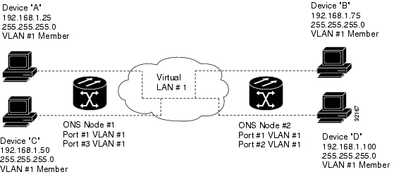
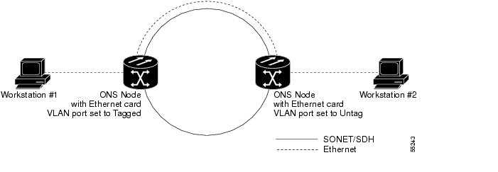
1.11.17 VLAN Cannot Connect to Network Device from Untag Port
1.12.1 OC-N Circuit Transitions to Partial State
1.12.2 AIS-V on DS3XM-6 or DS3XM-12 Unused VT Circuits
1.12.3 Circuit Creation Error with VT1.5 Circuit
1.12.4 Unable to Create Circuit From DS-3 Card to DS3XM-6 or DS3XM-12 Card
1.12.5 DS-3 Card Does Not Report AIS-P From External Equipment
1.12.6 OC-3 and DCC Limitations
1.12.7 ONS 15454 Switches Timing Reference
1.12.8 Holdover Synchronization Alarm
1.12.9 Free-Running Synchronization Mode
1.12.10 Daisy-Chained BITS Not Functioning
1.12.11 Blinking STAT LED after Installing a Card
1.13.1 Bit Errors Appear for a Traffic Card
1.13.2 Faulty Fiber-Optic Connections
1.13.3 OC-N Card Transmit and Receive Levels
1.14.1 Power Consumption for Node and Cards
General Troubleshooting
Note
The terms "Unidirectional Path Switched Ring" and "UPSR" may appear in Cisco literature. These terms do not refer to using Cisco ONS 15xxx products in a unidirectional path switched ring configuration. Rather, these terms, as well as "Path Protected Mesh Network" and "PPMN," refer generally to Cisco's path protection feature, which may be used in any topological network configuration. Cisco does not recommend using its path protection feature in any particular topological network configuration.
This chapter provides procedures for troubleshooting the most common problems encountered when operating a Cisco ONS 15454. To troubleshoot specific ONS 15454 alarms, see Chapter 2, "Alarm Troubleshooting." If you cannot find what you are looking for, contact the Cisco Technical Assistance Center (1 800 553-2447).
This chapter includes the following sections on network problems:
•
Note
•
•
•
•
•
•
The remaining sections describe symptoms, problems, and solutions that are categorized according to the following topics:
•
•
•
•
•
•
•
1.1 Troubleshooting Non-DWDM Circuit Paths with Loopbacks
Use loopbacks and hairpin circuits to test newly created SONET circuits before running live traffic or to logically locate the source of a network failure. All ONS 15454 electrical cards, OC-N cards, G-Series Ethernet cards, MXP, TXP cards, and FC_MR-4 cards allow loopbacks and hairpin test circuits. Other cards do not allow loopbacks, including E-Series Ethernet, ML-Series Ethernet, and DWDM cards such as Optical Booster (OPT-BST), Optical Preamplifier (OPT-PRE), Optical Service Channel and Combiner/Splitter Module (OSC-CSM), Band Optical Add/Drop Multiplexing (AD-xB-xx.x), and Channel Optical Add/Drop Multiplexing (AD-xC-xx.x) cards.
To create a loopback on a port, the port must be in the Out-of-Service and Management, Maintenance (OOS-MA,MT) service state. The resulting service state is Out-of-Service and Management, Loopback and Maintenance (OOS-MA,LPBK & MT).
Caution
Caution
1.1.1 Facility Loopbacks
The following sections give general information about facility loopback operations and specific information about ONS 15454 card loopback activity.
1.1.1.1 General Behavior
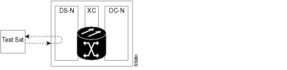
A facility (line) loopback tests the line interface unit (LIU) of a card, the electrical interface assembly (EIA), and related cabling. After applying a facility loopback on a port, use a test set to run traffic over the loopback. A successful facility loopback isolates the LIU, the EIA, or the cabling plant as the potential cause of a network problem. Figure 1-1 shows a facility loopback on a DS-N electrical card.
Figure 1-1 Facility (Line) Loopback Path on a Near-End DS-N Card
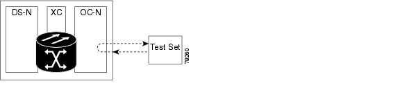
To test an OC-N card LIU, connect an optical test set to the OC-N port and perform a facility (line) loopback. Alternately, use a loopback or hairpin circuit on a card that is farther along the circuit path. Figure 1-2 shows a facility loopback on an OC-N card.
Figure 1-2 Facility (Line) Loopback Path on a Near-End OC-N Card
In CTC, OC-N cards with facility loopbacks show an icon ( Figure 1-5). Loopback icons are not shown on other cards in this release.
Figure 1-3 OC-N Facility Loopback Indicator
Caution
1.1.1.2 ONS 15454 Card Behavior
ONS 15454 port loopbacks either terminate or bridge the loopback signal. All ONS 15454 optical, electrical, Ethernet, MXP, TXP, and FC_MR-4 facility loopbacks are terminated as shown in Table 1-1.
When a port terminates a facility loopback signal, the signal only loops back to the originating port and is not transmitted downstream. When a port bridges a loopback signal, the signal loops back to the originating port and is also transmitted downstream.
Note
Table 1-1 ONS 15454 Card Facility Loopback Behavior
DS-1
Terminated
DS-3
Terminated
DS3XM-6 or DS3XM-12
Terminated
All OC-N cards
Terminated
EC-1
Terminated
G-Series Ethernet
Terminated1
MXP, MXPP trunk ports
Bridged
MXP, MXPP client ports
Terminated
TXP, MXPP trunk ports
Bridged
TXP, MXPP client ports
Terminated
1 G-Series facility loopback is terminated and no AIS is sent downstream. However, the Cisco Link Integrity signal continues to be sent downstream.
The loopback itself is listed in the Conditions window. For example, the window would list the LPBKFACILITY condition in the for a tested port. (The Alarms window will show AS-MT, which means that alarms are suppressed on the facility during loopback.)
In addition to the Conditions window listing, the following behaviors occur:
•
•
MXP, TXP, and FC_MR-4 card facility loopbacks behave differently from other ONS 15454 cards. With a client-side facility loopback, the client port service state is OOS-MA,LPBK & MT; however the remaining client and trunk ports can be in any other service state. For cards in a trunk-side facility loopback, the trunk port service state is OOS-MA,LPBK & MT service state and the remaining client and trunk ports can be in any other service state.
1.1.2 Terminal Loopbacks
The following sections give general information about terminal loopback operations and specific information about ONS 15454 card loopback activity.
1.1.2.1 General Behavior
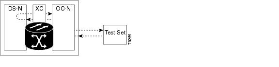
A terminal loopback tests a circuit path as it passes through the cross-connect card (XC10G) and loops back from the card with the loopback. Figure 1-4 shows a terminal loopback on an OC-N card. The test-set traffic comes into the electrical port and travels through the cross-connect card to the optical card. The terminal loopback on the optical card turns the signal around before it reaches the LIU and sends it back through the cross-connect card to the electrical card. This test verifies that the cross-connect card and terminal circuit paths are valid, but does not test the LIU on the optical card.
Figure 1-4 Terminal Loopback Path on an OC-N Card
In CTC, OC-N cards with terminal loopbacks show an icon ( Figure 1-5). Loopback icons are not shown on other cards in this release.
Figure 1-5 Terminal Loopback Indicator
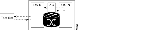
Figure 1-6 shows a terminal loopback on a DS-N electrical card. The test-set traffic comes in on the optical card and travels through the cross-connect card to the electrical card. The terminal loopback on the electrical card turns the signal around before it reaches the LIU and sends it back through the cross-connect card to the optical card. This test verifies that the cross-connect card and terminal circuit paths are valid, but does not test the LIU on the electrical card.
Figure 1-6 Terminal Loopback Path on a DS-N Card
1.1.2.2 ONS 15454 Card Behavior
ONS 15454 terminal port loopbacks can either terminate or bridge the signal. In the ONS 15454 system, all optical, electrical, Ethernet, MXP, TXP, and FC_MR-4 terminal loopbacks are terminated as shown in Table 1-2. During terminal loopbacks, some ONS 15454 cards bridge the loopback signal while others terminate it.
If a port terminates a terminal loopback signal, the signal only loops back to the originating port and is not transmitted downstream. If the port bridges a loopback signal, the signal loops back to the originating port and is also transmitted downstream.
ONS 15454 card terminal loopback bridging and terminating behaviors are listed in Table 1-2.
Note
Table 1-2 ONS 15454 Card Terminal Loopback Behavior
DS-1
Terminated
DS-3
Bridged
DS3XM-6 or DS3XM-12
Bridged
All OC-N cards
Bridged
EC-1
Bridged
G-Series Ethernet
Terminated1
MXP, MXPP trunk ports
Bridged
MXP, MXPP client ports
Terminated
TXP, MXPP trunk ports
Bridged
TXP, MXPP client ports
Terminated
1 G-Series Ethernet terminal loopback is terminated and Ethernet transmission is disabled. No AIS is inserted for Ethernet, but a TPTFAIL alarm is raised on the far-end Ethernet port.
Bridged DS-N and OC-N terminal loopback examples are shown in Figure 1-7 and Figure 1-8.
Figure 1-7 Terminal Loopback on a DS-N Card with Bridged Signal
Figure 1-8 Terminal Loopback on an OC-N Card with Bridged Signal
G-Series Ethernet cards placed in terminal loopback have different performance monitoring behavior from other ONS 15454 cards. (For more information about performance monitoring counters, see Chapter 4, "Performance Monitoring.") Setting a terminal loopback on the G-Series Ethernet card might not stop the Tx Packets counter or the Rx Packet counters on the CTC card-level view Performance > Statistics page from increasing. The counters can increment even though the loopbacked port has temporarily disabled the transmit laser and is dropping any received packets.
The Tx Packet statistic continues to increment because the statistic is not based on the packets transmitted by the transmit (Tx) laser but on the Tx signal inside the G-Series card. In normal in-service port operation, the Tx signal being recorded does result in the Tx laser transmitting packets, but in a terminal loopback this signal is being looped back within the G-Series card and does not result in the Tx laser transmitting packets.
The Rx Packet counter might also continue to increment when the G-Series card is in terminal loopback. Receive (Rx) packets from any connected device are dropped and not recorded, but the internally looped-back packets follow the G-Series card's normal receive path and register on the Rx Packet counter.
MXP and TXP card trunk and client ports have different service state behaviors and requirements from other ONS 15454 cards. The cards can simultaneously maintain different service states.
•
•
•
The loopback itself is listed in the Conditions window. For example, the window would list the LPBKTERMINAL condition or LPBKFACILITY condition for a tested port. (The Alarms window would show AS-MT, which indicates that all alarms are suppressed on the port during loopback testing.)
In addition to the Conditions window listing, the following behaviors occur:
•
•
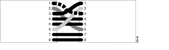
1.1.3 Hairpin Circuits
A hairpin circuit brings traffic in and out on a electrical port rather than sending the traffic onto the OC-N card. A hairpin loops back only the specific synchronous transport signal (STS) or virtual tributary (VT) circuit and does not cause an entire OC-N port to loop back, thus preventing a drop of all traffic on the OC-N port. The hairpin allows you to test a specific STS or VT circuit on nodes running live traffic. Figure 1-9 shows the hairpin circuit path on a DS-N card.
Figure 1-9 Hairpin Circuit Path on a DS-N Card
1.1.4 Cross-Connect Loopbacks
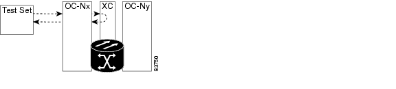
A cross-connect (XC) loopback tests an OC-N circuit path as it passes through the cross-connect card and loops back to the port being tested without affecting other traffic on the optical port. Cross-connect loopbacks are less invasive than terminal or facility loopbacks. Facility and terminal loopback testing and circuit verification often involve taking down the whole line; however, a cross-connect loopback allows you to create a loopback on any embedded channel at supported payloads of STS-1 granularity and higher. For example, you can loop back a single STS-1, STS-3c, STS-6c, etc. on an optical facility (line) without interrupting the other STS circuits.
This test can be conducted locally or remotely through the CTC interface without on-site personnel. It takes place only on an OC-N card and tests the traffic path on that STS (or higher) circuit through the port and cross-connect card. The signal path is similar to a facility loopback.
The XC loopback breaks down the existing path and creates a new cross-connect—a hairpin—while the source of the original path is set to inject a line-side AIS-P. The loopback signal path and AIS injection are shown in Figure 1-10.
Figure 1-10 Network Element with SONET Cross-Connect Loopback Function
When creating cross-connect loopbacks, consult the following rules:
•
•
1.2 Troubleshooting Electrical Circuit Paths With Loopbacks
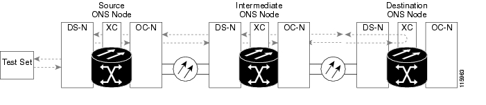
Facility (line) loopbacks, terminal (inward) loopbacks, and hairpin circuits are often used to test a circuit path through the network or to logically isolate a fault. Performing a loopback test at each point along the circuit path systematically isolates possible points of failure.
The example in this section tests an electrical circuit on a two-node bidirectional line-switched ring (BLSR). Using a series of facility loopbacks, terminal loopbacks, hairpins, and, where appropriate, cross-connect loopbacks (on optical paths carrying electrical circuits), the path of the circuit is traced and the possible points of failure are tested and eliminated. A logical progression of eight network test procedures apply to this sample scenario:
Note
West-to-east direction (left to right):
1.
2.
3.
4.
East-to-west direction (right to left):
1.
2.
3.
4.
Note
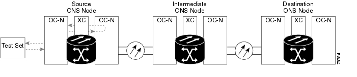
1.2.1 Perform a Facility (Line) Loopback on a Source Electrical Port (West to East)
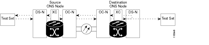
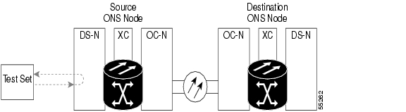
The facility (line) loopback test is performed on the node source electrical port in the network circuit; in this example, the DS-N port in the source node. Completing a successful facility (line) loopback on this port isolates the cabling, the electrical card, and the EIA as possible failure points. Figure 1-11 shows an example of a facility loopback on a source DS-N port.
Figure 1-11 Facility (Line) Loopback on a Circuit Source DS-N Port
Caution
Note
Depending upon your card type, complete the "Create the Facility (Line) Loopback on the Source DS-1, DS-3, DS3N-12, DS3i-N-12, or EC1 Port" procedure or the "Create the Facility (Line) Loopback on the Source DS3E or DS3XM Port" procedure, then test and clear the loopbacks as instructed.
Create the Facility (Line) Loopback on the Source DS-1, DS-3, DS3N-12, DS3i-N-12, or EC1 Port
Step 1
Use appropriate cabling to attach the Tx and Rx terminals of the electrical test set to the EIA connectors or DSx panel for the port you are testing. The Tx and Rx terminals connect to the same port.
Step 2
Step 3
Step 4
Step 5
Step 6
Step 7
Step 8
Note
Step 9
Test and Clear the DS-3, DS3N-12, DS3i-N-12, or EC1 Port Facility Loopback Circuit
Step 1
Step 2
Step 3
Step 4
Step 5
Step 6
Step 7
Step 8
Step 9
Create the Facility (Line) Loopback on the Source DS3E or DS3XM Port
This procedure applies to DS3E, DS3XM-6, and DS3XM-12 cards. It does not utilize the DS3XM card FEAC loopback functions. For this information, refer to the "Troubleshooting DS3XM-6 or DS3XM-12 Card Electrical Paths With FEAC Loopbacks" section.
Step 1
Use appropriate cabling to attach the Tx and Rx terminals of the electrical test set to the EIA connectors or DSx panel for the port you are testing. The Tx and Rx terminals connect to the same port.
Step 2
Step 3
Step 4
Note
Step 5
Step 6
Step 7
Step 8
Note
Step 9
Test and Clear the DS3E or DS3XM Port Facility Loopback Circuit
Step 1
Step 2
Step 3
Step 4
Note
Step 5
Step 6
Step 7
Step 8
Step 9
Test the Electrical Cabling
Step 1
If a known-good cable is not available, test the suspected bad cable with a test set. Remove the suspected bad cable from the DSx panel or the EIA and connect the cable to the Tx and Rx terminals of the test set. Run traffic to determine whether the cable is good or defective.
Step 2
Step 3
Step 4
Note
Step 5
Step 6
Step 7
Step 8
Step 9
Test the Electrical Card
Step 1
Caution
Step 2
Step 3
Step 4
Step 5
Note
Step 6
Step 7
Step 8
Step 9
Step 10
Test the EIA
Step 1
a.
b.
c.
d.
Step 2
Step 3
Note
Step 4
Step 5
Step 6
Step 7
Step 8
Step 9
Step 10
Step 11
Step 12
Step 13
Step 14
Step 15
Step 16
1.2.2 Perform a Hairpin Test on a Source-Node Electrical Port (West to East)
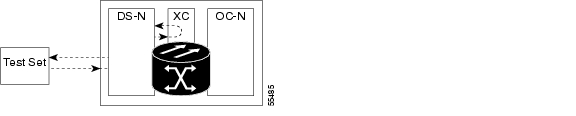
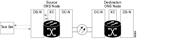
The hairpin test is performed on the cross-connect card in the network circuit. A hairpin circuit uses the same port for both source and destination. Completing a successful hairpin through the port isolates the possibility that the cross-connect card is the cause of the faulty circuit. Figure 1-12 shows an example of a hairpin loopback on a source-node port.
Figure 1-12 Hairpin on a Source-Node Port
Note
Complete the "Create the Hairpin Circuit on the Source-Node Electrical Port" procedure.
Create the Hairpin Circuit on the Source-Node Electrical Port
Step 1
a.
b.
Step 2
Step 3
a.
b.
c.
d.
e.
f.
g.
h.
i.
j.
k.
l.
Step 4
Step 5
Test and Delete the Electrical Port Hairpin Circuit
Step 1
Step 2
Step 3
a.
b.
c.
d.
e.
Step 4
Test the Standby XC10G Cross-Connect Card
Note
Step 1
a.
b.
c.
d.
Step 2
Caution
a.
b.
c.
d.
Note
Step 3
The test traffic now travels through the alternate cross-connect card.
Step 4
a.
b.
c.
d.
e.
Step 5
Retest the Original XC10G Cross-Connect Card
Step 1
a.
b.
c.
d.
Note
Step 2
Step 3
Step 4
Step 5
a.
b.
c.
d.
e.
Step 6
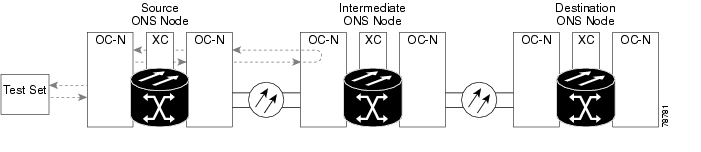
1.2.3 Perform an XC Loopback on a Destination-Node OC-N STS (West to East) Carrying an Electrical Signal
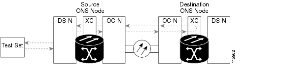
The XC loopback tests whether any problem exists on the circuit's OC-N span, isolating this span from others present on the card. The loopback occurs on the XC10G cross-connect card in a network circuit. Figure 1-13 shows an example of an XC loopback on a destination OC-N port. The traffic pattern looks similar to a terminal loopback but traffic is only carried on one STS instead of affecting the entire port.
Note
Note
Figure 1-13 XC Loopback on a Destination OC-N Port
Create the XC Loopback on a Destination-Node OCN STS
Step 1
Note
a.
b.
Step 2
Step 3
a.
b.
c.
d.
e.
f.
Step 4
a.
b.
c.
d.
e.
Step 5
Test and Clear the XC Loopback Circuit
Note
Step 1
Step 2
Step 3
a.
b.
c.
d.
Step 4
Test the Standby XC10G Cross-Connect Card
Step 1
a.
b.
c.
d.
Step 2
Caution
a.
b.
c.
d.
Note
Step 3
The test traffic now travels through the alternate cross-connect card.
Step 4
a.
b.
c.
d.
e.
Step 5
Retest the Original XC10G Cross-Connect Card
Note
Step 1
a.
b.
c.
d.
Note
Step 2
Step 3
Step 4
Step 5
a.
b.
c.
d.
Step 6
1.2.4 Perform a Terminal (Inward) Loopback on a Destination Electrical Port Port (West to East)
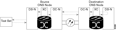
The terminal (inward) loopback test is performed on the destination-node electrical port in the circuit, such as a destination-node DS-N port or EC-1 port. You create a bidirectional circuit that starts on the source-node electrical port and loops back on the destination-node electrical port. Then you proceed with the terminal loopback test. Completing a successful terminal loopback to a destination-node electrical port verifies that the circuit is good to the destination DS-N. Figure 1-14 shows an example of a terminal loopback on a destination DS-N port.
Figure 1-14 Terminal (Inward) Loopback to a Destination DS-N Port
Caution
Note
Depending upon your card type, complete the "Create the Terminal (Inward) Loopback on a Destination DS-3, DS3N-12, DS3i-N-12, or EC1 Port" procedure or the "Create the Terminal (Inward) Loopback on a Destination DS-3E or DS3XM Port" procedure. Then test and clear the loopback as instructed.
Create the Terminal (Inward) Loopback on a Destination DS-3, DS3N-12, DS3i-N-12, or EC1 Port
Step 1
a.
b.
Step 2
Step 3
Step 4
Step 5
Step 6
Step 7
Step 8
Step 9
Step 10
Step 11
c.
d.
Step 12
Note
Note
Step 13
a.
•
•
b.
c.
d.
e.
f.
g.
Step 14
Test and Clear the DS-3, DS3N-12, DS3i-N-12, or EC1 Destination Port Terminal Loopback Circuit
Step 1
Step 2
Step 3
Step 4
Step 5
Step 6
Step 7
Step 8
Step 9
a.
b.
c.
d.
Step 10
Create the Terminal (Inward) Loopback on a Destination DS-3E or DS3XM Port
Step 1
a.
b.
c.
Step 2
Step 3
Step 4
Step 5
Step 6
Step 7
Step 8
Step 9
Step 10
d.
e.
Step 11
Note
Note
Step 12
a.
•
•
b.
c.
Note
d.
e.
f.
g.
Step 13
Test and Clear the DS-3E or DS3XM Destination Port Terminal Loopback Circuit
Step 1
Step 2
Step 3
Step 4
Note
Step 5
Step 6
Step 7
Step 8
Step 9
a.
b.
c.
d.
Step 10
Test the Destination Electrical Card
Step 1
Caution
Step 2
Step 3
Step 4
Step 5
a.
b.
Note
c.
d.
e.
f.
Step 6
a.
b.
c.
d.
Step 7
1.2.5 Perform a Facility (Line) Loopback on a Destination-Node Electrical Port (East to West)
The facility (line) loopback test is performed on the destination-node electrical port in the network circuit. Completing a successful facility (line) loopback on this port isolates the cabling, the electrical card, and the EIA as possible failure points. Figure 1-15 shows an example of a facility loopback on a destination DS-N port.
Figure 1-15 Facility (Line) Loopback on a Circuit Destination DS-N Port
Caution
Note
Depending upon your card type, complete the "Create the Facility (Line) Loopback on the Destination DS-1, DS-3, DS3N-12, DS3i-N-12, or EC1 Port" procedure or the "Create the Facility (Line) Loopback on the Source DS3E or DS3XM Port" procedure. Then test and clear the loopback as instructed.
Create the Facility (Line) Loopback on the Destination DS-1, DS-3, DS3N-12, DS3i-N-12, or EC1 Port
Step 1
a.
b.
Step 2
Step 3
Step 4
Step 5
Step 6
Step 7
Step 8
Note
Step 9
Test and Clear the DS-3, DS3N-12, DS3i-N-12, or EC1 Port Facility Loopback Circuit
Step 1
Step 2
Step 3
Step 4
Step 5
Step 6
Step 7
Step 8
Step 9
Create the Facility (Line) Loopback on the Source DS3E or DS3XM Port
This procedure applies to DS3E, DS3XM-6, and DS3XM-12 cards. It does not utilize the DS3XM card FEAC loopback functions. For this information, refer to the "Troubleshooting DS3XM-6 or DS3XM-12 Card Electrical Paths With FEAC Loopbacks" section.
Step 1
Use appropriate cabling to attach the Tx and Rx terminals of the electrical test set to the EIA connectors or DSx panel for the port you are testing. The Tx and Rx terminals connect to the same port. Adjust the test set accordingly. (Refer to manufacturer instructions for test-set use.)
Step 2
Step 3
Note
Step 4
Step 5
Step 6
Step 7
Note
Step 8
Test and Clear the DS3E or DS3XM Port Facility Loopback Circuit
Step 1
Step 2
Step 3
Step 4
Note
Step 5
Step 6
Step 7
Step 8
Step 9
Test the Electrical Cabling
Step 1
If a known-good cable is not available, test the suspected bad cable with a test set. (Refer to manufacturer instructions for test-set use.) Remove the suspected bad cable from the DSx panel or the EIA and connect the cable to the Tx and Rx terminals of the test set. Run traffic to determine whether the cable is good or defective.
Step 2
Step 3
Step 4
Note
Step 5
Step 6
Step 7
Step 8
Step 9
Test the Electrical Card
Step 1
Caution
Step 2
Step 3
Step 4
Step 5
Note
Step 6
Step 7
Step 8
Step 9
Step 10
Test the EIA
Step 1
a.
b.
c.
d.
Step 2
Step 3
Note
Step 4
Step 5
Step 6
Step 7
Step 8
Step 9
Step 10
Step 11
Step 12
Step 13
Step 14
Step 15
Step 16
1.2.6 Perform a Hairpin Test on a Destination-Node Electrical Port (East to West)
The hairpin test is performed on the cross-connect card in the network circuit. A hairpin circuit uses the same port for both source and destination. Completing a successful hairpin through the card isolates the possibility that the cross-connect card is the cause of the faulty circuit. Figure 1-16 shows an example of a hairpin loopback on a destination-node port.
Figure 1-16 Hairpin on a Destination-Node DS-N Port
Note
Complete the "Create the Hairpin Circuit on the Destination-Node Port" procedure.
Create the Hairpin Circuit on the Destination-Node Port
Step 1
a.
b.
Step 2
Step 3
a.
b.
c.
d.
e.
f.
g.
h.
i.
j.
k.
l.
Step 4
Step 5
Test and Delete the Electrical Hairpin Circuit
Step 1
Step 2
Step 3
a.
b.
c.
d.
e.
Step 4
Test the Standby XC10G Cross-Connect Card
Note
Step 1
a.
b.
c.
d.
Step 2
Caution
a.
b.
c.
d.
Note
Step 3
The test traffic now travels through the alternate cross-connect card.
Step 4
a.
b.
c.
d.
e.
Step 5
Retest the Original XC10G Cross-Connect Card
Step 1
a.
b.
c.
d.
Note
Step 2
Step 3
Step 4
Step 5
a.
b.
c.
d.
e.
Step 6
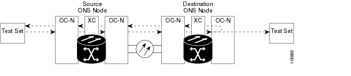
1.2.7 Perform an XC Loopback on a Source-Node OC-N STS (East to West)
Carrying an Electrical CircuitThe XC loopback tests whether any problem exists on the circuit's OC-N span, isolating this span from others present on the card. It also eliminates the cross-connect card as the source of trouble for a faulty circuit. The loopback occurs on the XC10G cross-connect card in a network circuit. Figure 1-17 shows an example of an XC loopback on a source OC-N port.
Note
Note
Figure 1-17 XC Loopback on a Source OC-N Port
Complete the "Create the XC Loopback on the Source OC-N Port Carrying an Electrical Circuit" procedure.
Create the XC Loopback on the Source OC-N Port Carrying an Electrical Circuit
Step 1
Note
a.
b.
Step 2
Step 3
a.
b.
c.
d.
e.
f.
Step 4
a.
b.
c.
d.
e.
Step 5
Test and Clear the XC Loopback Circuit
Note
Step 1
Step 2
Step 3
a.
b.
c.
d.
Step 4
Test the Standby XC10G Cross-Connect Card
Step 1
a.
b.
c.
d.
Step 2
Caution
a.
b.
c.
d.
Note
Step 3
The test traffic now travels through the alternate cross-connect card.
Step 4
a.
b.
c.
d.
e.
Step 5
Retest the Original XC10G Cross-Connect Card
Note
Step 1
a.
b.
c.
d.
Note
Step 2
Step 3
Step 4
Step 5
a.
b.
c.
d.
e.
1.2.8 Perform a Terminal (Inward) Loopback on a Source-Node Electrical Port (East to West)
The terminal (inward) loopback test is performed on the source-node electrical port in the circuit, such as a source-node DS-N port or EC-1 port. You first create a bidirectional circuit that starts on the destination-node electrical port and loops back on the source-node electrical port. Then you proceed with the terminal loopback test. Completing a successful terminal loopback to a source-node electrical port verifies that the circuit is good to the source electrical port. Figure 1-18 shows an example of a terminal loopback on a source DS-N port.
Figure 1-18 Terminal (Inward) Loopback on a Source DS-N Port
Caution
Note
Depending upon your card type, complete the "Create the Terminal (Inward) Loopback on a Source DS-1, DS-3, DS3N-12, DS3i-N-12, or EC1 Port" procedure or the "Create the Terminal (Inward) Loopback on a Source DS3E or DS3XM Port" procedure. Then test and clear the loopback as instructed.
Create the Terminal (Inward) Loopback on a Source DS-1, DS-3, DS3N-12, DS3i-N-12, or EC1 Port
Step 1
a.
b.
Step 2
Step 3
Step 4
Step 5
Step 6
Step 7
Step 8
Step 9
Step 10
Step 11
c.
d.
Step 12
Note
Note
Step 13
a.
•
•
b.
c.
d.
e.
f.
g.
Step 14
Test and Clear the DS-3, DS3N-12, DS3i-N-12, or EC1 Port Terminal Loopback
Step 1
Step 2
Step 3
Step 4
Step 5
Step 6
Step 7
Step 8
Step 9
a.
b.
c.
d.
Step 10
Create the Terminal (Inward) Loopback on a Source DS3E or DS3XM Port
Step 1
a.
b.
c.
Step 2
Step 3
Step 4
Step 5
Step 6
Step 7
Step 8
Step 9
Step 10
d.
e.
Step 11
Note
Note
Step 12
a.
•
•
b.
c.
Note
Step 13
d.
e.
f.
Step 14
Test and Clear the DS3E or DS3XM Port Terminal Loopback Circuit
Step 1
Step 2
Step 3
Step 4
Note
Step 5
Step 6
Step 7
Step 8
Step 9
a.
b.
c.
d.
Step 10
Test the Source Electrical Card
Step 1
Step 2
Step 3
Step 4
Step 5
a.
b.
Note
c.
d.
e.
f.
Step 6
a.
b.
c.
All tests for this circuit are completed.
1.3 Troubleshooting DS3XM-6 or DS3XM-12 Card Electrical Paths With FEAC Loopbacks
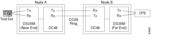
The DS3XM-6 card and DS3XM-12 cards support FEAC functions that are not available on basic DS-3 cards. Click the DS3XM-6 or DS3XM-12 Maintenance > DS1 tab at the card view to reveal the two additional function columns. Figure 1-19 shows the DS3 subtab and the additional Send Code and Inhibit FE Lbk function columns.
Figure 1-19 Accessing FEAC Functions on the DS3XM-6 Card
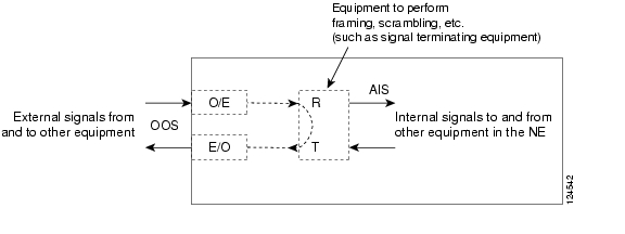
The "far end" in FEAC refers to the equipment connected to the DS3XM card and not to the far end of a circuit. In Figure 1-20, if a DS3XM-6 (near-end) port is configured to send a line loop code, the code will be sent to the connected test set, not the DS3XM-6 (far-end) port.
Figure 1-20 Diagram of FEAC Circuit
1.3.1 FEAC Send Code
The Send Code column on the DS3XM-6 or DS3XM-12 card Maintenance tab only applies to OOS-MA,MT ports configured for CBIT framing. The column lets a user select No Code (the default) or line loop code. Selecting Line Loop Code inserts a line loop activate FEAC in the CBIT overhead transmitting to the connected facility (line). This code initiates a loopback from the facility to the ONS 15454. Selecting No Code sends a line-loop-deactivate FEAC code to the connected equipment, which will remove the loopback. You can also insert a FEAC for the 28 individual DS-1 circuits transmuxed into a DS-3 circuit.
1.3.2 DS-3E and DS3i-N-12 Inhibit Loopback
DS-3E and DS-3i-N-12 cards respond to (but do not send) DS-3-level FEAC codes. You can inhibit FEAC response on ports for these cards using the Inhibit Lbk check box on their Maintenance windows.
1.3.3 DS3XM-6 and DS3XM-12 Inhibit FEAC Loopback
DS3XM-6 and DS3XM-12 ports and transmuxed DS-1 circuits initiate loopbacks when they receive FEAC line loop codes. If the Inhibit FE Lbk check box is checked for a DS-3 port, that port ignores any FEAC line loop codes it receives and will not loop back (return them). Only DS-3 ports can be configured to inhibit FEAC loopback responses; individual DS-1 ports (accessed on the DS3XM DS1 tab) cannot inhibit their responses. If you inhibit a DS-3 port's far end loopback response, this DS-3 port and the DS-1 lines it contains are not restricted from terminal (inward) or facility (line) loopbacks.
1.3.4 FEAC Alarms
When an ONS 15454 port receives an activation code for a FEAC loopback, it raises the "LPBKDS1FEAC" condition on page 2-166 or the "LPBKDS3FEAC" condition on page 2-166. The condition clears when the port receives the command to deactivate the FEAC loopback. If a node sends a FEAC loopback command to the far end, the sending node raises a "LPBKDS1FEAC-CMD" condition on page 2-166 or the "LPBKDS3FEAC-CMD" condition on page 2-167 for the near-end port.
1.4 Troubleshooting Optical Circuit Paths With Loopbacks
Facility (line) loopbacks, terminal (inward) loopbacks, and cross-connect loopback circuits are often used together to test the circuit path through the network or to logically isolate a fault. Performing a loopback test at each point along the circuit path systematically isolates possible points of failure.
The procedures in this section apply to OC-N cards. (For instructions on G-Series Ethernet cards, go to the "Troubleshooting Ethernet Circuit Paths With Loopbacks" section. For information about troubleshooting MXP and TXP cards, go to the "Troubleshooting MXP, TXP, or FC_MR-4 Circuit Paths With Loopbacks" section.) The example in this section tests an OC-N circuit on a three-node BLSR. Using a series of facility, cross-connect, and terminal (inward) loopbacks, the example scenario traces the circuit path, tests the possible failure points, and eliminates them. The logical progression contains seven network test procedures:
Note
1.
2.
3.
4.
5.
6.
7.
Note
1.4.1 Perform a Facility (Line) Loopback on a Source-Node Optical Port
The facility (line) loopback test is performed on the node source port in the network circuit. In the testing situation used in this example, the source OC-N port in the source node. Completing a successful facility (line) loopback on this port isolates the OC-N port as a possible failure point. Figure 1-21 shows an example of a facility loopback on a circuit source OC-N port.
Figure 1-21 Facility (Line) Loopback on a Circuit Source OC-N Port
Caution
Complete the "Create the Facility (Line) Loopback on the Source Optical Port" procedure.
Create the Facility (Line) Loopback on the Source Optical Port
Step 1
Note
Use appropriate cabling to attach the Tx and Rx terminals of the optical test set to the port you are testing. The Tx and Rx terminals connect to the same port. Adjust the test set accordingly. (Refer to manufacturer instructions for test-set use.)
Step 2
Step 3
Step 4
Step 5
Step 6
Step 7
Note
Step 8
Test and Clear the Facility (Line) Loopback Circuit
Step 1
Step 2
Step 3
a.
b.
c.
d.
e.
Step 4
Test the OC-N Card
Step 1
Caution
Step 2
Step 3
Step 4
Step 5
a.
b.
c.
d.
e.
Step 6
1.4.2 Perform a Terminal (Inward) Loopback on a Source-Node Optical Port
The terminal (inward) loopback test is performed on the source-node optical port. For the circuit in this example, it is the source OC-N port in the source node. You first create a bidirectional circuit that starts on the node destination optical port and loops back on the node source optical port. You then proceed with the terminal loopback test. Completing a successful terminal loopback to a node source port verifies that the circuit is good to the source port. Figure 1-22 shows an example of a terminal loopback on a source OC-N port.
Figure 1-22 Terminal (Inward) Loopback on a Source-Node OC-N Port
OC-N cards placed in terminal loopback state display an icon in the CTC graphical user interface (GUI), shown in Figure 1-23.
Figure 1-23 Terminal Loopback Indicator
Caution
Complete the "Create the Terminal (Inward) Loopback on a Source-Node Optical Port" procedure.
Create the Terminal (Inward) Loopback on a Source-Node Optical Port
Step 1
Note
a.
b.
c.
Step 2
a.
b.
c.
d.
e.
f.
g.
h.
i.
j.
k.
Step 3
Note
Step 4
a.
b.
c.
d.
e.
f.
Step 5
Test and Clear the Terminal Loopback Circuit
Step 1
Step 2
Step 3
a.
b.
c.
d.
e.
f.
Step 4
a.
b.
c.
d.
Step 5
Test the Optical Card
Step 1
Step 2
Step 3
Step 4
Step 5
a.
b.
c.
d.
e.
f.
Step 6
a.
b.
c.
d.
Step 7
1.4.3 Perform an XC Loopback on the Source Optical Port
Note
Note
The XC loopback test occurs on the XC10G cross-connect card in a network circuit. Completing a successful XC loopback from an OC-N card through the cross-connect card eliminates the cross-connect card as the source of trouble for a faulty circuit. Figure 1-24 shows an example of an XC loopback path on a source OC-N port.
Figure 1-24 XC Loopback on a Source OC-N Port
Complete the "Create the XC Loopback on the Source-Node Optical Port" procedure.
Create the XC Loopback on the Source-Node Optical Port
Step 1
Note
a.
b.
Step 2
Step 3
a.
b.
c.
d.
e.
f.
Step 4
a.
b.
c.
d.
e.
Step 5
Test and Clear the XC Loopback Circuit
Note
Step 1
Step 2
Step 3
a.
b.
c.
d.
Step 4
Test the Standby XC10G Cross-Connect Card
Note
Step 1
a.
b.
c.
d.
Step 2
Caution
a.
b.
c.
d.
Note
Step 3
The test traffic now travels through the alternate cross-connect card.
Step 4
a.
b.
c.
d.
e.
Step 5
Retest the Original XC10G Cross-Connect Card
Note
Step 1
a.
b.
c.
d.
Note
Step 2
Step 3
Step 4
Step 5
a.
b.
c.
d.
Step 6
1.4.4 Perform a Facility (Line) Loopback on an Intermediate-Node Optical Port
Performing the facility (line) loopback test on an intermediate port isolates whether this node is causing circuit failure. In the situation shown in Figure 1-25, the test is being performed on an intermediate OC-N port.
Figure 1-25 Facility (Line) Loopback Path to an Intermediate-Node OC-N Port
Caution
Complete the "Create a Facility (Line) Loopback on an Intermediate-Node Optical Port" procedure.
Create a Facility (Line) Loopback on an Intermediate-Node Optical Port
Step 1
Note
a.
b.
Step 2
Step 3
a.
b.
c.
d.
e.
f.
g.
h.
i.
j.
k.
Step 4
Note
Step 5
a.
•
•
b.
c.
d.
e.
f.
g.
Step 6
Test and Clear the Facility (Line) Loopback Circuit
Step 1
Step 2
Step 3
a.
b.
c.
d.
e.
Step 4
a.
b.
c.
d.
Step 5
Test the Optical Card
Step 1
Caution
Step 2
Step 3
Step 4
Step 5
a.
b.
c.
d.
e.
Step 6
a.
b.
c.
d.
Step 7
1.4.5 Perform a Terminal (Inward) Loopback on Intermediate-Node Optical Ports
In the next troubleshooting test, you perform a terminal loopback on the intermediate-node port to isolate whether the destination port is causing circuit trouble. In the example situation in Figure 1-26, the terminal loopback is performed on an intermediate optical port in the circuit. You first create a bidirectional circuit that originates on the source-node optical port and loops back on the intermediate-node port. You then proceed with the terminal loopback test. If you successfully complete a terminal loopback on the node, this node is excluded from possible sources of circuit trouble.
Figure 1-26 Terminal Loopback Path to an Intermediate-Node OC-N Port
OC-N cards placed in facility loopback state display an icon, shown in Figure 1-27.
Figure 1-27 Facility Loopback Indicator
Caution
Complete the "Create a Terminal Loopback on Intermediate-Node Optical Ports" procedure.
Create a Terminal Loopback on Intermediate-Node Optical Ports
Step 1
Note
a.
b.
Step 2
Step 3
a.
b.
c.
d.
e.
f.
g.
h.
i.
j.
k.
Step 4
Note
Step 5
a.
•
•
b.
c.
d.
e.
f.
g.
Step 6
Test and Clear the Optical Terminal Loopback Circuit
Step 1
Step 2
Step 3
a.
b.
c.
d.
e.
f.
Step 4
a.
b.
c.
d.
Step 5
Test the Optical Card
Step 1
Caution
Step 2
Step 3
Step 4
Step 5
a.
b.
c.
d.
e.
f.
Step 6
a.
b.
c.
d.
Step 7
1.4.6 Perform a Facility (Line) Loopback on a Destination-Node Optical Port
You perform a facility (line) loopback test at the destination port to determine whether this local port is the source of circuit trouble. The example in Figure 1-28 shows a facility loopback being performed on a destination-node OC-N port.
Figure 1-28 Facility (Line) Loopback Path to a Destination-Node OC-N Port
Caution
Complete the "Create the Facility (Line) Loopback on a Destination-Node Optical Port" procedure.
Create the Facility (Line) Loopback on a Destination-Node Optical Port
Step 1
Note
a.
b.
Step 2
Step 3
a.
b.
c.
d.
e.
f.
g.
h.
i.
j.
k.
Step 4
Note
Step 5
a.
•
•
b.
c.
d.
e.
f.
g.
Step 6
Test and Clear the Optical Facility (Line) Loopback Circuit
Step 1
Step 2
Step 3
a.
b.
c.
d.
e.
Step 4
a.
b.
c.
d.
Step 5
Test the Optical Card
Step 1
Caution
Step 2
Step 3
Step 4
Step 5
a.
b.
c.
d.
e.
Step 6
a.
b.
c.
d.
Step 7
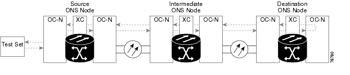
1.4.7 Perform a Terminal Loopback on a Destination-Node Optical Port
The terminal loopback at the destination-node port is the final local hardware error elimination in the circuit troubleshooting process. If this test is completed successfully, you have verified that the circuit is good up to the destination port. The example in Figure 1-29 shows a terminal loopback on an intermediate-node destination OC-N port.
Figure 1-29 Terminal Loopback Path to a Destination-Node OC-N Port
Caution
Complete the "Create the Terminal Loopback on a Destination-Node Optical Port" procedure.
Create the Terminal Loopback on a Destination-Node Optical Port
Step 1
Note
a.
b.
Step 2
Step 3
a.
b.
c.
d.
e.
f.
g.
h.
i.
j.
k.
Step 4
Note
Step 5
a.
•
•
b.
c.
d.
e.
f.
g.
Step 6
Test and Clear the Optical Terminal Loopback Circuit
Step 1
Step 2
Step 3
a.
b.
c.
d.
e.
f.
Step 4
a.
b.
c.
d.
The entire circuit path has now passed its comprehensive series of loopback tests. This circuit qualifies to carry live traffic.
Step 5
Step 6
Test the Optical Card
Step 1
Caution
Step 2
Step 3
Step 4
Step 5
a.
b.
c.
d.
e.
f.
Step 6
a.
b.
c.
d.
The entire circuit path has now passed its comprehensive series of loopback tests. This circuit qualifies to carry live traffic.
1.5 Troubleshooting Ethernet Circuit Paths With Loopbacks
Facility (line) loopbacks, terminal (inward) loopbacks, and cross-connect loopback circuits are often used together to test the circuit path through the network or to logically isolate a fault. Performing a loopback test at each point along the circuit path systematically isolates possible points of failure.
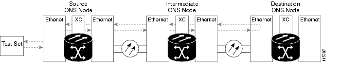
You can use these procedures on G-Series Ethernet cards (G1000-2) and CE_100T-8 cards but not on E-Series or ML-Series Ethernet cards. The example in this section tests a G1000 circuit on a three-node BLSR. Using a series of facility (line) loopbacks and terminal (inward) loopbacks, the example scenario traces the circuit path, tests the possible failure points, and eliminates them. The logical progression contains six network test procedures:
Note
1.
2.
3.
4.
5.
6.
Note
1.5.1 Perform a Facility (Line) Loopback on a Source-Node Ethernet Port
The facility (line) loopback test is performed on the node source port in the network circuit. In the testing situation used in this example, the source G1000 port in the source node. Completing a successful facility (line) loopback on this port isolates the G1000 port as a possible failure point. Figure 1-21 shows an example of a facility loopback on a circuit source Ethernet port.
Note
Figure 1-30 Facility (Line) Loopback on a Circuit Source Ethernet Port
Caution
Complete the "Create the Facility (Line) Loopback on the Source-Node Ethernet Port" procedure.
Create the Facility (Line) Loopback on the Source-Node Ethernet Port
Step 1
Note
Use appropriate cabling to attach the Tx and Rx terminals of the optical test set to the port you are testing. The Tx and Rx terminals connect to the same port.
Step 2
Step 3
Step 4
Step 5
Step 6
Step 7
Step 8
Note
Step 9
Test and Clear the Facility (Line) Loopback Circuit
Step 1
Step 2
Step 3
a.
b.
c.
d.
e.
Step 4
Test the Ethernet Card
Step 1
Caution
Step 2
Step 3
Step 4
Step 5
a.
b.
c.
d.
e.
Step 6
1.5.2 Perform a Terminal (Inward) Loopback on a Source-Node Ethernet Port
The terminal (inward) loopback test is performed on the node source Ethernet port. For the circuit in this example, it is the source G1000 port in the source node. You first create a bidirectional circuit that starts on the node destination G1000 port and loops back on the node source G1000 port.You then proceed with the terminal loopback test. Completing a successful terminal loopback to a node source port verifies that the circuit is good to the source port. Figure 1-31 shows terminal loopback on a G-Series port.
Note
Figure 1-31 Terminal (Inward) Loopback on a G-Series Port
Caution
Complete the "Create the Terminal (Inward) Loopback on a Source-Node Ethernet Port" procedure.
Create the Terminal (Inward) Loopback on a Source-Node Ethernet Port
Step 1
Note
a.
b.
Step 2
Step 3
a.
b.
c.
d.
e.
f.
g.
h.
i.
j.
k.
Step 4
Note
Step 5
a.
b.
c.
d.
e.
f.
Step 6
Test and Clear the Ethernet Terminal Loopback Circuit
Step 1
Step 2
Step 3
a.
b.
c.
d.
e.
f.
Step 4
a.
b.
c.
d.
Step 5
Test the Ethernet Card
Step 1
Caution
Step 2
Step 3
Step 4
Step 5
a.
b.
c.
d.
e.
f.
Step 6
a.
b.
c.
d.
Step 7
1.5.3 Create a Facility (Line) Loopback on an Intermediate-Node Ethernet Port
Performing the facility (line) loopback test on an intermediate port isolates whether this node is causing circuit failure. It is shown in Figure 1-32.
Figure 1-32 Facility (Line) Loopback on an Intermediate-Node Ethernet Port
Caution
Complete the "Create a Facility (Line) Loopback on an Intermediate-Node Ethernet Port" procedure.
Create a Facility (Line) Loopback on an Intermediate-Node Ethernet Port
Step 1
Note
a.
b.
Step 2
Step 3
a.
b.
c.
d.
e.
f.
g.
h.
i.
j.
k.
Step 4
Note
Step 5
a.
•
•
b.
c.
d.
e.
f.
g.
Step 6
Test and Clear the Ethernet Facility (Line) Loopback Circuit
Step 1
Step 2
Step 3
a.
b.
c.
d.
e.
Step 4
a.
b.
c.
d.
Step 5
Test the Ethernet Card
Step 1
Caution
Step 2
Step 3
Step 4
Step 5
a.
b.
c.
d.
e.
Step 6
a.
b.
c.
d.
Step 7
1.5.4 Create a Terminal (Inward) Loopback on Intermediate-Node Ethernet Ports
In the next troubleshooting test, you perform a terminal loopback on the intermediate-node port to isolate whether the destination port is causing circuit trouble. In the example situation in Figure 1-33, the terminal loopback is performed on an intermediate Ethernet port in the circuit. You first create a bidirectional circuit that originates on the source-node Ethernet port and loops back on the intermediate-node port. You then proceed with the terminal loopback test. If you successfully complete a terminal loopback on the node, this node is excluded from possible sources of circuit trouble.
Figure 1-33 Terminal Loopback on an Intermediate-Node Ethernet Port
Caution
Complete the "Create a Terminal Loopback on Intermediate-Node Ethernet Ports" procedure.
Create a Terminal Loopback on Intermediate-Node Ethernet Ports
Step 1
Note
a.
b.
Step 2
Step 3
a.
b.
c.
d.
e.
f.
g.
h.
i.
j.
k.
Step 4
Note
Step 5
a.
•
•
b.
c.
d.
e.
f.
g.
Step 6
Test and Clear the Ethernet Terminal Loopback Circuit
Step 1
Step 2
Step 3
a.
b.
c.
d.
e.
f.
Step 4
a.
b.
c.
d.
Step 5
Test the Ethernet Card
Step 1
Caution
Step 2
Step 3
Step 4
Step 5
a.
b.
c.
d.
e.
f.
Step 6
a.
b.
c.
d.
Step 7
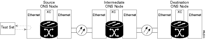
1.5.5 Perform a Facility (Line) Loopback on a Destination-Node Ethernet Port
You perform a facility (line) loopback test at the destination port to determine whether this local port is the source of circuit trouble. The example in Figure 1-34 shows a facility loopback being performed on an Ethernet port.
Figure 1-34 Facility (Line) Loopback on a Destination-Node Ethernet Port
Caution
Complete the "Create the Facility (Line) Loopback on a Destination-Node Ethernet Port" procedure.
Create the Facility (Line) Loopback on a Destination-Node Ethernet Port
Step 1
Note
a.
b.
Step 2
Step 3
a.
b.
c.
d.
e.
f.
g.
h.
i.
j.
k.
Step 4
Note
Step 5
a.
•
•
b.
c.
d.
e.
f.
g.
Step 6
Test and Clear the Ethernet Facility (Line) Loopback Circuit
Step 1
Step 2
Step 3
a.
b.
c.
d.
e.
Step 4
a.
b.
c.
d.
Step 5
Test the Ethernet Card
Step 1
Caution
Step 2
Step 3
Step 4
Step 5
a.
b.
c.
d.
e.
Step 6
a.
b.
c.
d.
Step 7
1.5.6 Perform a Terminal Loopback on a Destination-Node Ethernet Port
The terminal loopback at the destination-node port is the final local hardware error elimination in the circuit troubleshooting process. If this test is completed successfully, you have verified that the circuit is good up to the destination port. The example in Figure 1-29 shows a terminal loopback on an intermediate-node destination Ethernet port.
Figure 1-35 Terminal Loopback on a Destination-Node Ethernet Port
Caution
Complete the "Create the Terminal Loopback on a Destination-Node Ethernet Port" procedure.
Create the Terminal Loopback on a Destination-Node Ethernet Port
Step 1
Note
a.
b.
Step 2
Step 3
a.
b.
c.
d.
e.
f.
g.
h.
i.
j.
k.
Step 4
Note
Step 5
a.
•
•
b.
c.
d.
e.
f.
g.
Step 6
Test and Clear the Ethernet Terminal Loopback Circuit
Step 1
Step 2
Step 3
a.
b.
c.
d.
e.
f.
Step 4
a.
b.
c.
d.
The entire circuit path has now passed its comprehensive series of loopback tests. This circuit qualifies to carry live traffic.
Step 5
Step 6
Test the Ethernet Card
Step 1
Caution
Step 2
Step 3
Step 4
Step 5
a.
b.
c.
d.
e.
f.
Step 6
a.
b.
c.
d.
The entire circuit path has now passed its comprehensive series of loopback tests. This circuit qualifies to carry live traffic.
1.6 Troubleshooting MXP, TXP, or FC_MR-4 Circuit Paths With Loopbacks
Facility (line) loopbacks, terminal (inward) loopbacks, and cross-connect loopback circuits are often used together to test the circuit path through the network or to logically isolate a fault. Performing a loopback test at each point along the circuit path systematically isolates possible points of failure. MXP/TXP/FC_MR-4 loopback tests differ from electrical, optical, and Ethernet testing in that loopback testing does not require circuit creation. MXP, TXP, and FC_MR-4 client ports are statically mapped to the trunk ports so no signal needs to traverse the cross-connect card (in a circuit) to test the loopback.
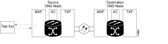
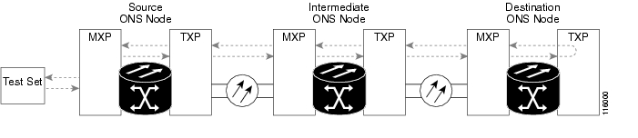
You can use these procedures on transponder cards (TXP, TXPP), muxponder cards (MXP, MXPP), and fibre channel data storage (FC_MR-4) cards. The example in this section tests an MXP/TXP/FC_MR-4 circuit on a three-node BLSR. Using a series of facility (line) loopbacks and terminal (inward) loopbacks, the example scenario traces the circuit path, tests the possible failure points, and eliminates them. The logical progression contains seven network test procedures:
Note
Note
1.
2.
3.
4.
5.
6.
Note
1.6.1 Perform a Facility (Line) Loopback on a Source-Node MXP/TXP/FC_MR-4 Port
The facility (line) loopback test is performed on the node source port in the network circuit. In the testing situation used in this example, the source muxponder or transponder port in the source node. Completing a successful facility (line) loopback on this port isolates the MXP/TXP/FC_MR-4 port as a possible failure point. Figure 1-36 shows an example of a facility loopback on a circuit source MXP/TXP/FC_MR-4 port.
Figure 1-36 Facility (Line) Loopback on a Circuit Source MXP/TXP/FC_MR-4 Port
Caution
Complete the "Create the Facility (Line) Loopback on the Source-Node MXP/TXP/FC_MR-4 Port" procedure.
Create the Facility (Line) Loopback on the Source-Node MXP/TXP/FC_MR-4 Port
Step 1
Note
Use appropriate cabling to attach the Tx and Rx terminals of the optical test set to the port you are testing. The Tx and Rx terminals connect to the same port.
Step 2
Step 3
Step 4
Step 5
Step 6
Step 7
Step 8
Note
Step 9
Test and Clear the MXP/TXP/FC_MR-4 Facility (Line) Loopback Circuit
Step 1
Step 2
Step 3
a.
b.
c.
d.
e.
Step 4
Test the MXP/TXP/FC_MR-4 Card
Step 1
Caution
Step 2
Step 3
Step 4
Step 5
a.
b.
c.
d.
e.
Step 6
1.6.2 Perform a Terminal (Inward) Loopback on a Source-Node MXP/TXP/FC_MR-4 Port
The terminal (inward) loopback test is performed on the node source MXP/TXP/FC_MR-4 muxponder or transponder port. For the circuit in this example, it is the source MXP port in the source node. Completing a successful terminal loopback to a node source port verifies that the circuit is good to the source port. Figure 1-37 shows an example of a terminal loopback on a source MXP/TXP/FC_MR-4 port.
Figure 1-37 Terminal (Inward) Loopback on a Source-Node MXP/TXP/FC_MR-4 Port
Caution
Complete the "Create the Terminal (Inward) Loopback on a Source-Node MXP/TXP/FC_MR-4 Port" procedure.
Create the Terminal (Inward) Loopback on a Source-Node MXP/TXP/FC_MR-4 Port
Step 1
Note
a.
b.
Step 2
Step 3
Step 4
Step 5
Step 6
Step 7
Step 8
Step 9
Test and Clear the MXP/TXP/FC_MR-4 Port Terminal Loopback Circuit
Step 1
Step 2
Step 3
a.
b.
c.
d.
e.
f.
Step 4
Test the MXP/TXP/FC_MR-4 Card
Step 1
Caution
Step 2
Step 3
Step 4
Step 5
a.
b.
c.
d.
e.
f.
Step 6
1.6.3 Create a Facility (Line) Loopback on an Intermediate-Node MXP/TXP/FC_MR-4 Port
Performing the facility (line) loopback test on an intermediate port isolates whether this node is causing circuit failure. In the situation shown in Figure 1-38, the test is being performed on an intermediate MXP/TXP/FC_MR-4 port.
Figure 1-38 Facility (Line) Loopback on an Intermediate-Node MXP/TXP/FC_MR-4 Port
Caution
Complete the "Create a Facility (Line) Loopback on an Intermediate-Node MXP/TXP/FC_MR-4 Port" procedure.
Create a Facility (Line) Loopback on an Intermediate-Node MXP/TXP/FC_MR-4 Port
Step 1
Note
a.
b.
Step 2
Step 3
Step 4
Step 5
Step 6
Step 7
Step 8
Step 9
Test and Clear the MXP/TXP/FC_MR-4 Port Facility (Line) Loopback Circuit
Step 1
Step 2
Step 3
a.
b.
c.
d.
e.
Step 4
Test the MXP/TXP/FC_MR-4 Card
Step 1
Caution
Step 2
Step 3
Step 4
Step 5
a.
b.
c.
d.
e.
Step 6
1.6.4 Create a Terminal (Inward) Loopback on Intermediate-Node MXP/TXP/FC_MR-4 Ports
In the next troubleshooting test, you perform a terminal loopback on the intermediate-node port to isolate whether the destination port is causing circuit trouble. In the example situation in Figure 1-39, the terminal loopback is performed on an intermediate MXP/TXP/FC_MR-4 port in the circuit. If you successfully complete a terminal loopback on the node, this node is excluded from possible sources of circuit trouble.
Figure 1-39 Terminal Loopback on an Intermediate-Node MXP/TXP/FC_MR-4 Port
Caution
Complete the "Create a Terminal Loopback on Intermediate-Node MXP/TXP/FC_MR-4 Ports" procedure.
Create a Terminal Loopback on Intermediate-Node MXP/TXP/FC_MR-4 Ports
Step 1
Note
a.
b.
Step 2
Step 3
a.
•
•
b.
c.
d.
e.
f.
g.
Step 4
Test and Clear the MXP/TXP/FC_MR-4 Terminal Loopback Circuit
Step 1
Step 2
Step 3
a.
b.
c.
d.
e.
f.
Step 4
Test the MXP/TXP/FC_MR-4 Card
Step 1
Caution
Step 2
Step 3
Step 4
Step 5
a.
b.
c.
d.
e.
f.
Step 6
1.6.5 Perform a Facility (Line) Loopback on a Destination-Node MXP/TXP/FC_MR-4 Port
You perform a facility (line) loopback test at the destination port to determine whether this local port is the source of circuit trouble. The example in Figure 1-40 shows a facility loopback being performed on an MXP/TXP/FC_MR-4 port.
Figure 1-40 Facility (Line) Loopback on a Destination-Node MXP/TXP/FC_MR-4 Port
Caution
Complete the "Create the Facility (Line) Loopback on a Destination-Node MXP/TXP/FC_MR-4 Port" procedure.
Create the Facility (Line) Loopback on a Destination-Node MXP/TXP/FC_MR-4 Port
Step 1
Note
a.
b.
Step 2
Step 3
a.
•
•
b.
c.
d.
e.
f.
g.
Step 4
Test and Clear the MXP/TXP/FC_MR-4 Facility (Line) Loopback Circuit
Step 1
Step 2
Step 3
a.
b.
c.
d.
e.
Step 4
Test the MXP/TXP/FC_MR-4 Card
Step 1
Caution
Step 2
Step 3
Step 4
Step 5
a.
b.
c.
d.
e.
Step 6
1.6.6 Perform a Terminal Loopback on a Destination-Node MXP/TXP/FC_MR-4 Port
The terminal loopback at the destination-node port is the final local hardware error elimination in the circuit troubleshooting process. If this test is completed successfully, you have verified that the circuit is good up to the destination port. The example in Figure 1-29 shows a terminal loopback on an intermediate-node destination MXP/TXP/FC_MR-4 port.
Figure 1-41 Terminal Loopback on a Destination-Node MXP/TXP/FC_MR-4 Port
Caution
Complete the "Create the Terminal Loopback on a Destination-Node MXP/TXP/FC_MR-4 Port" procedure.
Create the Terminal Loopback on a Destination-Node MXP/TXP/FC_MR-4 Port
Step 1
Note
a.
b.
Step 2
Step 3
Note
Step 4
a.
•
•
b.
c.
d.
e.
f.
g.
Step 5
Test and Clear the MXP/TXP/FC_MR-4 Terminal Loopback Circuit
Step 1
Step 2
Step 3
a.
b.
c.
d.
e.
f.
Step 4
Step 5
Test the MXP/TXP/FC_MR-4 Card
Step 1
Caution
Step 2
Step 3
Step 4
Step 5
a.
b.
c.
d.
e.
f.
The entire circuit path has now passed its comprehensive series of loopback tests. This circuit qualifies to carry live traffic.
1.7 Troubleshooting DWDM Circuit Paths With ITU-T G.709 Monitoring
This section provides an overview of the optical transport network (OTN) specified in ITU-T G.709 Network Node Interface for the Optical Transport Network, and provides troubleshooting procedures for DWDM circuit paths in the ITU-T G.709 OTN using performance monitoring and threshold crossing alerts (TCAs).
1.7.1 G.709 Monitoring in Optical Transport Networks
Recommendation ITU-T G.709 is part of a suite of recommendations covering the full functionality of an OTN. ITU-T G.709 takes single-wavelength SONET technology a step further by enabling transparent optical wavelength-based networks. It adds extra overhead to existing SONET, Ethernet, or asynchronous transfer mode (ATM) bit streams for performance management and improvement.
ITU-T G.709 adds the operations, administration, maintenance and provisioning (OAM&P) functionality of SONET/SDH to DWDM optical networks.
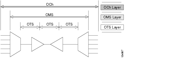
Like traditional SONET networks, ITU-T G.709 optical networks have a layered design ( Figure 1-42). This structure enables localized monitoring that helps you isolate and troubleshoot network problems.
Figure 1-42 Optical Transport Network Layers
1.7.2 Optical Channel Layer
The optical channel (OCh) layer is the outermost part of the OTN and spans from client to client. The optical channel is built as follows:
1.
2.
3.
4.
1.7.3 Optical Multiplex Section Layer
The optical multiplex section (OMS) of the OTN allows carriers to identify errors occurring within DWDM network sections. The OMS layer consists of a payload and an overhead (OMS-OH). It supports the ability to monitor multiplexed sections of the network, for example the span between an optical multiplexer such as the 3 2MUX-O and a demultiplexer such as the 32 DMX-O.
1.7.4 Optical Transmission Section Layer
The optical transmission section (OTS) layer supports monitoring partial spans of a network's multiplexed sections. This layer consists of a payload and an overhead (OTS-OH). It is a transmission span between two elements in an optical network, such as between:
•
•
•
1.7.5 Performance Monitoring Counters and Threshold Crossing Alerts
Performance monitoring (PM) counters and TCAs can be used for identifying trouble and troubleshooting problems in ITU-T G.709 optical transport networks. ITU-T Recommendation M.2401 recommends that the following PM parameters be monitored at the ODUk Layer:
•
•
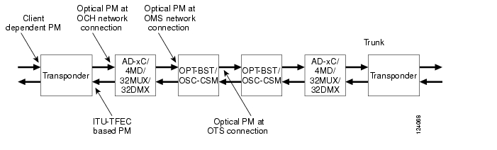
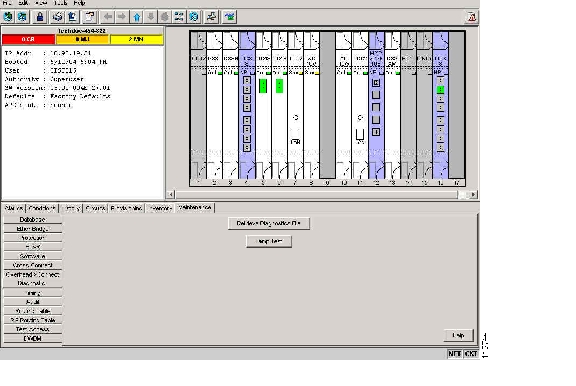
Different performance monitoring count parameters are associated with different read points in a network. Figure 1-43 illustrates the performance monitoring read points that are useful in identifying DWDM circuit points of failure. Chapter 4, "Performance Monitoring," lists all PM parameters and provides block diagrams of signal entry points, exit points and interconnections between the individual circuit cards. Consult these specifications to determine which performance monitoring parameters are associated with the system points you want to monitor or provision with CTC or TL1. The monitoring points can vary according to your configuration.
Figure 1-43 Performance Monitoring Points on ONS DWDM
TCAs are used to monitor performance through the management interface by indicating whether preset thresholds have been crossed, or whether a transmission (such as a laser transmission) is degraded. TCAs are not associated with severity levels. They are usually associated with rate, counter, and percentage parameters that are available at transponder monitoring points. Chapter 4, "Performance Monitoring," contains more information about these alerts.
Select and complete the provisioning procedure below according to your network parameters.
Complete the following procedure to provision default node ODUk BBE and SES PM thresholds for TXP cards.
Set Node Default BBE or SES Card Thresholds
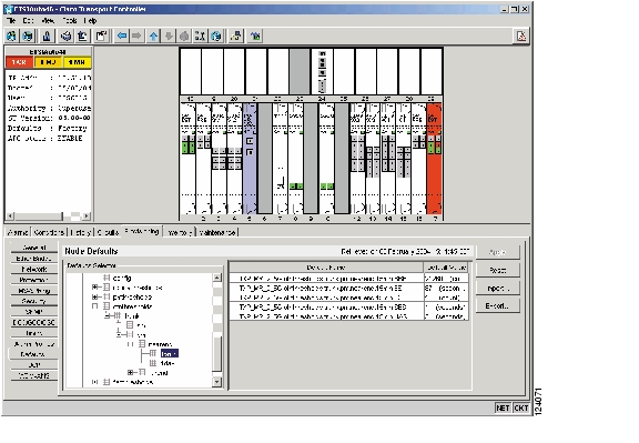
Step 1
Figure 1-44 Set Default BBE/SES Card Thresholds
Step 2
Complete the following procedure to provision BBE or SES PM thresholds in CTC for an individual TXP card.
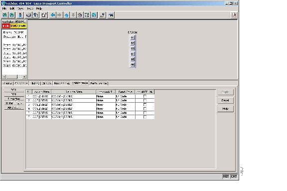
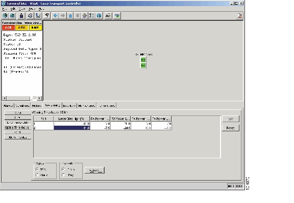
Provision Individual Card BBE or SES Thresholds in CTC
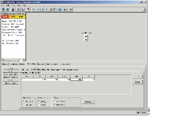
Step 1
(In this example, other transponder and muxponder cards are also applicable, such as TXP_MR_10G, TXPP_MR_2.5G, and MXP_2.5G_10G.)Step 2
Figure 1-45 Provision Card BBE/SES Thresholds
Step 3
Step 4
Step 5
Step 6
Complete the following procedure if you wish to provision PM thresholds in TL1 rather than in CTC.
Provision Card PM Thresholds Using TL1
Step 1
Step 2
set-th-{och,clnt}::aid:ctag::montype,thlev,,,[tmper];Where:
•
•
–
–
–
•
•
Note
Complete the following procedure to provision TCA thresholds in CTC.
Provision Optical TCA Thresholds
Step 1
Figure 1-46 Provision Optical TCA Thresholds
Step 2
Step 3
Step 4
1.7.6 Forward Error Correction
In DWDM spans, FEC reduces the quantities of retiming, reshaping, and regenerating (3R regeneration) needed to maintain signal quality. The following two PM parameters are associated with FEC:
•
•
Complete the following procedure to provision BIEC and UNC-WORDS PM parameters for FEC.
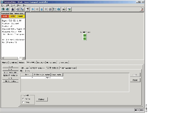
Provision Card FEC Thresholds
Step 1
(In this example, other transponder and muxponder cards are also applicable, such as TXP_MR_10G, TXPP_MR_2.5G, and MXP_2.5G_10G.)Step 2
Figure 1-47 Provision Card FEC Thresholds
Step 3
Step 4
1.7.7 Sample Trouble Resolutions
Some sample trouble resolutions using performance monitoring and TCAs for isolating points of degrade are provided below.
Symptom There is a BBE TCA on a single transponder pair.
Possible Cause The transponder input power is out of range.
Recommended Action Check the input power on the transponder. It should be within the specified/supported range.
Possible Cause There are dirty trunk connectors on the transponder.
Recommended Action Check the connector on the trunk port.
Possible Cause There is a degraded trunk patch-cord between the transponder and the DWDM port.
Recommended Action Check the patch-cord on the transponder DWDM port.
Possible Cause There are dirty client connectors on the channel add-drop (ADxC) transmit port or the demultiplexer (DMX) has crossed the near-end TCA.
Recommended Action Check the connector on the OCH port of the ADxC.
Possible Cause There are dirty client connectors on the ADxC receive port or the multiplexer (MUX) has crossed the far-end TCA point.
Recommended Action If an optical channel bypass exists along the line, check the connectors.
Symptom There is a BBE TCA on all transponders connected to a band add-drop card (ADxB).
Possible Cause The transponder input power is out of range.
Recommended Action Check the input power on the transponder. It should be within the specified/supported range.
Possible Cause There is a dirty connector on the 4MD port.
Recommended Action Check the connector on the drop port of the ADxB.
Possible Cause There is a dirty connector on the ADxB drop port, and it has crossed the near-end TCA point.
Recommended Action Check the connector on the drop port of the 4MD.
Possible Cause There is a dirty connector on the ADxB add port and it has crossed the far-end TCA.
Recommended Action Check the patch-cord on the 4MD or AD1Bx.
Possible Cause There is a degraded patch-cord between the ADxB and the 4MD.
Recommended Action If an optical band bypass exists along the line, check the band connectors.
Symptom There is a BBE TCA on all transponders which the OCH passes through a single OTS section.
Possible Cause This is not a transponder or channel-related issue.
Recommended Action The problem is in the intercabinet signal path preceding the transponder. Refer to the Cisco ONS 15454 DWDM Installation and Operations Guide for more information about configurations and acceptance tests for this area
Symptom You have an LBC TCA on a single transponder.
Possible Cause The laser of the transponder is degrading.
Recommended Action The problem is within the laser circuitry. Check the OPT-PRE or OPT-BST optical amplifier cards. Refer to the Cisco ONS 15454 DWDM Installation and Operations Guide for more information about setting up these cards.
1.8 Using CTC Diagnostics
In Release 5.0, CTC provides diagnostics for the following functions:
•
•
•
•
•
•
Some of these functions, such as ASIC verification and standby card operation, are invisibly monitored in background functions. Change or problem notifications are provided in the Alarms and Conditions window. Other diagnostic functions—verifying card LED function, creating bidirectional diagnostic circuits, and also downloading diagnostic files for technical support—are available to the user in the node view Maintenance > Diagnostic tab. The user-operated diagnostic features are described in the following paragraphs.
1.8.1 Card LED Lamp Tests
A card LED lamp test determines whether card-level indication LEDs are operational. This diagnostic test is run as part of the initial ONS 15454 turn-up, during maintenance routines, or any time you question whether an LED is in working order. Maintenance or higher-level users can complete the following tasks to verify LED operation.
Verify General Card LED Operation
Step 1
Figure 1-48 CTC Node View Diagnostic Window
Step 2
Step 3
•
•
•
Step 4
With the exceptions previously described, if an OC-N or DS-N LED does not light up, the LED is faulty. Return the defective card to Cisco through the RMA process. Contact Cisco Technical Support (1 800 553-2447).
Verify G-Series Ethernet or FC_MR-4 Card Port-Level LED Operation
Note
Step 1
Step 2
•
•
•
Step 3
Verify E-Series and ML-Series Ethernet Card Port-Level LED Operation
Note
Note
Step 1
Step 2
•
•
•
Step 3
1.8.2 Retrieve Diagnostics File Button
When you click the Retrieve Diagnostics File button in the Maintenance window, CTC retrieves system data that can be off-loaded by a Maintenance or higher-level user to a local directory and sent to Technical Support for troubleshooting purposes. The diagnostics file is in machine language and is not human-readable, but can be used by Cisco Technical Support for problem analysis. Complete the following task to off-load the diagnostics file.
Note
Off-Load the Diagnostics File
Step 1
Step 2
Step 3
Step 4
You do not have to give the archive file a particular extension. It is readable in any application that supports text files, such as WordPad, Microsoft Word (imported), etc.
Step 5
The Get Diagnostics status window shows a progress bar indicating the percentage of the file being saved, then shows "Get Diagnostics Complete."
Step 6
1.8.3 Bidirectional Diagnostic Circuit
In Release 5.0, CTC provides a diagnostic bidirectional loopback circuit feature that uses pseudo-random bit sequence (PRBS) error detection to monitor standby path protection, BLSR, 1+1, or unprotected circuit path readiness.
The diagnostic circuit is bidirectional and uses a single VT 1.5 in an STS. The circuit can traverse multiple nodes, but it must be carried by the same STS for the entire path. The circuit originates and ultimately destinates on the same node, but can be looped (by a hairpin circuit) through other nodes. Once the circuit returns to the originating node, the signal result is detected and analyzed for errors by PRBS.
This type of circuit is created much the same way as a normal standby protection channel access (PCA) circuit, but is designated by checking the Diagnostic check box during circuit creation. A normal circuit uses line cards as the endpoints, but if a circuit is configured as a diagnostic, the endpoints are cross-connect cards.
Each card type utilizes the diagnostic feature differently. Standby electrical cards run PRBS tests to ensure signal path integrity. Optical cards do not run PRBS tests, but instead run ASIC tests to test card operability. Cross-connect cards verify the standby paths.
The diagnostic circuit can be configured for an end-to-end or multiple-node path layout, traversing the transmit and receive standby paths as shown in Figure 1-49.
Figure 1-49 CTC Node View Diagnostic Window
In Release 5.0, the maximum diagnostic circuit size is VT1.5, and the maximum quantity of available diagnostic circuits is one per node. (In other words, if you create a diagnostic VT within an STS, the remaining 27 VTs can still be provisioned, and they may also contain diagnostic circuits originating on other nodes.)
As with all bidirectional circuits, a diagnostic circuit can only be created if the same STS is available on each span the circuit traverses. When you use a bidirectional diagnostic that traverses one or more intermediate nodes, create or utilize an existing bidirectional circuit on each intermediate node. At the terminating node, you will need to create a hairpin loopback at the end of the PRBS source span to return the signal.
Note
Create a Bidirectional Diagnostic Circuit
Step 1
Step 2
Step 3
Step 4
Step 5
•
•
•
Step 6
Step 7
Figure 1-50 Network View Circuit Creation Dialog Box
•
•
•
•
•
•
•
•
•
Step 8
Step 9
a.
b.
c.
Step 10
a.
b.
c.
d.
e.
Step 11
Step 12
Stop. You have completed this procedure.
1.9 Restoring the Database and Default Settings
This section contains troubleshooting for node operation errors that require restoration of software data or the default node setup.
1.9.1 Restore the Node Database
Symptom One or more nodes are not functioning properly or have incorrect data.
Possible Cause There is an incorrect or corrupted node database.
Recommended Action Perform a Restore the Database procedure. Refer to the "Restore the Database" procedure.
Restore the Database
Caution
Caution
Caution
Note
Note
Step 1
a.
b.
A Java Console window displays the CTC file download status. The web browser displays information about your Java and system environments. If this is the first login from this computer, CTC caching messages appear while CTC files are downloaded to your computer. The first time you connect to an ONS 15454, this process can take several minutes. After the download, the CTC Login dialog box appears.
c.
Step 2
Step 3
a.
b.
Step 4
Step 5
Step 6
Note
Step 7
Step 8
Step 9
The Restore Database dialog box monitors the file transfer.
Step 10
Step 11
Step 12
1.9.2 Restore the Node to Factory Configuration
Symptom A node has both TCC2/TCC2P cards in standby state, and you are unable reset the TCC2/TCC2P cards to make the node functional.
Possible Cause Both TCC2/TCC2P cards are failing in the node.
Possible Cause You are replacing both TCC2/TCC2P cards at the same time.
Recommended Action Restore the node to factory configuration. Refer to the "Use the Reinitialization Tool to Clear the Database and Upload Software (Windows)" procedure or the "Use the Reinitialization Tool to Clear the Database and Upload Software (UNIX)" procedure as required.
Caution
Caution
Caution
Caution
Caution
Note
Note
Note
Use the Reinitialization Tool to Clear the Database and Upload Software (Windows)
Caution
Caution
Note
Step 1
Step 2
Step 3
Step 4
Figure 1-51 Reinitialization Tool in Windows
Step 5
Step 6
Step 7
Step 8
Step 9
Note
Step 10
Caution
Step 11
Step 12
Step 13
Note
Step 14
Step 15
Use the Reinitialization Tool to Clear the Database and Upload Software (UNIX)
Caution
Caution
Note
Note
Step 1
Step 2
Step 3
Figure 1-52 Reinitialization Tool in UNIX
Step 4
Step 5
Step 6
Step 7
Step 8
Step 9
Caution
Step 10
Step 11
Step 12
Note
Step 13
Step 14
1.10 PC Connectivity Troubleshooting
This section contains information about system minimum requirements, supported platforms, browsers, and JREs for R5.0, and troubleshooting procedures for PC and network connectivity to the ONS 15454.
1.10.1 PC System Minimum Requirements
Workstations running CTC R5.0 for the ONS products on Windows platforms need to have the following minimum requirements:
•
•
•
•
•
1.10.2 Sun System Minimum Requirements
Workstations running CTC R5.0 for the ONS products on Sun workstations need to have the following minimum requirements:
•
•
•
1.10.3 Supported Platforms, Browsers, and JREs
Software R5.0 CTC supports the following platforms:
•
•
•
•
•
•
Software R5.0 CTC supports the following browsers and JREs:
•
•
•
Note
Netscape: http://channels.netscape.com/ns/browsers/default.jsp
Internet Explorer: http://www.microsoft.com
Note
Note
1.10.4 Unsupported Platforms and Browsers
Software R5.0 does not support the following platforms:
•
•
•
Software R5.0 does not support the following browsers and JREs:
•
•
•
1.10.5 Unable to Verify the IP Configuration of Your PC
Symptom When connecting your PC to the ONS 15454, you are unable to successfully ping the IP address of your PC to verify the IP configuration.
Possible Cause The IP address was entered incorrectly.
Recommended Action Verify that the IP address used to ping the PC matches the IP address displayed when in the Windows IP Configuration information retrieved from the system. See the "Verify the IP Configuration of Your PC" procedure.
Possible Cause The IP configuration of your PC is not properly set.
Recommended Action Verify the IP configuration of your PC. Complete the "Verify the IP Configuration of Your PC" procedure. If this procedure is unsuccessful, contact your Network Administrator for instructions to correct the IP configuration of your PC.
Verify the IP Configuration of Your PC
Step 1
Step 2
Step 3
•
The Windows IP configuration information appears, including the IP address, subnet mask, and the default gateway.
Note
Step 4
Step 5
If the DOS window returns multiple (usually four) replies, the IP configuration is working properly.
If you do not receive a reply, your IP configuration might not be properly set. Contact your Network Administrator for instructions to correct the IP configuration of your PC.
1.10.6 Browser Login Does Not Launch Java
Symptom The message "Loading Java Applet" does not appear and the JRE does not launch during the initial login.
Possible Cause The PC operating system and browser are not properly configured.
Recommended Action Reconfigure the PC operating system java plug-in control panel and the browser settings. Complete the "Reconfigure the PC Operating System Java Plug-in Control Panel" procedure and the "Reconfigure the Browser" procedure.
Reconfigure the PC Operating System Java Plug-in Control Panel
Step 1
Step 2
a.
b.
c.
d.
Step 3
Step 4
Step 5
Step 6
Step 7
Step 8
Step 9
Reconfigure the Browser
Step 1
Step 2
a.
b.
c.
d.
e.
f.
•
•
g.
h.
i.
Step 3
a.
b.
c.
d.
Step 4
Step 5
Step 6
1.10.7 Unable to Verify the NIC Connection on Your PC
Symptom When connecting your PC to the ONS 15454, you are unable to verify that the network interface card (NIC) connection is working properly because the link LED is not illuminated or flashing.
Possible Cause The Category-5 cable is not plugged in properly.
Recommended Action Confirm that both ends of the cable are properly inserted. If the cable is not fully inserted due to a broken locking clip, the cable should be replaced.
Possible Cause The Category-5 cable is damaged.
Recommended Action Ensure that the cable is in good condition. If in doubt, use a known-good cable. Often, cabling is damaged due to pulling or bending. (For information about installing cable, refer to the Cisco ONS 15454 Procedure Guide Chapter 2, "Install Cards and Fiber-Optic Cable.")
Possible Cause Incorrect type of Category-5 cable is being used.
Recommended Action If connecting an ONS 15454 directly to your laptop, a PC, or a router, use a straight-through Category-5 cable. When connecting the ONS 15454 to a hub or a LAN switch, use a crossover Category-5 cable. For details on the types of Category-5 cables, see the "Crimp Replacement LAN Cables" section.
Possible Cause The NIC is improperly inserted or installed.
Recommended Action If you are using a Personal Computer Memory Card International Association (PCMCIA)-based NIC, remove and reinsert the NIC to make sure the NIC is fully inserted. (If the NIC is built into the laptop or PC, verify that the NIC is not faulty.)
Possible Cause The NIC is faulty.
Recommended Action Confirm that the NIC is working properly. If you have no issues connecting to the network (or any other node), then the NIC should be working correctly. If you have difficulty connecting a to the network (or any other node), then the NIC might be faulty and needs to be replaced.
1.10.8 Verify PC Connection to the ONS 15454 (ping)
Symptom The TCP/IP connection was established and then lost.
Possible Cause A lost connection between the PC and the ONS 15454.
Recommended Action Use a standard ping command to verify the TCP/IP connection between the PC and the ONS 15454 TCC2/TCC2P card. A ping command should work if the PC connects directly to the TCC2/TCC2P card or uses a LAN to access the TCC2/TCC2P card. Complete the "Ping the ONS 15454" procedure.
Ping the ONS 15454
Step 1
a.
b.
Step 2
ping ONS-15454-IP-addressFor example:
ping 198.168.10.10Step 3
Step 4
Step 5
Step 6
1.10.9 The IP Address of the Node is Unknown
Symptom The IP address of the node is unknown and you are unable to login.
Possible Cause The node is not set to the default IP address.
Recommended Action Leave one TCC2/TCC2P card in the shelf. Connect a PC directly to the remaining TCC2/TCC2P card and perform a hardware reset of the card. The TCC2/TCC2P card transmits the IP address after the reset to enable you to capture the IP address for login. Complete the "Retrieve Unknown Node IP Address" procedure.
Retrieve Unknown Node IP Address
Step 1
Step 2
Step 3
Step 4
1.11 CTC Operation Troubleshooting
This section contains troubleshooting procedures for CTC login or operation problems.
1.11.1 CTC Colors Do Not Appear Correctly on a UNIX Workstation
Symptom When running CTC on a UNIX workstation, the colors do not appear correctly. For example, both major and minor alarms appear in the same color.
Possible Cause When running in 256-color mode on a UNIX workstation, color-intensive applications such as Netscape might use all of the colors.
Recommended Action CTC requires a full 24-color palette to run properly. When logging into CTC on a UNIX workstation, run as many colors as your adapter will support. In addition, you can use the -install or the -ncols 32 command line options to limit the number of colors that Netscape uses. Complete the "Limit Netscape Colors" procedure. If the problem persists after limiting Netscape colors, exit any other color-intensive applications in use.
Limit Netscape Colors
Step 1
Step 2
netscape -install (installs Netscape colors for Netscape use)
or
netscape -ncols 32 (limits Netscape to 32 colors so that if the requested color is not available, Netscape chooses the closest color option)
1.11.2 Unable to Launch CTC Help After Removing Netscape
Symptom After removing Netscape and running CTC using Internet Explorer, you are unable to launch CTC Help and receive an "MSIE is not the default browser" error message.
Possible Cause Loss of association between browser and Help files.
Recommended Action When the CTC software and Netscape are installed, the Help files are associated with Netscape by default. When you remove Netscape, the Help files are not automatically associated with Internet Explorer as the default browser. Reset Internet Explorer as the default browser so that CTC associates the Help files to the correct browser. Complete the "Reset Internet Explorer as the Default Browser for CTC" procedure to associate the CTC Help files to the correct browser.
Reset Internet Explorer as the Default Browser for CTC
Step 1
Step 2
Step 3
Step 4
Step 5
Step 6
Step 7
1.11.3 Unable to Change Node View to Network View
Symptom When activating a large, multinode BLSR from Software R3.2 to Software R3.3, some of the nodes appear grayed out. Logging into the new CTC, the user is unable to change node view to network view on any and all nodes, from any workstation. This is accompanied by an "Exception occurred during event dispatching: java.lang.OutOfMemoryError" in the java window.
Possible Cause The large, multinode BLSR requires more memory for the graphical user interface (GUI) environment variables.
Recommended Action Reset the system or user CTC_HEAP environment variable to increase the memory limits. Complete the "Set the CTC_HEAP and CTC_MAX_PERM_SIZE_HEAP Environment Variables for Windows" procedure or the "Set the CTC_HEAP and CTC_MAX_PERM_SIZE_HEAP Environment Variables for Solaris" procedure to enable the CTC_HEAP variable change.
Note
Set the CTC_HEAP and CTC_MAX_PERM_SIZE_HEAP Environment Variables for Windows
Note
Step 1
Step 2
Step 3
Step 4
Step 5
Step 6
CTC_HEAPin the Variable Name field.Step 7
512in the Variable Value field, and then click the OK button to create the variable.Step 8
Step 9
CTC_MAX_PERM_SIZE_HEAPin the Variable Name field.Step 10
128in the Variable Value field, and then click the OK button to create the variable.Step 11
Step 12
Set the CTC_HEAP and CTC_MAX_PERM_SIZE_HEAP Environment Variables for Solaris
Step 1
Step 2
Example
The following example shows how to set the environment variables in the C shell:
% setenv CTC_HEAP 512% setenv CTC_MAX_PERM_SIZE_HEAP 1281.11.4 Browser Stalls When Downloading CTC JAR Files From TCC2/TCC2P
Symptom The browser stalls or hangs when downloading a CTC Java archive (JAR) file from the TCC2/TCC2P card.
Possible Cause McAfee VirusScan software might be interfering with the operation. The problem occurs when the VirusScan Download Scan is enabled on McAfee VirusScan 4.5 or later.
Recommended Action Disable the VirusScan Download Scan feature. Complete the "Disable the VirusScan Download Scan" procedure.
Disable the VirusScan Download Scan
Step 1
Step 2
Step 3
Step 4
Step 5
Step 6
Step 7
Step 8
Step 9
1.11.5 CTC Does Not Launch
Symptom CTC does not launch; usually an error message appears before the login window appears.
Possible Cause The Netscape browser cache might point to an invalid directory.
Recommended Action Redirect the Netscape cache to a valid directory. Complete the "Redirect the Netscape Cache to a Valid Directory" procedure.
Redirect the Netscape Cache to a Valid Directory
Step 1
Step 2
Step 3
Step 4
Step 5
The cache file location is usually C:\ProgramFiles\Netscape\Users\yourname\cache. The yourname segment of the file location is often the same as the user name.
1.11.6 Slow CTC Operation or Login Problems
Symptom You experience slow CTC operation or have problems logging into CTC.
Table 1-3 describes the potential cause of the symptom and the solution.
Table 1-3 Slow CTC Operation or Login Problems
The CTC cache file might be corrupted or might need to be replaced.
Search for and delete cache files. This operation forces the Cisco ONS 15454 to download a new set of Java archive (JAR) files to your computer hard drive. Complete the "Delete the CTC Cache File Automatically" procedure or the "Delete the CTC Cache File Manually" procedure.
Insufficient heap memory allocation.
Increase the heap size if you are using CTC to manage more than 50 nodes concurrently. See the "Set the CTC_HEAP and CTC_MAX_PERM_SIZE_HEAP Environment Variables for Windows" procedure or the "Set the CTC_HEAP and CTC_MAX_PERM_SIZE_HEAP Environment Variables for Solaris" procedure.
Note
Delete the CTC Cache File Automatically
Caution
Step 1
Step 2
Step 3
Figure 1-53 Deleting the CTC Cache
Delete the CTC Cache File Manually
Caution
Step 1
Step 2
Step 3
Step 4
Step 5
1.11.7 Node Icon is Gray on CTC Network View
Symptom The CTC network view shows one or more node icons as gray in color and without a node name.
Possible Cause Different CTC releases do not recognize each other.
Recommended Action Correct the core version build as described in the "Different CTC Releases Do Not Recognize Each Other" section.
Possible Cause Username and password do not match.
Recommended Action Correct the username and password as described in the "Username or Password Do Not Match" section.
Possible Cause No IP connectivity between nodes.
Recommended Action Usually accompanied by Ethernet-specific alarms. Verify the Ethernet connections as described in the "Ethernet Connections" section.
Possible Cause A lost DCC connection.
Recommended Action Usually accompanied by an embedded operations channel (EOC) alarm. Clear the EOC alarm and verify the DCC connection as described in the "EOC" alarm.
1.11.8 CTC Cannot Launch Due to Applet Security Restrictions
Symptom The error message "Unable to launch CTC due to applet security restrictions" appears after you enter the IP address in the browser window.
Possible Cause You are logging into a node running CTC Software R4.0 or earlier. Releases earlier than R4.1 require a modification to the java.policy file so that CTC JAR files can be downloaded to the computer. The modified java.policy file might not exist on the computer.
Recommended Action Install the software CD for the release of the node you are logging into. Run the CTC Setup Wizard (double-click Setup.exe). Choose Custom installation, then choose the Java Policy option. For additional information, refer to the CTC installation information in the Cisco ONS 15454 Procedure Guide Chapter 3, "Connect the PC and Log into the GUI." If the software CD is not available, you must manually edit the java.policy file on your computer. Complete the "Manually Edit the java.policy File" procedure.
Manually Edit the java.policy File
Step 1
Step 2
// Insert this into the system-wide or a per-user java.policy file.// DO NOT OVERWRITE THE SYSTEM-WIDE POLICY FILE--ADD THESE LINES!grant codeBase "http://*/fs/LAUNCHER.jar {permission java.security.AllPermission;};Step 3
Step 4
CTC should now start correctly.
Step 5
1.11.9 Java Runtime Environment Incompatible
Symptom The CTC application does not run properly.
Possible Cause The compatible Java 2 JRE is not installed.
Recommended Action The JRE contains the Java virtual machine, runtime class libraries, and Java application launcher that are necessary to run programs written in the Java programming language. The ONS 15454 CTC is a Java application. A Java application, unlike an applet, cannot rely completely on a web browser for installation and runtime services. When you run an application written in the Java programming language, you need the correct JRE installed. The correct JRE for each CTC software release is included on the Cisco ONS 15454 software CD and on the Cisco ONS 15454 documentation CD. Complete the "Launch CTC to Correct the Core Version Build" procedure. If you are running multiple CTC software releases on a network, the JRE installed on the computer must be compatible with the different software releases. Table 1-4 shows JRE compatibility with ONS 15454 software releases.
Launch CTC to Correct the Core Version Build
Step 1
Step 2
Step 3
Step 4
Note
1.11.10 Different CTC Releases Do Not Recognize Each Other
Symptom Different CTC releases do not recognize each other. This situation is often accompanied by the INCOMPATIBLE-SW alarm.
Possible Cause The software loaded on the connecting workstation and the software on the TCC2/TCC2P card are incompatible.
Recommended Action This occurs when the TCC2/TCC2P software is upgraded but the PC has not yet upgraded the compatible CTC JAR file. It also occurs on login nodes with compatible software that encounter other nodes in the network that have a newer software version. Complete the "Launch CTC to Correct the Core Version Build" procedure.
Note
Launch CTC to Correct the Core Version Build
Step 1
Step 2
Step 3
Step 4
Note
1.11.11 Username or Password Do Not Match
Symptom A username/password mismatch often occurs concurrently with a NOT-AUTHENTICATED alarm.
Possible Cause The username or password entered does not match the information stored in the TCC2/TCC2P.
Recommended Action All ONS nodes must have the same username and password created to display every ONS node in the network. You can also be locked out of certain ONS nodes on a network if your username and password were not created on those specific ONS nodes. For initial login to the ONS 15454, enter the CISCO15 username in capital letters and type otbu+1 in lower-case letters. Click Login. (In Release 5.0, a password is required.) If you are using a CTC Software R2.2.2 or earlier and CISCO15 does not work, enter cerent454 for the user name. Complete the "Verify Correct Username and Password" procedure.
Verify Correct Username and Password
Step 1
Step 2
Step 3
1.11.12 No IP Connectivity Exists Between Nodes
Symptom No IP connectivity exists between nodes. The nodes have a gray icon. This problem is usually accompanied by alarms.
Possible Cause A lost Ethernet connection.
Recommended Action Usually is accompanied by Ethernet-specific alarms. Verify the Ethernet connections as described in the "Ethernet Connections" section.
1.11.13 DCC Connection Lost
Symptom DCC connection is lost. The node usually has alarms and the nodes in the network view have a gray icon. This symptom is usually accompanied by an EOC alarm.
Possible Cause A lost DCC connection.
Recommended Action Usually accompanied by an EOC alarm. Clear the EOC alarm and verify the DCC connection as described in the "EOC" alarm.
1.11.14 "Path in Use" Error When Creating a Circuit
Symptom While creating a circuit, you get a "Path in Use" error that prevents you from completing the circuit creation.
Possible Cause Another user has already selected the same source port to create another circuit.
Recommended Action CTC does not remove a card or port from the available list until a circuit is completely provisioned. If two users simultaneously select the same source port to create a circuit, the first user to complete circuit provisioning gets use of the port. The other user gets the "Path in Use" error. Cancel the circuit creation and start over, or click Back until you return to the initial circuit creation window. The source port that was previously selected no longer appears in the available list because it is now part of a provisioned circuit. Select a different available port and begin the circuit creation process again.
1.11.15 Calculate and Design IP Subnets
Symptom You cannot calculate or design IP subnets on the ONS 15454.
Possible Cause The IP capabilities of the ONS 15454 require specific calculations to properly design IP subnets.
Recommended Action Cisco provides a free online tool to calculate and design IP subnets. Go to http://www.cisco.com/techtools/ip_addr.html. For information about ONS 15454 IP capability, refer to the Cisco ONS 15454 Reference Manual Chapter 12, "IP Networking."
1.11.16 Ethernet Connections
Symptom Ethernet connections appear to be broken or are not working properly.
Possible Cause Improperly seated connections.
Possible Cause Incorrect connections.
Recommended Action You can fix most connectivity problems in an Ethernet network by following a few guidelines. See Figure 1-54 when using the steps in the "Verify Ethernet Connections" procedure.
Figure 1-54 Ethernet Connectivity Reference
Verify Ethernet Connections
Step 1
Step 2
Step 3
Step 4
Step 5
Step 6
a.
b.
c.
d.
e.
Step 7
a.
b.
c.
Step 8
Step 9
1.11.17 VLAN Cannot Connect to Network Device from Untag Port
Symptom Networks that have a VLAN with one ONS 15454 Ethernet card port set to Tagged and one ONS 15454 Ethernet card set to Untag might have difficulty implementing Address Resolution Protocol (ARP) for a network device attached to the Untag port ( Figure 1-55). They might also see a higher than normal runt packets count at the network device attached to the Untag port. This symptom/limitation also exists when ports within the same card or ports within the same chassis are put on the same VLAN, with a mix of tagged and untagged.
Possible Cause The Tagged ONS 15454 adds the IEEE 802.1Q tag and the Untag ONS 15454 removes the Q-tag without replacing the bytes. The NIC of the network device categorizes the packet as a runt and drops the packet.
Possible Cause Dropped packets can also occur when ARP attempts to match the IP address of the network device attached to the Untag port with the physical MAC address required by the network access layer.
Recommended Action The solution is to set both ports in the VLAN to Tagged to stop the stripping of the 4 bytes from the data packet and prevent the NIC card in the network access device from recognizing the packet as a runt and dropping it. Network devices with IEEE 802.1Q-compliant NIC cards accept the tagged packets. Network devices with non IEEE 802.1Q compliant NIC cards still drop these tagged packets. The solution might require upgrading network devices with non-IEEE 802.1Q compliant NIC cards to IEEE 802.1Q compliant NIC cards. You can also set both ports in the VLAN to Untag, but you will lose IEEE 802.1Q compliance.
Figure 1-55 VLAN with Ethernet Ports at Tagged and Untag
Change VLAN Port Tag and Untagged Settings
Step 1
Step 2
Figure 1-56 Configuring VLAN Membership for Individual Ethernet Ports
Step 3
Step 4
Note
Step 5
1.12 Circuits and Timing
This section provides solutions to circuit creation and reporting errors, as well as common timing reference errors and alarms.
1.12.1 OC-N Circuit Transitions to Partial State
Symptom An automatic or manual transition of a circuit from one state to another state results in the OOS-PARTIAL status, which indicates that not all OC-N connections in the circuit are in the IS-NR service state.
Possible Cause During a manual transition, CTC cannot communicate with one of the nodes or one of the nodes is on a version of software that does not support the new state model.
Recommended Action Repeat the manual transition operation. If the partial state persists, determine which node in the circuit is not changing to the desired state. Complete the "View the State of OC-N Circuit Nodes" procedure. Log into the circuit node that did not change to the desired state and determine the version of software. If the software on the node is Software R3.3 or earlier, upgrade the software. Refer to the Cisco ONS 15454 Software Upgrade Guide for software upgrade procedures.
Note
Possible Cause During an automatic transition, some path-level defects and/or alarms were detected on the circuit.
Possible Cause One end of the circuit is not properly terminated.
Recommended Action Determine which node in the circuit is not changing to the desired state. Complete the "View the State of OC-N Circuit Nodes" procedure. Log onto the circuit node that did not change to the desired state and examine the circuit for path-level defects, improper circuit termination, or alarms. Refer to Chapter 2, "Alarm Troubleshooting," for procedures to clear alarms. Refer to the Cisco ONS 15454 Procedure Guide Chapter 9, "Manage Circuits," for instructions to change circuit configuration settings. Resolve and clear the defects and/or alarms on the circuit node and verify that the circuit transitions to the desired state.
View the State of OC-N Circuit Nodes
Step 1
Step 2
Step 3
Step 4
The State tab window lists the Node, End A, End B, CRS Admin State, and CRS Service State for each of the nodes in the circuit.
1.12.2 AIS-V on DS3XM-6 or DS3XM-12 Unused VT Circuits
Symptom An incomplete circuit path causes an AIS.
Possible Cause The port on the reporting node is in-service but a node upstream on the circuit does not have an OC-N port in service.
Recommended Action An AIS-V indicates that an upstream failure occurred at the virtual tributary (VT) layer. AIS-V alarms also occur on DS3XM-6 VT circuits that are not carrying traffic and on stranded bandwidth. Complete the "Clear AIS-V on DS3XM-6 or DS3XM-12 Unused VT Circuits" procedure.
Clear AIS-V on DS3XM-6 or DS3XM-12 Unused VT Circuits
Step 1
Step 2
Step 3
Step 4
Step 5
Step 6
Step 7
Step 8
Step 9
Step 10
Step 11
Step 12
Step 13
Step 14
Step 15
Step 16
1.12.3 Circuit Creation Error with VT1.5 Circuit
Symptom You receive an "Error while finishing circuit creation. Unable to provision circuit. Unable to create connection object at node_name" message when trying to create a VT1.5 circuit in CTC.
Possible Cause You might have run out of bandwidth on the VT cross-connect matrix at the ONS 15454 indicated in the error message.
Recommended Action The matrix has a maximum capacity of 336 bidirectional VT1.5 cross-connects. Certain configurations exhaust VT capacity with less than 336 bidirectional VT1.5s in a BLSR or less than 224 bidirectional VT1.5s in a path protection or 1+1 protection group. Refer to the Cisco ONS 15454 Reference Manual for more information.
1.12.4 Unable to Create Circuit From DS-3 Card to DS3XM-6 or DS3XM-12 Card
Symptom You cannot create a circuit from a DS-3 card to a DS3XM-6 or DS3XM-12 card.
Possible Cause A DS-3 card and a DS3XM-6 or DS3XM-12 card have different functions.
Recommended Action A DS3XM-6 card converts each of its six DS-3 interfaces into 28 DS-1s for cross-connection through the network. The DS3XM-12 converts each of its 12 interfaces into up to 48 DS-1s. Thus, you can create a circuit from a DS3XM-6 or DS3XM-12 card to a DS-1 card, but not from a DS3XM card to a DS-3 card. These differences are evident in the STS path overhead. The DS-3 card uses asynchronous mapping for DS-3, which is indicated by the C2 byte in the STS path overhead that has a hex code of 04. A DS3XM-6 or DS3XM-12 has a VT payload with a C2 hex value of 02.
Note
1.12.5 DS-3 Card Does Not Report AIS-P From External Equipment
Symptom A DS3-12, DS3N-12, DS3-12E, or DS3N-12E card does not report STS AIS-P from the external equipment/line side.
Possible Cause The card is functioning as designed.
Recommended Action This card terminates the port signal at the backplane so STS AIS-P is not reported from the external equipment/line side. DS3-12, DS3N-12, DS3-12E, and DS3N-12E cards have DS3 header monitoring functionality, which allows you to view PM on the DS3 path. Nevertheless, you cannot view AIS-P on the STS path. For more information about the PM capabilities of the DS3-12, DS3N-12, DS3-12E or DS3N-12E cards, go to Chapter 4, "Performance Monitoring."
1.12.6 OC-3 and DCC Limitations
Symptom Limitations to OC-3 and DCC usage.
Possible Cause OC-3 and DCC have limitations for the ONS 15454.
Recommended Action For an explanation of OC-3 and DCC limitations, refer to the DCC Tunnels section of the Cisco ONS 15454 Procedure Guide Chapter 5, "Turn Up Network."
1.12.7 ONS 15454 Switches Timing Reference
Symptom Timing references switch when one or more problems occur.
Possible Cause The optical or BITS input is receiving loss of signal (LOS), loss of frame (LOF), or AIS alarms from its timing source.
Possible Cause The optical or building integrated timing supply (BITS) input is not functioning.
Possible Cause The synchronization status messaging (SSM) message is set to do not use for synchronization (DUS).
Possible Cause SSM indicates a Stratum 3 or lower clock quality.
Possible Cause The input frequency is off by more than 15 ppm.
Possible Cause The input clock wanders and has more than three slips in 30 seconds.
Possible Cause A bad timing reference existed for at least two minutes.
Recommended Action The ONS 15454 internal clock operates at a Stratum 3E level of accuracy. This gives the ONS 15454 a free-running synchronization accuracy of +/- 4.6 ppm and a holdover stability of less than 255 slips in the first 24 hours or 3.7 x 10⁻⁷/day, including temperature. ONS 15454 free-running synchronization relies on the Stratum 3 internal clock. Over an extended time period, using a higher quality Stratum 1 or Stratum 2 timing source results in fewer timing slips than a lower quality Stratum 3 timing source.
1.12.8 Holdover Synchronization Alarm
Symptom The clock is running at a different frequency than normal and the "HLDOVRSYNC" alarm appears.
Possible Cause The last reference input has failed.
Recommended Action The clock is running at the frequency of the last known-good reference input. This alarm is raised when the last reference input fails. See the "HLDOVRSYNC" alarm on page 2-125 for a detailed description.
Note
1.12.9 Free-Running Synchronization Mode
Symptom The clock is running at a different frequency than normal and the "FRNGSYNC" alarm appears.
Possible Cause No reliable reference input is available.
Recommended Action The clock is using the internal oscillator as its only frequency reference. This occurs when no reliable, prior timing reference is available. See the "FRNGSYNC" condition on page 2-112 for a detailed description.
1.12.10 Daisy-Chained BITS Not Functioning
Symptom You are unable to daisy chain the BITS sources.
Possible Cause Daisy-chained BITS sources are not supported on the ONS 15454.
Recommended Action Daisy-chained BITS sources cause additional wander buildup in the network and are therefore not supported. Instead, use a timing signal generator to create multiple copies of the BITS clock and separately link them to each ONS 15454.
1.12.11 Blinking STAT LED after Installing a Card
Symptom After installing a card, the STAT LED blinks continuously for more than 60 seconds.
Possible Cause The card cannot boot because it failed the Power On Shelf Test (POST) diagnostics.
Recommended Action The blinking STAT LED indicates that POST diagnostics are being performed. If the LED continues to blink more than 60 seconds, the card has failed the POST diagnostics test and has failed to boot. If the card has truly failed, an "EQPT" alarm is raised against the slot number with an "Equipment Failure" description. Check the alarm tab for this alarm to appear for the slot where the card was installed. To attempt recovery, remove and reinstall the card and observe the card boot process. If the card fails to boot, replace the card. Complete the "Physically Replace a Traffic Card" procedure on page 2-271.
Caution
1.13 Fiber and Cabling
This section explains problems typically caused by cabling connectivity errors. It also includes instructions for crimping Category-5 cable and lists the optical fiber connectivity levels.
1.13.1 Bit Errors Appear for a Traffic Card
Symptom A traffic card has multiple bit errors.
Possible Cause Faulty cabling or low optical-line levels.
Recommended Action Bit errors on line (traffic) cards usually originate from cabling problems or low optical-line levels. The errors can be caused by synchronization problems, especially if pointer justification (PJ) errors are reported. Moving cards into different error-free slots will isolate the cause. Use a test set whenever possible because the cause of the errors could be external cabling, fiber, or external equipment connecting to the ONS 15454. Troubleshoot low optical levels using the "Faulty Fiber-Optic Connections" section.
1.13.2 Faulty Fiber-Optic Connections
Symptom A line card has multiple SONET/DWDM alarms and/or signal errors.
Possible Cause Faulty fiber-optic connections.
Recommended Action Faulty fiber-optic connections can be the source of SONET/DWDM alarms and signal errors. Complete the "Verify Fiber-Optic Connections" procedure.
Possible Cause Faulty Category-5 cables.
Recommended Action Faulty Category-5 cables can be the source of SONET/DWDM alarms and signal errors. Complete the "Crimp Replacement LAN Cables" section.
Possible Cause Faulty GBICs.
Recommended Action Faulty GBICs can be the source of SONET/DWDM alarms and signal errors. See the "Replace Faulty GBIC or SFP Connectors" section.
Warning
Warning
Verify Fiber-Optic Connections
Step 1
Note
Step 2
Step 3
a.
b.
c.
d.
e.
Step 4
a.
b.
c.
IR cards transmit a lower output power than LR cards.
d.
Caution
e.
•
•
•
Note
Step 5
a.
b.
c.
d.
Caution
Step 6
LR cards transmit a higher output power than IR cards. When used with short runs of fiber, an LR transmitter is too powerful for the receiver on the receiving OC-N card.
Receiver overloads occur when maximum receiver power is exceeded.
Tip
Tip
1.13.2.1 Crimp Replacement LAN Cables
You can crimp your own LAN cables for use with the ONS 15454. Use a cross-over cable when connecting an ONS 15454 to a hub, LAN modem, or switch, and use a LAN cable when connecting an ONS 15454 to a router or workstation. Use Category-5 cable RJ-45 T-568B, Color Code (100 Mbps), and a crimping tool. Figure 1-57 shows the wiring of an RJ-45 connector. Figure 1-58 shows a LAN cable layout, and Table 1-5 shows the cable pinouts. Figure 1-59 shows a cross-over cable layout, and Table 1-6 shows the cross-over pinouts.
Figure 1-57 RJ-45 Pin Numbers
Figure 1-58 LAN Cable Layout
Figure 1-59 Cross-Over Cable Layout
Note
1.13.2.2 Replace Faulty GBIC or SFP Connectors
GBICs and Small Form-factor Pluggables (SFP) are hot-swappable and can be installed or removed while the card or shelf assembly is powered and running.
Warning
Warning
GBICs and SFPs are input/output devices that plug into a Gigabit Ethernet card to link the port with the fiber-optic network. The type of GBIC or SFP determines the maximum distance that the Ethernet traffic can travel from the card to the next network device. For a description of GBICs and SFPs and their capabilities refer to the "Ethernet Cards" chapter in the Cisco ONS 15454 Reference Manual.
Note
Note
GBICs are available in two different models. One GBIC model has two clips (one on each side of the GBIC) that secure the GBIC in the slot on the E1000-2-G, G-Series, or G1K-4 card. The other model has a locking handle. Both models are shown in Figure 1-60.
Figure 1-60 GBICs
For a list of available GBICs and SFPs for Ethernet cards and SAN (FC_MR-4) cards, refer to the Cisco ONS 15454 Reference Manual Chapter 5, "Ethernet Cards." For a list of available SFPs for TXP and MXP cards, refer to the Cisco ONS 15454 DWDM Installation and Operations Guide.
Note
Remove GBIC or SFP Connectors
Step 1
Warning
Step 2
Step 3
Installing a GBIC with Clips
Step 1
Step 2
Step 3
Step 4
Note
Figure 1-61 GBIC Installation (with Clips)
Step 5
Step 6
Step 7
Installing a GBIC with a Handle
Step 1
Step 2
Step 3
Step 4
Step 5
Note
Step 6
Step 7
1.13.3 OC-N Card Transmit and Receive Levels
Each OC-N card has a transmit and receive connector on its faceplate. Table 1-7 lists these levels.
1.14 Power Supply Problems
Symptom Loss of power or low voltage, resulting in a loss of traffic and causing the LCD clock to reset to the default date and time.
Possible Cause Loss of power or low voltage.
Possible Cause Improperly connected power supply.
Recommended Action The ONS 15454 requires a constant source of DC power to properly function. Input power is -48 VDC. Power requirements range from -42 VDC to -57 VDC. A newly installed ONS 15454 that is not properly connected to its power supply does not operate. Power problems can be confined to a specific ONS 15454 or affect several pieces of equipment on the site. A loss of power or low voltage can result in a loss of traffic and causes the LCD clock on the ONS 15454 to default to January 1, 1970, 00:04:15. To reset the clock, in node view click the Provisioning > General > General tab and change the Date and Time fields. Complete the "Isolate the Cause of Power Supply Problems" procedure.
Warning
Warning
Caution
Isolate the Cause of Power Supply Problems
Step 1
a.
b.
c.
d.
e.
f.
g.
h.
•
•
•
•
Step 2
a.
b.
c.
1.14.1 Power Consumption for Node and Cards
Symptom You are unable to power up a node or the cards in a node.
Possible Cause Improper power supply.
Recommended Action Refer to power information in the Cisco ONS 15454 Reference Manual Appendix A, "Hardware Specifications."
![]()
![]()
![]()
![]()
![]()
![]()
![]()
![]()
Posted: Tue Nov 27 07:55:57 PST 2007
All contents are Copyright © 1992--2007 Cisco Systems, Inc. All rights reserved.
Important Notices and Privacy Statement.