|
|

Table Of Contents
Applications and Configurations
Typcial IOF Node Configurations
Open-Ended Path Protection Circuit
Digital Cross-Connect Applications
Configuring ML-Series Cards for RPR
Wire Line Services (FCIP Over SONET)
Applications and Configurations
Note
The terms "Unidirectional Path Switched Ring" and "UPSR" may appear in Cisco literature. These terms do not refer to using Cisco ONS 15xxx products in a unidirectional path switched ring configuration. Rather, these terms, as well as "Path Protected Mesh Network" and "PPMN," refer generally to Cisco's path protection feature, which may be used in any topological network configuration. Cisco does not recommend using its path protection feature in any particular topological network configuration.
This chapter provides examples of common ONS 15454 Multi-Service Provisioning Platform (MSPP) network applications and shelf configurations. All SONET examples are shown as either ring or 1+1 protected. All DS-1, DS-3, and EC-1 examples are shown either as 1:N (N<5) or 1:1 protected. Ethernet cards are shown unprotected.
The examples shown in this chapter are designed to provide general guidance for creating ONS 15454 node configurations to meet your service needs.
The following topics are covered in this chapter:
•
Overview
The Cisco ONS 15454 Multi-Service Provisioning Platform (MSPP) combines the best of a traditional SONET TDM (time division multiplexing) system along with statistical multiplexing in a single platform. It is a flexible SONET add/drop multiplexer that offers service aggregation and high-bandwidth transport of voice, data, and digital video traffic on a single platform.
Integrating Dense Wavelength Division Multiplexing (DWDM) transport and wavelength services into the ONS 15454 re-configures the MSPP into a Multi-Service Transport Platform (MSTP). Leveraging on the MSPP and MSTP features and functionalities, customers can use a single ONS 15454 solution to meet cost-effective provisioning and transport requirements ranging from access, interoffice (IOF), and long-haul applications.
The ONS 15454 allows you to easily manage services and quickly increase capacity without disrupting service. NOC workstations or technician laptops can connect to the ONS 15454 using either direct PC, LAN, or firewall-compliant Ethernet connections, as well as through DCC connections for OAM&P. the Cisco Transport Controller (CTC) and TL1 interfaces makes provisioning and troubleshooting ONS 15454 applications fast, simple, and easy.
Interoffice (IOF) Transport
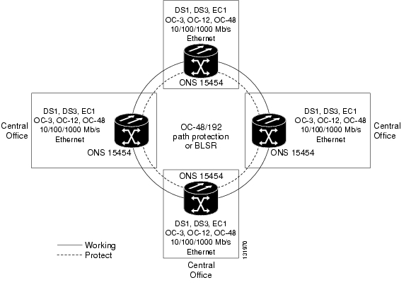
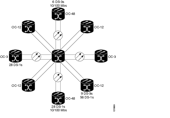
The ONS 15454 can be easily configured to carry TDM, ATM, data, and digital video services with path protection or BLSR protection. Its full range of interfaces provide incremental bandwidth increases as needed and supports DS-1, DS-3, DS-3 transmux, EC-1, OC-3, OC-12, OC-48, OC-192, 10/100 Mb/s, and Gigabit Ethernet line rates. The short reach (SR), intermediate reach (IR), and long reach (LR) optical interface cards along with the ability to support any network topology makes the ONS 15454 ideal for IOF transport applications. Figure 9-1 shows an example of an IOF transport in either a path protection or BLSR configuration.
Figure 9-1 Interoffice Transport
Typcial IOF Node Configurations
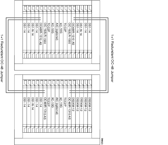
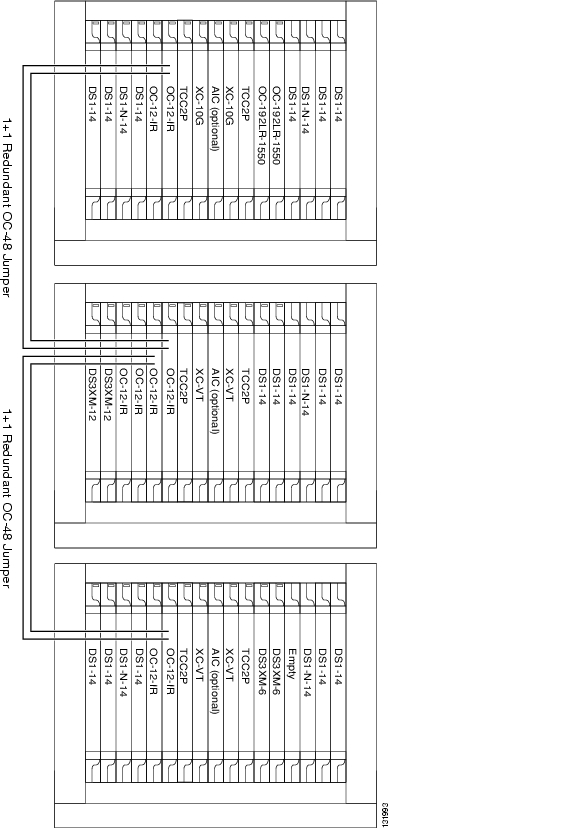
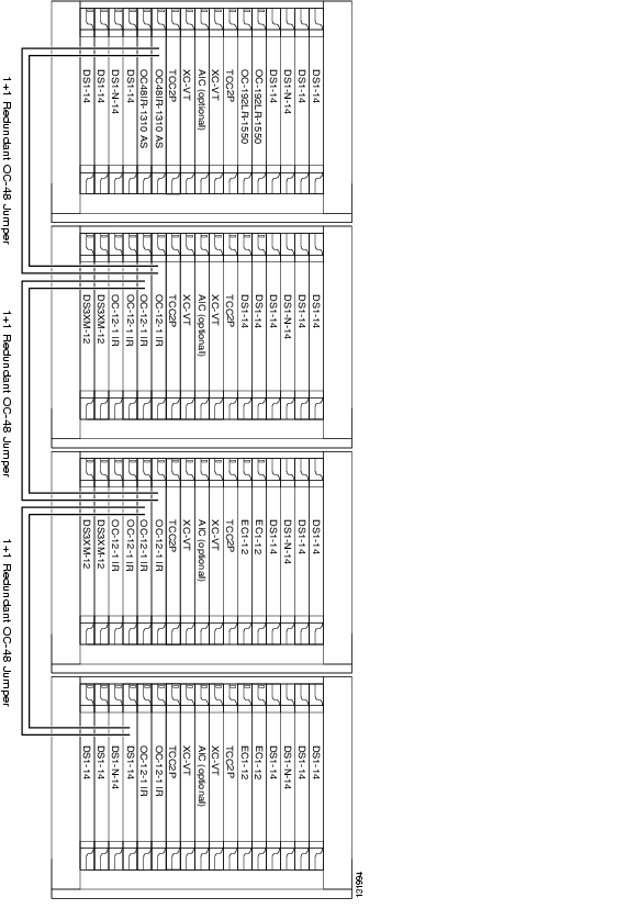
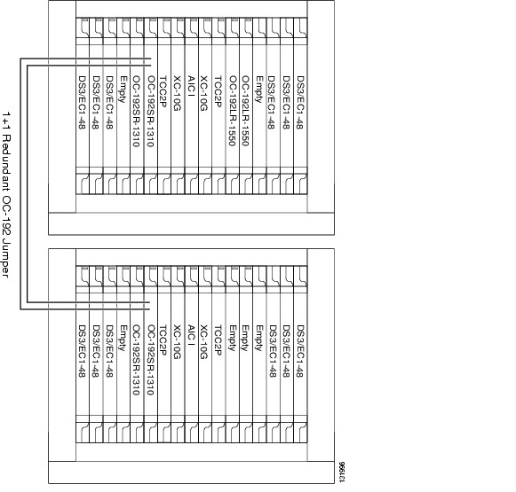
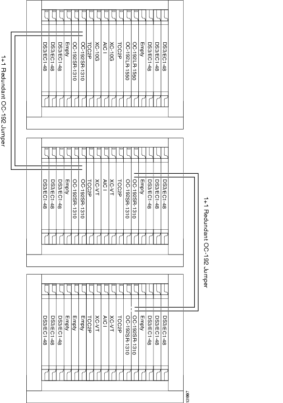
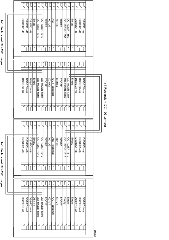
Figure 9-2, Figure 9-3, and Figure 9-4 show the shelf layouts for typical OC-192 IOF nodes. Note the empty card slots available to increase the capacity of the shelf.
Figure 9-2 OC-192 IOF Node Configured for 96 DS-3s Using High-Density Cards
Figure 9-3 OC-192 IOF Node Configured for 24 DS-3s and 24 EC-1s Using Low-Density Cards
Figure 9-4 OC-192 IOF Node Configured for 192 DS-3/EC-1s or 96 DS-3s and 96 EC-1s Using High-Density Cards
Metro Transport
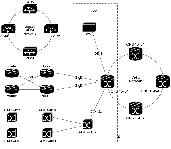
The ONS 15454 can groom services at the edge of the Metro transport network shown in Figure 9-5, packing the network with information and eliminating the need for multiple cross-connects and routers. Figure 9-6 shows the shelf layout of the ONS 15454 node located at the Interoffice Site.
Figure 9-5 Multi-Service Grooming at the Edge of the Metro Transport Network
Figure 9-6 Shelf Layout of a Multi-Service Grooming Node
Access Transport
The ONS 15454 provides the flexibility required to link remote sites to a serving central office (CO) and to aggregate a wide range of services at the edge of the network and transport them to the core of the network.
Open-Ended Path Protection Circuit
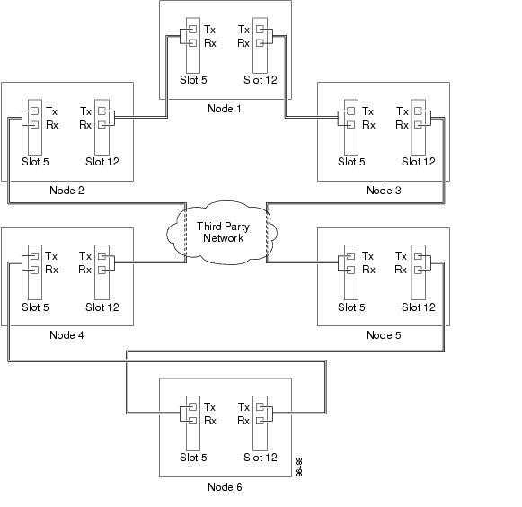
An open-ended path protection circuit allows you to route a circuit from one ONS 15454 network to another ONS 15454 network through a third party's network. Figure 9-7 shows an example of this topology. Node 1 is connected to ONS 15454 Nodes 2 and 3 through Slots 12 and 5. Trunk cards at Nodes 2 and 3 are connected to the third party's equipment.
Figure 9-7 Open-Ended Path Protection Example
The third party time slots must match the ONS 15454 card time slots to which they are connected. For example, if your trunk card is an OC-48, the third party's card must have STSs 1-48 available. You provision SONET DCC terminations for the ONS 15454 cards/ports that are connected to another ONS 15454. Do not create a DCC termination for the card/port that connects to the third-party's equipment. For example in Figure 9-10, DCC terminations are created at the following cards/ports:
•
•
•
To create an open-ended path protection circuit, you create three circuits. One circuit is created on the source ONS 15454 network. This circuit has one source and two destinations, one at each ONS 15454 that is connected to the third-party network. The second circuit is created on the third-party network so that the circuit travels across the network on two paths to the ONS 15454s. That circuit routes the two circuit signals across the network to ONS 15454 nodes that are connected to the network on other side. At the destination node network, the third circuit is created with two sources, one at each node connected to the third-party network. A selector at the destination node chooses between the two signals that arrive at the node, similar to a regular path protection circuit.
BLSR DRI
Note
DRI protection circuits act as protection channel access (PCA) circuits. In CTC, you set up DRI protection circuits by selecting the PCA option when setting up primary and secondary nodes during DRI circuit creation.
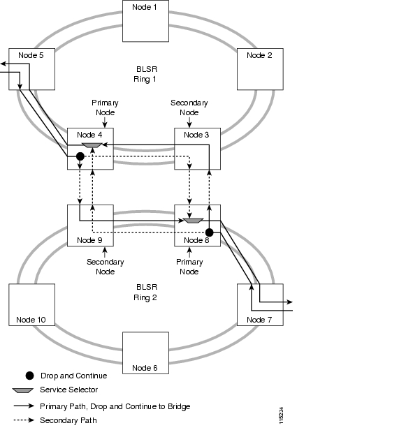
Figure 9-8 shows ONS 15454 nodes in a traditional BLSR-DRI topology with same-side routing. In Ring 1, Nodes 3 and 4 are the interconnect nodes, and in Ring 2, Nodes 8 and 9 are the interconnect nodes. Duplicate signals are sent between Node 4 (Ring 1) and Node 9 (Ring 2), and between Node 3 (Ring 1) and Node 8 (Ring 2). The primary nodes (Nodes 4 and 9) are on the same side, and the secondary nodes (Nodes 3 and 8) provide an alternative route. In Ring 1, traffic at Node 4 is dropped (to Node 9) and continued (to Node 10). Similarly, at Node 9, traffic is dropped (to Node 4) and continued (to Node 5).
Figure 9-8 Traditional BLSR DRI (Same Side Routing)
Figure 9-9 shows ONS 15454 nodes in a traditional BLSR-DRI topology with opposite-side routing. In Ring 1, Nodes 3 and 4 are the interconnect nodes, and in Ring 2, Nodes 8 and 9 are the interconnect nodes. Duplicate signals are sent from Node 4 (Ring 1) to Node 8 (Ring 2), and between Node 3 (Ring 1) and Node 9 (Ring 2). In Ring 1, traffic at Node 4 is dropped (to Node 9) and continued (to Node 8). Similarly, at Node 8, traffic is dropped (to Node 3) and continued (to Node 4).
Figure 9-9 ONS 15454 Traditional BLSR DRI (Opposite-Side Routing)
Figure 9-10 shows ONS 15454 nodes in an integrated BLSR-DRI topology. The same drop-and-continue traffic routing occurs at two nodes, rather than four. This is achieved by installing an additional OC-N trunk at the two interconnect nodes. Nodes 3 and 8 are the interconnect nodes.
Figure 9-10 ONS 15454 Integrated BLSR DRI
Path Protection DRI
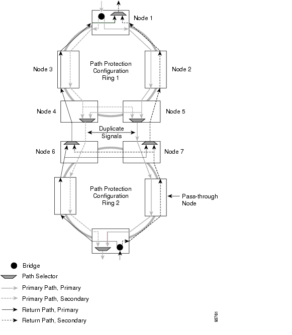
Figure 9-11 shows ONS 15454 nodes in a traditional drop-and-continue path protection DRI topology. In Ring 1, Nodes 4 and 5 are the interconnect nodes, and in Ring 2, Nodes 6 and 7 are the interconnect nodes. Duplicate signals are sent between Node 4 (Ring 1) and Node 6 (Ring 2), and between Node 5 (Ring 1) and Node 7 (Ring 2). In Ring 1, traffic at Node 4 is dropped (to Node 6) and continued (to Node 5). Similarly, at Node 5, traffic is dropped (to Node 7) and continued (to Node 4).
Figure 9-11 ONS 15454 Traditional Path Protection DRI
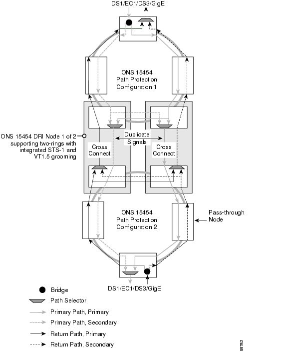
Figure 9-12 shows ONS 15454s in an integrated DRI topology. The same drop-and-continue traffic routing occurs at two nodes, rather than four. This is achieved by installing an additional OC-N trunk at the two interconnect nodes.
Figure 9-12 ONS 15454 Integrated Path Protection DRI
Path Protection/BLSR DRI Handoff Configurations
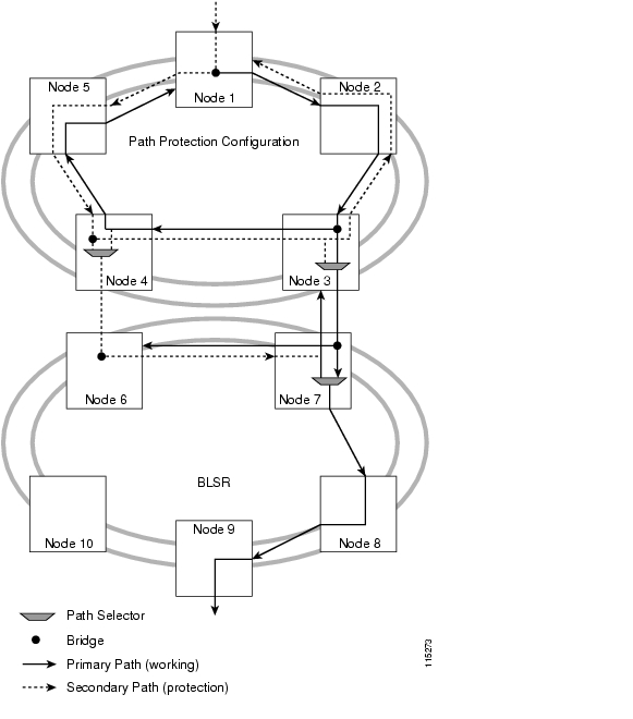
Path protection configurations and BLSRs can also be interconnected. In BLSR/path protection DRI handoff configurations, primary and secondary nodes can be the circuit source or destination, which is useful when non-DCC optical interconnecting links are present. Figure 9-13 shows an example of a path protection to BLSR traditional DRI handoff.
Figure 9-13 ONS 15454 Path Protection to BLSR Traditional DRI Handoff
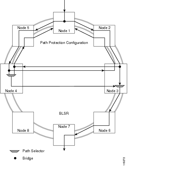
Figure 9-14 shows an example of a path protection to BLSR integrated DRI handoff.
Figure 9-14 ONS 15454 Path Protection to BLSR Integrated DRI Handoff
Linear ADM Configurations
You can configure ONS 15454s as a line of add/drop multiplexers (ADMs) by configuring one set of OC-N cards as the working path and a second set as the protect path. Unlike rings, linear (point-to-point) ADMs require that the OC-N cards at each node be in 1+1 protection to ensure that a break to the working line is automatically routed to the protect line.
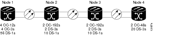
A common linear application is a configuration with a backbone route requiring traffic to be dropped and inserted at each site. Figure 9-15 shows an OC-192 linear application with 10 DS-1s and 2 DS-3s dropped at nodes 2 and 3. Four OC-192 modules are required at these nodes to handle traffic in both directions.
Figure 9-15 OC-192 Linear ADM 1+1 Protected
Figure 9-16 shows the shelf layouts for Nodes 1 to 4 in the above example.
Figure 9-16 OC-192 Linear ADM 1+1 Protected Shelf Layouts
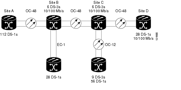
The ONS 15454 also supports distributed linear networks. Figure 9-17 shows a distributed OC-48 backbone with OC-12 and EC-1 uplinks. Site A collects DS-1 traffic from the remote sites, while, Sites B, C, and D are configured in an Ethernet Virtual Private Network (VPN). Note that at Site C, an OC-12 can be dropped from the same shelf that contains an OC-48 (see Figure 9-18).
Figure 9-17 Distributed Linear Network
Figure 9-18 Multi-homed Linear ADM Shelf Layout
Terminal Mode
In a Terminal Mode (TM) configuration, the ONS 15454 node terminates the entire SONET payload at each end of the fiber span. TM systems are generally employed in a basic transport application calling for a single system/single route solution.
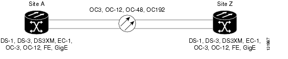
The ONS 15454 is designed to meet a wide range of capacity demands and can support TM configurations using OC-3, OC-12, OC-48 and OC-192 line rates. The ONS 15454 also supports an extensive range of mixed voice and data interfaces within the same shelf that hosts the SONET spans, making it extremely cost-effective for TM point-to-point applications shown in Figure 9-19.
Figure 9-19 Distributed Linear Network
Depending on the ONS 15454 port card used for the SONET span, protection spans can be added by installing another port card, such as OC-192, or by using additional ports on a multi-port card, such as OC-3 or OC-12. Table 9-1 lists the available TM protection schemes for electrical and optical interface cards.
Table 9-1 Terminal Mode Protection Schemes
Unprotected
X
X
1:1
X
1:N
X
1+1
X
Path protection
X
BLSR
X
PPMN
X
Traffic Aggregation
As an aggregator, the ONS 15454 combines the traffic from several low-speed sources for transmission across a high-speed link to another ONS 15454 node as illustrated in Figure 9-20.
Figure 9-20 Traffic Aggregation Application
Optical Hub
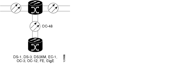
The multi-service flexibility and shelf capacity of the ONS 15454 enables a single shelf to act as an optical hub. As an optical hub, a single ONS 15454 can support multiple linear or ring systems. Traffic can be groomed an routed through an optical hub. Figure 9-21 shows an optical hub supporting two OC-48, four OC-12, and three OC-3 terminations.
Figure 9-21 Optical Hub Application
Figure 9-22 shows the shelf layout for the optical hub node in Figure 9-21.
Figure 9-22 Optical Hub Shelf Layout
Digital Cross-Connect Applications
The ONS 15454 digital cross-connect system (DCS) capabilities provide full STS and VT1.5 matrices to facilitate traffic grooming and consolidation. This allows the ONS 15454 to act as a 3/1 and/or 3/3 DCS. The DCS functionality is key to traffic grooming where you take a series of partially filled STSs and consolidate them into a few tightly packed STSs.
3/1 DCS
The VT Cross-connect (XCVT) and DS3XM (transmux) cards enable 3/1 DCS functionality. DS-1s, DS-3s and VT1.5 signals are mapped into STS circuits. The ONS 15454 can take several partially filled DS-3s and combine them into one DS-3. This ensures that the SONET ring is full of used channels, not idle channels.
The ONS 15454 also performs Time Slot Interchange (TSI) and in addition to cross-connecting. This allows signals to be groomed at the edge of the network, which can reduce or eliminate the need for expensive DCSs and fan out ports to the DCSs at a central office.
Figure 9-23, Figure 9-24, Figure 9-25, and Figure 9-26 show rack and shelf layouts for 3/1 DCS applications:
Figure 9-23 Single Shelf 3/1 DCS 112 DS1 Ports and 6 DS3 Transmux Ports
Figure 9-24 Two Shelf 3/1 DCS with 140 DS1 Ports and 18 DS3 Transmux Ports
Figure 9-25 Three-shelf 3/1 DCS with 224 DS1 ports, 18 DS3 Transmux ports, and 12 STS1 ports
Figure 9-26 Four Shelf 3/1 DCS with 280 DS1 ports, 24 DS3 Transmux Ports, and 24 STS1 Ports
3/3 DCS
The ONS 15454 also has an integrated 3/3 cross-connect, which is ideal for grooming DS-3s and STSs prior to passing them into a core network. A typical 3/3 DCS application for the ONS 15454 is at IOF sites where local loops converge.
Table 9-2 lists the 3/3 DCS configurations supported by the ONS 15454.
Note
Figure 9-27, Figure 9-28, Figure 9-29, and Figure 9-30 show the rack and shelf layouts for the 3/3 DCS applications:
Figure 9-27 3/3 DCS Application with 192 DS-3/STS-1 Ports
Figure 9-28 3/3 DCS Application with 264 DS-3 Ports
Figure 9-29 3/3 DCS Application with 336 DS-3 Ports
Figure 9-30 3/3 DCS Application with 768 DS-3/STS-1 Ports
Regenerator Site
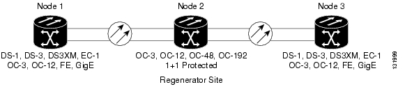
The ONS 15454 can be configured as an effective regenerator. An added benefit of this configuration is that when new services are needed at the regenerator, you simply add an interface card to the ONS 15454 to support the services. This does not require any new software or network engineering, just plug in the interface card and turn up the service. Figure 9-31 shows the ONS 15454 supporting a regenerator configuration for a linear ADM network. The ONS 15454 can also act as a regenerator for other SONET topologies including path protection, BLSR, and virtual rings, and PPMN meshes. Adding new interface cards and activating new services is non-service affecting.
Figure 9-31 Regenerator Application for a Linear Network
Regenerators are popular for long-haul systems where signal regeneration and future access to traffic is required. Another popular configuration is the extension of digitized video traffic to other sites to eliminate the costs of building a new headend site. However, the most exciting application is the pre-positioning of SONET terminals as future service nodes. The continuing reduction in SONET costs has made this a feasible deployment option. The ONS 15454 supports this application since an ONS 15454 can be configured to support terminal mode, ADM, ring, hub, and regenerator applications. Figure 9-32 shows the shelf layout for the ONS 15454 OC-48 regenerator node shown in Figure 9-31.
Figure 9-32 OC-48 Regenerator Node Shelf Layout
Passive DWDM Applications
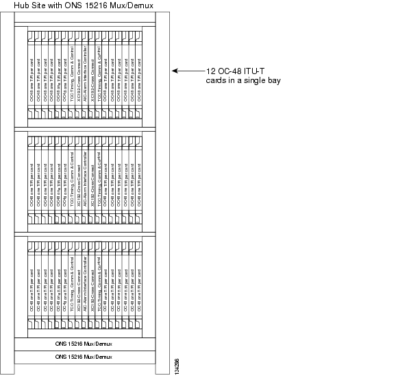
The ONS 15454 supports 18 different OC48 ELR ITU-T 200 GHz, 37 OC48 ELR ITU-T 100 GHz cards, or OC192 LR ITU-T 1000Hz to provide you with up to 320 Gb/s of bandwidth over a single fiber. Deployed where fiber routes are constrained, this fiber bandwidth leverages the installed fiber resources and reduces the need to install new fiber. Matching the ONS 15454 ITU-T cards with the ONS 15216 passive DWDM filters greatly expands the capabilities of the ONS 15454. Figure 9-33 shows a typical 7ft. x 19in. rack layout for a DWDM hub site using ONS 15454 OC48 ELR ITU-T cards and multiplexers and demultiplexers.
Figure 9-33 DWDM Hub Site Layout
Figure 9-34 is an example of an optical add/drop multiplexer (OADM) site where multiple channels can be dropped an inserted. The 7ft. x 19in. rack is equipped with a single ONS 15454 shelf containing the ONS 15454 OC48 ELR ITU-T optics cards, OADM unit, and EDFA.
Figure 9-34 OADM Site Shelf Layout
Wavelength Multiplexer
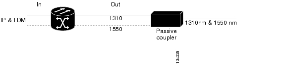
The multi-wavelength capabilities of the ONS 15454 allow it to easily interface with passive WDM filters.
Since the WDM/DWDM systems are transparent to the ONS 15454, all of the topologies described in this document can be run over WDM/DWDM networks. This includes linear networks, rings, data meshes, PPMN and Virtual rings.
1310 nm and 1550 nm OC-48 and OC-12 cards can be passed through inexpensive passive couplers to be multiplexed over a single fiber. See Figure 9-35.
Figure 9-35 Passive DWDM Interface
Figure 9-36 shows the shelf layout for an ONS 15454 Passive Wavelength Multiplexing node.
Figure 9-36 Passive Wavelength Multiplexing Node
MSTP DWDM Applications
Cisco ONS 15454 MSTP nodes can be provisioned for metro access and metro core DWDM network applications. Metro access networks are 60 km or less in size. Channels are not equalized and dispersion compensation is not applied. Metro access networks have few spans and very low span loss, so the signal link budget is the limiting factor for performance. Metro core networks can be up to 400 km in size. The channel power is equalized and dispersion compensation is applied. Metro core networks often include multiple spans and amplifiers, so the optical signal-to-noise ratio (OSNR) is the limiting factor for channel performance in metro core networks.
Within DWDM networks, the ONS 15454 uses a communications protocol, called node services protocol (NSP), to communicate with other nodes. NSP automatically updates nodes whenever a change in the network occurs. Each ONS 15454 DWDM node can:
•
•
•
For ONS 15454 MSTP DWDM node configurations, refer to Chapter 4 in this document.
Ethernet Applications
The Cisco ONS 15454 integrates Ethernet into a SONET time-division multiplexing (TDM) platform. The ONS 15454 supports CE-. E-, G-, and ML-Series Ethernet cards.
The CE-Series card is the CE-100T-8, which is a Layer 1 mapper card with eight 10/100 Ethernet ports. It maps each port to a unique SONET circuit in a point-to-point configuration. The CE-100T-8 card allows you to provision and manage an Ethernet private line service like a traditional SONET line. CE-100T-8 card applications include providing carrier-grade Ethernet private line services and high-availability 10/100 Mb/s data transport.
The CE-100T-8 has eight POS ports, numbered one through eight. Each POS port is statically mapped to a matching Ethernet port. Each POS port terminates an independent contiguous SONET concatenation (CCAT) or virtual SONET concatenation (VCAT). The CE-100T-8 supports circuit sizes from VT1.5-nV (n= 1 to 64) to STS-3c.
The ONS 15454 E-Series cards include the E100T-12, E100T-G, E1000-2, and E1000-2-G. An ONS 15454 supports a maximum of ten E-Series cards, however Cisco recommends that you place no more than four 12-port Ethernet cards in a single shelf. You can insert these cards in slots 1 - 6 and 12 - 17. Use the E-Series cards if your application requires Layer 2 switching. These cards support point-to-point, hub and spoke, and shared packet ring topologies with a maximum circuit size of STS-12c.
The G-Series cards include the G1000-4 and G1K-4. These cards map up to four Gigabit Ethernet interfaces onto a SONET transport network. G-Series cards provide scalable and provisionable transport bandwidth at signal levels up to STS-48c per card. The G-Series cards provide line rate forwarding for all Ethernet frames (unicast, multicast, and broadcast) and can be configured to support Jumbo frames (defined as a maximum of 10,000 bytes). Use the G-Series cards if your application is for an Ethernet private line service providing transparent LAN services (TLS), line rate GigE, and high-availability transport for applications such as storage over MAN/WANs. You can independently map the four ports on the G-Series card to any combination of STS-1, STS-3c, STS-6c, STS-9c, STS-12c, STS-24c, and STS-48c circuit sizes, provided the sum of the circuit sizes that terminate on a card do not exceed STS-48c.
The ML-Series cards consist of the ML100T-12 and ML-1000-2. These cards integrate high-performance Ethernet transport, switching, and routing into a single card. Use the ML-Series cards if your application calls for Layer 2 bridging and/or Layer 3 routing, switching, or forwarding of data packets. ML-Series cards can be installed in any of the multipurpose slots. For a description of ML-Series software features and configuration files, see the Cisco ONS 15454 Ethernet Card Software Feature and Configuration Guide.
The ONS 15454 is designed to be located at the edge and core of the network to provide Ethernet transport between Enterprise locations, data centers, remote sites, and Internet service providers (ISPs). Use Table 9-3 to select the Ethernet card and features for your application. For more information about Cisco ONS 15454 Ethernet cards and software configurations, refer to the Cisco Ethernet Card Software Feature and Configuration Guide.
Table 9-3 Supported Ethernet Features
CE-100T-8
8
—
15454-SA-ANSI
15454-SA-HD
> R5.0.2
Transparent
Transparent
Transparent
Yes
E100T-12
12
—
All
> R2.0
509
Configurable
Linear Mode
—
E100T-12G
12
—
All
> R2.0
509
Configurable
Linear Mode
—
E1000-2
—
2
All
> R2.0
509
Configurable
Linear Mode
—
E1000-2-G
—
2
All
> R2.0
509
Configurable
Linear Mode
—
G1000-4
—
4
15454-SA-ANSI
15454-SA-HD
> R3.2
Transparent
Transparent
Transparent
—
G1K-4
—
4
15454-SA-ANSI
15454-SA-HD
> R3.2
Transparent
Transparent
Transparent
—
ML100T-12
12
—
15454-SA-ANSI
15454-SA-HD
> R4.0
255 Logical VLANs, 900 VLAN Subinterfaces
Configurable
Yes
Yes
ML1000-2
—
2
15454-SA-ANSI
15454-SA-HD
> R4.0
255 Logical VLANs, 900 VLAN Subinterfaces
Configurable
Yes
Yes1
CE-100T-8
HO, LO
Yes
1548 bytes
Point-to-Point1
Transparent
—
VT1.5-nV (n= 1 to 64) to STS-1-2v
STS-3C (100 Mb/s)
E100T-12
—
—
1522 bytes
Limited to 9-12 kb/s
Yes, 8 instances
—
STS-1 to STS-12C
STS-12C
E100T-12G
—
—
1522 bytes
Limited to 9-12 kb/s
Yes, 8 instances
—
STS-1 to STS-12C
STS-12C
E1000-2
—
—
1522 bytes
Limited to 9-12 kb/s
Yes, 8 instances
—
STS-1 to STS-12C
STS-12C
E1000-2-G
—
—
1522 bytes
Limited to 9-12 kb/s
Yes, 8 instances
—
STS-1 to STS-12C
STS-12C
G1000-4
—
—
10,000 bytes
Point-to-Point 1
Transparent
—
STS-1 to STS-24C
STS-48C
G1K-4
—
—
10,000 bytes
Point-to-Point 1
Transparent
—
STS-1 to STS-24C
STS-48C
ML100T-12
HO2
SW-LCAS3
10,000 bytes
Yes4
Yes, 255 STP and RSTP instances
Yes
1 Mb/s increments at port level
STS-24C
ML1000-2
HO 2
SW-LCAS 3
10,000 bytes
Yes 4
Yes, 255 STP and RSTP instances
Yes
1 Mb/s increments at port level
STS-24C
1 Multicast support limited to port-to-port circuits.
2 Requires Software Release 5.0 or higher.
3 Ciso's proprietary software link capacity adjustment scheme (SW-LCAS) is the software implementation of a LCAS-type feature. SW-LCAS differs from LCAS because it is not errorless and uses a different handshaking mechanism.
4 No IGMP snooping, which allows multicast to be treated as broadcast.
Ethernet Private Line
The CE- and G-Series cards allow you to provision and manage an Ethernet private line service like a traditional SONET line. Ethernet private lines provide carrier-grade transparent LAN services (TLS) between two ONS 15454 nodes. No VLAN knowledge or layer 2 provisioning is required in this application. Only simple provisioning of STS cross-connects is required.
The Ethernet frame from the data network is transmitted on the Ethernet cable into the standard RJ-45 port on a CE-100T-8 card. The CE-100T-8 card transparently maps Ethernet frames into the SONET payload using packet-over-SONET (POS) encapsulation. The POS circuit with its encapsulated Ethernet inside is then multiplexed onto an OC-N card like any other SONET STS.
The G1000-4 and G1K4 cards map a single Ethernet port to a single STS circuit. You can independently map the four ports on a G-Series card to any combination of STS-1, STS-3c, STS-6c, STS-9c, STS-12c, STS-24c, and STS-48c circuit sizes, provided that the sum of the circuit sizes that terminate on a card do not exceed STS-48c.
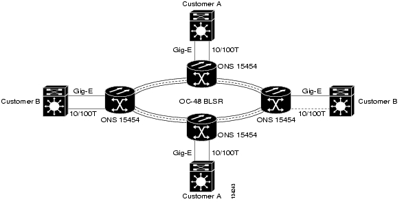
Standard SONET path protection configurations/BLSRs provide less than 50 milliseconds restoration of service for Ethernet private line transport. Figure 9-37 illustrates an example of an Ethernet Private Line application. In this example, data traffic from the Fast Ethernet port of a switch travels across the
point-to-point circuit to the Fast Ethernet port of another switch.
Figure 9-37 Ethernet Private Line
Transparent LAN Service
A transparent LAN service (TLS) is a Virtual Ethernet Connection (VEC) that appears to act as an Ethernet wire, where all Ethernet traffic is seen by all remote ends. The customer only sees its end devices and the traffic generated or going through these equipments. In other words, the Metro network devices do not send any Protocol Data Units (PDUs) to the customer network. The Layer 2 protocols such as STP, CDP, VTP and EtherChannel must be transported transparently across the TLS as they would be over "dark fiber". The Metro network appears as an Ethernet segment to the customer. In addition, this service must allow any number of customer VLANs to be tunneled together the Metro network run, so that the customer is not limited by number nor forced by the service provider to use specific assigned VLANs. This service is a multi-point to multi-point connection type of service illustrated in Figure 9-38.
Figure 9-38 Transparent LAN Service Architecture
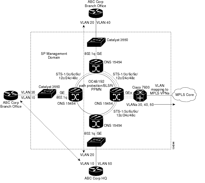
As illustrated on the Figure 9-39, several types of services can be delivered through the same client network interface with this architecture. The TLS between the corporate office and the branch offices (VLAN 10 and 20) and Access to MPLS VPNs are delivered over the same UNI and GE circuits. The Ethernet Virtual Circuit Service is locally switched and is indicated logically by the dashed arrows (VLANs 10, 20). Access to the corporate network is provided via mapping VLANs (30, 40, and 50) to MPLS VPNs in the SONET network. Both of these services can operate at the same time over the same UNI. Only three STSs or Virtual Circuits (VCs) are needed to provision these two services.
Figure 9-39 Transparent LAN Service Example
Metro Ethernet Solution
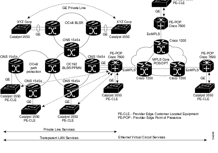
A complete Metro Ethernet solution illustrating TLS and GE private line services or Ethernet Virtual Circuit services is shown in Figure 9-40. The G-Series cards support frame forwarding for unicast, multicast, and broadcast traffic, so Multicast traffic can be transported transparently by this TLS Metro Ethernet solution over the optical Metro network.
Figure 9-40 Metro Ethernet Solution
Resilient Packet Ring
Resilient Packet Ring (RPR) is an emerging network architecture designed for metro fiber ring networks. This new MAC protocol is designed to overcome the limitations of IEEE 802.1D Spanning Tree Protocol (STP), IEEE 802.1W Rapid Spanning Tree Protocol (RSTP), and SONET in packet-based networks. RPR operates at the Layer 2 level and is compatible with Ethernet and SONET.
The ML-Series card's RPR relies on the quality of service (QoS) features of the ML-Series card for efficient bandwidth utilization with service level agreement (SLA) support. ML-Series card QoS mechanisms apply to all SONET traffic on the ML-Series card, whether passed-through, bridged, or stripped.
When a ML-Series card is configured with RPR and made part of a shared packet ring (SPR), the ML-Series card assumes it is part of a ring. If a packet is not destined for devices attached to the specific ML-Series, the ML-Series card simply continues to forward this transit traffic along the SONET circuit, relying on the circular path of the ring architecture to guarantee that the packet will eventually arrive at the destination. This eliminates the need to queue and forward the packet flowing through the nondestination ML-Series card. From a Layer 2 or Layer 3 perspective, the entire RPR looks like one shared network segment.
RPR supports operation over protected and unprotected SONET circuits. On unprotected SONET circuits, RPR provides SONET-like protection without the redundant SONET protection path. Eliminating the need for a redundant SONET path frees bandwidth for additional traffic. RPR also incorporates spatial reuse of bandwidth through a hash algorithm for east/west packet transmission. RPR utilizes the entire ring bandwidth and does not need to block ring segments like STP or RSTP.
Because STP or RSTP is not in effect between nodes when RPR is configured, the transmitting RPR port strips its own packets after they return from circling the ring. A hash algorithm is used to determine the direction of the packet around the RPR. Figure 9-41 illustrates how RPR handles this operation.
Figure 9-41 RPR Packet Handling Operations
Configuring ML-Series Cards for RPR
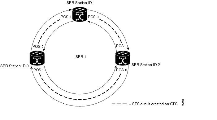
RPR on the Cisco ONS 15454 enables two or more ML-Series cards to become one functional network segment or SPR. The bridged ML-Series cards are connected to each other through point-to-point STS circuits, which use one of the first ML-Series card's POS ports as a source and one of the second ML-Series card's POS ports as a destination. All ML-Series cards in an SPR must be connected directly or indirectly by point-to-point circuits.
The point-to-point circuits use the ONS 15454 SONET network for transport and protection. Provision the point-to-point circuits using Cisco Transport Controller (CTC) or TL1 in the same manner as an ONS 15454 OC-N card STS circuits. The Cisco ONS 15454 Procedure Guide or the Cisco ONS 15454 Procedure Guide provides specific instructions about how to create an automatically routed optical circuit.
When configuring a point-to-point circuit on the ML-Series perform the following:
•
•
•
After the CTC circuit process is complete, begin a Cisco IOS session to configure RPR/SPR on the ML-Series card and interfaces.
Note
Configuring Cisco IOS on the ML-Series Cards for RPR/SPR
You configure RPR on the ML-Series cards by creating an SPR interface from the Cisco IOS CLI. The SPR is a virtual interface, similar to an EtherChannel interface. The POS interfaces are the physical interfaces associated with the RPR SPR interface. An ML-Series card supports a single SPR interface. The SPR interface has a single MAC address and provides all the normal attributes of a Cisco IOS interface, such as support for default routes. An SPR interface is considered a trunk port, and like all trunk ports, subinterfaces must be configured for the SPR interface to become part of a bridge group.
An SPR interface is configured similarly to a EtherChannel (port-channel) interface. The members of the SPR interface must be POS interfaces. Instead of using the channel-group command to define the members, you use the spr-intf-id command. And like port-channel, you configure the SPR interfaces instead of the POS interface.
Caution
Caution
To provision RPR and to assign a POS interface on the ML-Series to the SPR, follow the procedures listed in the Cisco Ethernet Card Software Feature and Configuration Guide. Figure 9-42 shows an example of an RPR IOS configuration.
Figure 9-42 RPR Cisco IOS Configuration
Ethernet over MPLS
Ethernet over MPLS (EoMPLS) provides a tunneling mechanism for Ethernet traffic through an MPLS-enabled Layer 3 core. It encapsulates Ethernet protocol data units (PDUs) inside MPLS packets and using label stacking forwards them across the MPLS network. EoMPLS is an Internet Engineering Task Force (IETF) standard-track protocol based on the Martini draft, specifically the draft-martini-l2circuit-encap-mpls-01 and draft-martini-l2circuit-transport-mpls-05 sections.
EoMPLS allows you to offer customers a virtual Ethernet line service or VLAN service using the service provider's existing MPLS backbone. It also simplifies service provider provisioning, since the provider edge customer-leading edge (PE-CLE) equipment only needs to provide Layer 2 connectivity to the connected customer edge (CE) equipment.
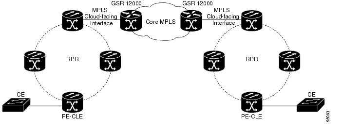
Figure 9-43 shows an example of EoMPLS implemented on a service provider network. In the example, the ML-Series card acts as PE-CLE equipment connecting to the Cisco GSR 12000 Series through an RPR access ring. Point-to-point service is provided to CE equipment in different sites that connect through ML-Series cards to the ML-Series card RPR access ring.
Figure 9-43 EoMPLS Service Provider Network
Implementing EoMPLS on a network requires ML-Series card interfaces to play three major roles. The ML-Series card interface roles must be configured on both sides of the EoMPLS point-to-point service crossing the MPLS core as follows:
•
•
•
Implementing EoMPLS across a network requires setting up directed Label Distribution Protocol (LDP) sessions (LSPs) between the ingress and egress PE-CLE routers to exchange information for a virtual circuit (VC). Each VC consists of two LSPs, one in each direction, since an LSP is a directed path to carry Layer 2 frames in one direction only.
EoMPLS uses a two-level label stack to transport Layer 2 frames, where the bottom/inner label is the VC label and the top/outer label is the tunnel label. The VC label is provided to the ingress PE-CLE by the egress PE-CLE of a particular LSP to direct traffic to a particular egress interface on the egress PE-CLE. A VC label is assigned by the egress PE-CLE during the VC setup and represents the binding between the egress interface and a unique and configurative VC ID. During a VC setup, the ingress and egress PE-CLE exchange VC label bindings for the specified VC ID.
An EoMPLS VC on the ML-Series card can transport an Ethernet port or an IEEE 802.1Q VLAN over MPLS. A VC type 5 tunnels an Ethernet port and a VC type 4 transports a VLAN over MPLS. In a VC type 5 session, the user can expect any traffic that is received on an ML-Series card PE-CLE port with an mpls Layer 2 transport route command to be tunneled to the remote egress interface on the far-end ML-Series card PE-CLE port. With a VC type 4, a user can expect the tunnel to act as physical extension to that VLAN. The EoMPLS session commands are entered on a VLAN subinterface on the PE-CLE, and only VLAN-tagged traffic received on that port will be tunneled to the remote PE-CLE.
EoMPLS on the ML-Series card has the following characteristics:
•
•
•
•
•
•
•
•
EoMPLS on the ML-Series card has the following restrictions:
•
•
•
•
•
•
Caution
Configuring EoMPLS
The ML-Series peer cards on both endpoints of the EoMPLS point-to-point service must be configured. Perform the following configuration tasks to enable EoMPLS:
•
•
•
•
•
These are the guidelines for configuring EoMPLS:
•
•
•
•
•
Figure 9-44 illustrates the sample network that the configuration commands reference.
Figure 9-44 EoMPLS Configuration Example
Cable Modem Aggregation
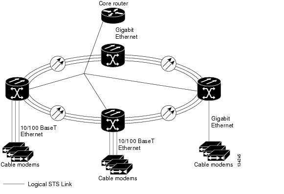
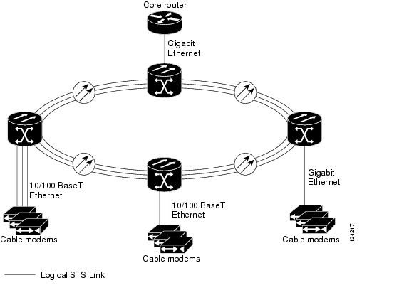
The ONS 15454 is ideal for providing Ethernet aggregation at remote sites and them back to one central site or headend location. Aggregation can be performed via point-to-point Transparent LAN Service (TLS) shown in Figure 9-45 or over a Shared Packet Ring shown in Figure 9-46.
Figure 9-45 Point-to-Point Cable Modem Aggregation
Figure 9-46 Shared Packet Ring Cable Modem Aggregation
Wireless Networking
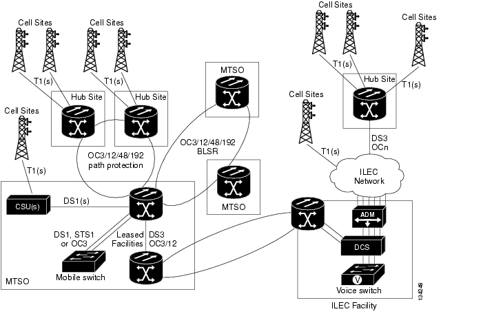
The ONS 15454 provides cost-effective transport of services between mobile telephone switch offices (MTSOs) and hub sites. In Figure 9-47, the ONS 15454 provides T1 links from the cell sites to the hub sites and SONET transport between the MTSO sites and ILEC transport facilities. It also provides the optical bandwidth management between each MTSO site.
Figure 9-47 Wireless Networking Optical Bandwidth Management
Video Transport
The ONS 15454 provides the flexibility required to support the next generation hybrid fiber coax (HFC) and IP video networks.
HFC Networks
Next generation HFC networks are based on the regional hub concept and includes the following attributes:
•
•
•
•
•
•
Centralization of capital-intensive investments at the regional hub allows the cable operators to spread the investments across a wider base and provides a platform for offering a common set of services to subscribers and other cable operators.
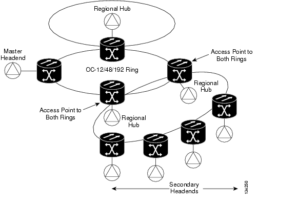
In Figure 9-48, the ONS 15454 MSPP is used to transport voice over IP (VoIP), high-speed data access, and video signals from the Master Headend to all Regional Headends and Fiber Hubs using SONET point-to-point and drop and continue circuits.
Figure 9-48 Next Generation HFC Network Architecture
Redundant systems can be installed to avoid single points of failure, as shown in Figure 9-49.
Figure 9-49 Avoiding Single Points of Failure
MSOs have been trading systems to create contiguous serving areas. These contiguous serving areas form a region. A region may have 10 to 20 different cable systems connected to a Regional Hub.
Contiguous serving areas allow MSOs to consolidate headends from various areas into a Master Headend. To consolidate headends, MSOs can transport their standard channel line up from the Master Headend to Secondary Headends. Localized broadcast services, advertising, and must-carry channels are added to the standard line up at the Secondary Headend.
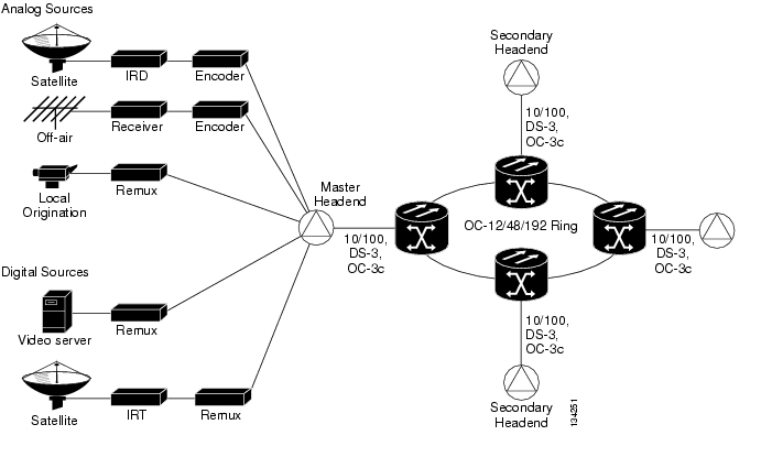
In Figure 9-50, the ONS 15454 transports the standard channel line up over a SONET path protection to each Secondary Headend through its drop and continue capability.
Figure 9-50 Headend Consolidation
Video Over IP
Cable MSOs have been deploying separate networks for delivering cable television services and IP-based services such as high-speed data and IP telephony. The Video over IP architecture enables video services to be distributed via the IP network, enabling network consolidation and functionality not possible with the traditional video transport solutions.
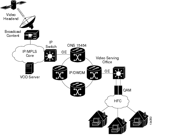
The Video over IP architecture leverages the current digital video systems being deployed today while exploiting the benefits of IP networks for distributing broadcast video and video-on-demand (VOD) from the video hendend offices (VHOs) and video serving offices (VSOs) to the HFC access network. The inherent routing capability of the Video over IP architecture provides flexibility in the placement of video sources and improves network efficiency by enabling any video source to deliver content to any set-top box (STB). A reference architecture for Video over IP is depicted in Figure 9-51.
Figure 9-51 Video Over IP Reference Architecture
Many MSOs have a single unidirectional optical link between the headend and distribution hubs. DWDM (as opposed to CWDM) is typically chosen as the optical multiplexing technology, because the distance between the headend and distribution hubs often exceeds the CWDM range.
Gigabit Ethernet VOD can use DWDM optical components that are cost reduced to include DWDM lasers on ONS 15454 nodes that are used for transport. For example, the ONS 15454 nodes shown in Figure 9-52 are configured with G-Series Ethernet cards provisioned in the Gigabit Ethernet tranponder mode for efficient delivery VOD channels.
Figure 9-52 Efficient Distribution of VOD Channels
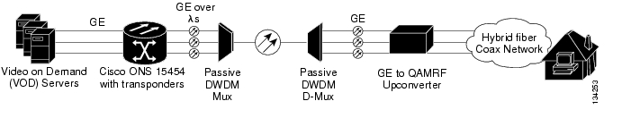
Figure 9-53 shows the basic wiring between the VOD server, G-Series Ethernet card, and the passive DWDM multiplexer.
Figure 9-53 Basic Gigabit Ethernet Transponder Wiring Diagram
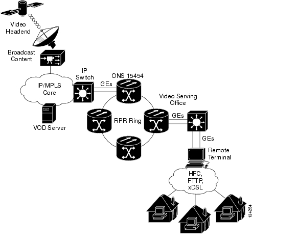
You can also use ONS 15454 separate GE channels on ML-Series cards configured for RPR to distribute multi-cast broadcast and uni-cast VOD traffic between the VHOs and SVOs as illustrated in Figure 9-54. The access facilities between the VSO and remote terminals can either be HFC, FTTP, or xDSL.
Figure 9-54 RPR Video Distribution Architecture
SAN Extension Options
Storage Area Networks (SANs) consolidate data storage needs, increase storage efficiency, and reduce capital and operational costs (CapEx and OpEx). SAN extension enables disaster recovery and business continuance applications by transporting SAN protocols over long distances and thereby interconnecting isolated storage islands.
The following options are available for extending SAN over metro or WAN distances:
•
•
•
•
SAN Extension services can be further classified as private line services and wire line services.
Private Line Services
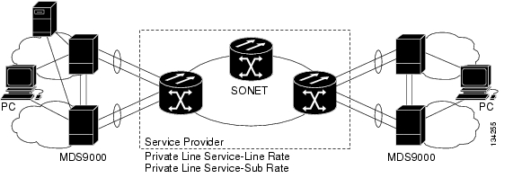
SONET-based storage services can extend the SAN extension solutions to distances over 2000 Km by using spoofing techniques and are not subject to the buffer credit limitations imposed by storage switches and directors. SONET sub-rate support and 50 msec recovery time is ideal for supporting SLA's for a large number of enterprise applications. Figure 9-55 shows a typical SONET-based network providing both line rate and sub-rate services.
Figure 9-55 SONET-Based Private Line Service
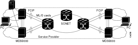
Wire Line Services (FCIP Over SONET)
Wire Line Services over SONET is another viable low-cost way to extend SAN traffic. FCIP can be implemented using Layer 3 components of the ML-Series card on the ONS 15454. ONS 15454 networks can offer the multiplexing capability of IP and the protection of SONET. The ONS 15454 is also ideal for both asynchronous and synchronous applications. A typical service architecture is shown in Figure 9-56.
Figure 9-56 FCIP Over SONET—Point to Point
![]()
![]()
![]()
![]()
![]()
![]()
![]()
![]()
Posted: Tue Nov 27 11:03:46 PST 2007
All contents are Copyright © 1992--2007 Cisco Systems, Inc. All rights reserved.
Important Notices and Privacy Statement.