|
|

Table Of Contents
Synchronous, Asynchronous, and Plesiochronous Signals
Reduced Back-to-Back Multiplexing
Convergence of Voice, Data, and Video
Reduced Cabling and Use of DSX Panels
Enhanced Performance Monitoring
Convergence of SONET and SDH Hierarchies
Asynchronous and Synchronous Tributaries
SONET Primer
This appendix provides an introduction to the Synchronous Optical NETwork (SONET) standard. For additional information on SONET, refer to:
•
ANSI T1.105 - 1995 American National Standard for Telecommunications, Synchronous Optical Network (SONET)
•
•
•
The following topics are covered in this chapter:
•
•
Background of SONET
Before SONET, the first generations of fiber optic systems in the public telephone network used proprietary architectures, equipment, line codes, multiplexing formats, and maintenance procedures. The users of this equipment included the Regional Bell Operating Companies (RBOCs) and Interexchange Carriers (IXCs) in the U.S., Canada, Korea, Taiwan, and Hong Kong. These operating companies wanted an industry standard so they could mix and match equipment from different suppliers. The task of creating such a standard was taken up in 1984 by the Exchange Carriers Standards Association (ECSA) to establish a standard for connecting one fiber system to another. This standard became known as SONET, which stands for Synchronous Optical NETwork.
SONET is an ANSI standard for synchronous data transmission on optical media. SONET defines optical carrier (OC) levels and electrically equivalent synchronous transport signals (STSs) for the fiber-optic based transmission hierarchy. It was formulated by the Exchange Carriers Standards Association (ECSA) for the American National Standards Institute (ANSI), which sets industry standards in the U.S. for telecommunications and other industries. Internationally, Synchronous Digital Hierarch (SDH) is the equivalent of SONET. Together, these standards ensure that world-wide digital telecommunications networks can interconnect.
SONET defines the following standards:
•
•
•
•
Synchronous, Asynchronous, and Plesiochronous Signals
To understand correctly the concepts and details of SONET, it's important to be clear about the meaning of Synchronous, Asynchronous, and Plesiochronous.
In a set of Synchronous signals, the digital transitions in the signals occur at exactly the same rate. There may, however, be a phase difference between the transitions of the two signals, and this would lie within specified limits. These phase differences may be due to propagation time delays or jitter introduced into the transmission network. In a synchronous network, all the clocks are traceable to one Primary Reference Clock (PRC). The accuracy of the PRC is better than ±1 in 1011 and is derived from a cesium atomic standard.
If two digital signals are Plesiochronous, their transitions occur at "almost" the same rate, with any variation being constrained within tight limits. For example, if two networks need to interwork, their clocks may be derived from two different PRCs. Although these clocks are extremely accurate, there is a difference between one clock and the other. This is known as a plesiochronous difference.
In the case of Asynchronous signals, the transitions of the signals do not necessarily occur at the same nominal rate. Asynchronous, in this case, means that the difference between two clocks is much greater than a plesiochronous difference. For example, if two clocks are derived from free-running quartz oscillators, they could be described as asynchronous.
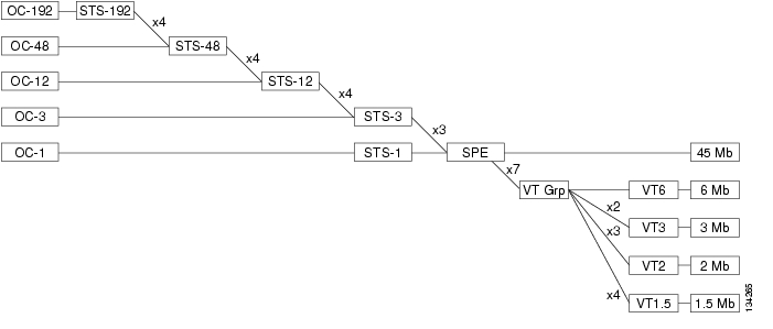
SONET Signal Hierarchy
SONET uses a basic transmission rate of Synchronous Transport Signal level-1 (STS-1), which is equivalent to 51.84 Mb/s. There are 8,000 STS-1 frames per second in a STS-1 signal. Higher-level signals are integer multiples of the base rate. For example, STS-3 is three times the rate of STS-1 (3 x 51.84 = 155.52 Mb/s). An STS-12 rate would be 12 x 51.84 = 622.08 Mb/s. Table B-1 shows the hierarchy of STS-1 signals.
SONET Frame Structure
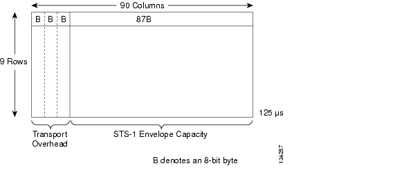
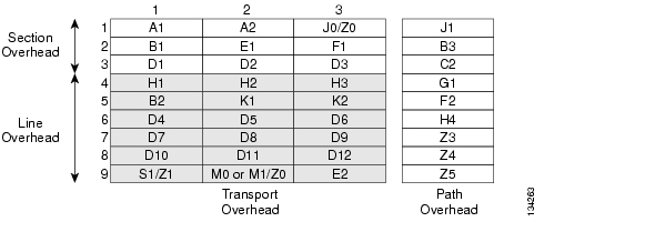
The frame format of the STS-1 signal is shown in Figure B-1. The STS-1 frame has a recurring rate of 8000 frames a second and a frame rate of 125 microseconds The STS-1 frame consists of 90 columns and 9 rows. In general, the frame can be divided into two main areas: Transport overhead and the STS-1 synchronous payload envelope (STS-1 SPE).
Figure B-1 STS-1 Frame Format
The first three columns in each of the nine rows carry the section and line overhead bytes. Collectively, these 27 bytes are referred to as Transport Overhead. Transport Overhead is composed of section overhead and line overhead. The STS-1 path overhead is part of the synchronous payload envelope. The STS-1 payload has the capacity to transport up to:
•
•
•
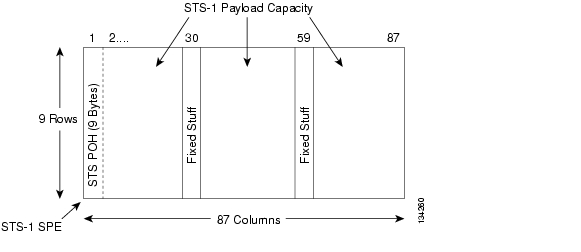
Columns 4 through 90 are reserved for payload signals (i.e., DS1 and DS3) and is referred to as the STS-1 SPE. The optical counterpart of the STS-1 is the optical carrier level 1 signal (OC-1), which is the result of a direct optical conversion after scrambling. The STS-1 SPE can be divided into two parts: STS path overhead and the payload, as shown in Figure B-2. The payload is the revenue-producing traffic being transported and routed over the SONET network. Once the payload is multiplexed into the synchronous payload envelope, it can be transported and switched through SONET without having to be examined and possibly demultiplexed at intermediate nodes. Thus, SONET is said to be service-independent or transparent.
Figure B-2 STS-1 SPE Format
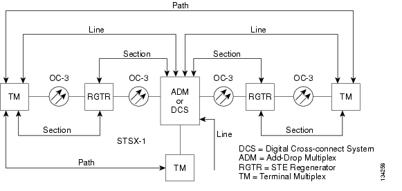
SONET Layers
SONET divides the overhead and transport functions into three layers:
•
•
•
These three layers are associated with both the physical equipment that segments the network and the bytes of information that flows through the network elements. Figure B-3 shows the various layers of a typical SONET network.
Figure B-3 Section, Line and Path Network Layers
The overhead layers are described in Table B-2.
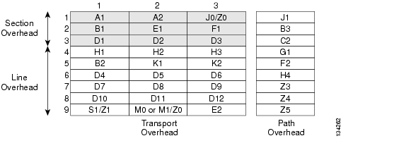
Section Overhead
The Section Overhead is found in the first three rows of Columns 1 through 9 (see Figure B-4). Table B-3 lists and defines the various Section Overhead bytes.
Figure B-4 Section Overhead Bytes within Rows 1 to 3 of Transport Overhead
Line Overhead
The Line Overhead is found in Rows 4 to 9 of Columns 1 through 9 (see Figure B-5). Table B-4 lists and defines the various Line Overhead bytes.
Figure B-5 Line Overhead Bytes in Rows 4 to 9 of Transport Overhead
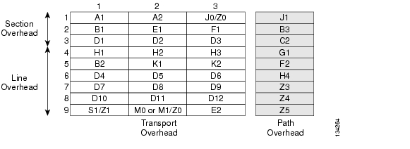
STS-1 Path Overhead
The STS-1 Path Overhead is found in Rows 1 to 9 of the first column of the STS-1 SPE (see Figure B-6). Table B-5 lists and defines the Path Overhead bytes.
Figure B-6 Path Overhead in Rows 1 to 9
Note
SPE Values
Table B-6 lists and describes the type of STS-1 SPE values.
VT Path Overhead
VT Path Overhead (VT POH) provides communication between the point of creation of a VT SPE and its point of disassembly. Four bytes (V5, J2, Z6, and Z7) are allocated for VT POH. The first byte of a VT SPE (i.e., the byte in the location pointed to by the VT Payload Pointer) is the V5 byte, while the J2, Z6, and Z7 bytes occupy the corresponding locations in the subsequent 125 microsecond frames of the VT Super-frame.
The V5 byte provides the same functions for VT paths that the B3, C2, and G1 bytes provide for STS paths; namely error checking, signal label, and path status.
SONET Multiplexing
SONET supports two multiplexing schemes:
•
•
Asynchronous Multiplexing
Asynchronous multiplexing uses multiple stages. Signals such as asynchronous DS-1s are multiplexed, extra bits are added (bit-stuffing) to account for the variations of each individual stream, and are combined with other bits (framing bits) to form a DS2 stream. Bit-stuffing is used again to multiplex up to DS-3. DS-3s are multiplexed up to higher rates in the same manner. At the higher asynchronous rate, they cannot be accessed without demultiplexing. When these signals are multiplexed to carry DS-3 signals, the signal consists of a combination of the following payloads:
•
•
•
M13 Format
M13 multiplex provides a digital interface between the DS-1 and DS-3 signal levels. M13 takes 28 DS-1 signals and combines them into a single DS-3 using a two-step process. In step one, 4 DS-1 signals are multiplexed using pulse stuffing synchronization to reach a 6.312 Mb/s DS-2 signal. Bit multiplexing is used and the bits are interleaved according to the input numbering order. The second step multiplexes 7 of the DS-2 signals using pulse stuffing synchronization to generate the DS-3 signal. Demultiplexing is also accomplished in a two-step process. In the first step, a DS-3 signal is decomposed into 7 DS-2 signals. In the second step, each of the DS-2 signals is decomposed into 4 DS-1 signals.
Synchronous Multiplexing
Synchronous multiplexing is the SONET process used when multiple lower-order path-layer signals are adapted into a higher-order path signal, or when the higher-order path signals are adapted into the Line Overhead. The multiplexing principles of SONET are:
•
•
•
•
Figure B-7 shows the basic multiplexing structure of SONET. Any type of service, ranging from voice to high-speed data and video, can be accepted by various types of service adapters. A service adapter maps the signal into the payload envelope of the STS-1 or virtual tributary (VT). New services and signals can be transported by adding new service adapters at the edge of the SONET network.
Figure B-7 SONET Multiplexing Hierarchy
Except for concatenated signals, all inputs are eventually converted to a base format of a synchronous STS-1 signal (51.84 Mb/s or higher). Lower speed inputs such as DS1s are first bit- or byte-multiplexed into virtual tributaries. Several synchronous STS-1s are then multiplexed together in either a single- or two-stage process to form an electrical STS-N signal (N = 1 or more).
STS multiplexing is performed at the Byte Interleave Synchronous Multiplexer. Basically, the bytes are interleaved together in a format such that the low-speed signals are visible. No additional signal processing occurs except a direct conversion from electrical to optical to form an OC-N signal.
SONET Network Configurations
Point-to-Point
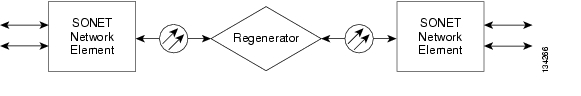
The SONET multiplexer acts as a concentrator of DS-1s as well as other tributaries. Its simplest deployment involves two terminal multiplexers linked by fiber with or without a regenerator in the link. This implementation represents the simplest SONET configuration.
In the configuration shown in Figure B-8, the SONET path and the Service path (DS-1 or DS-3 links end-to-end) are identical and this synchronous island can exist within an asynchronous network world. Point-to-point service path connections can span across the whole network and will always originate and terminate in a multiplexer.
Figure B-8 Point-to-Point Network Configuration
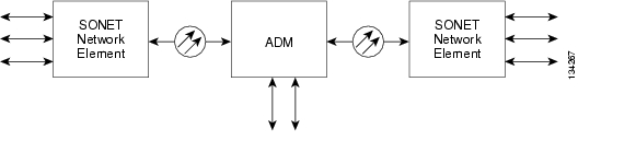
Point-to-Multipoint
The point-to-multipoint (linear add/drop) configuration shown in Figure B-9 includes adding and drop/ping circuits along the way. The SONET add/drop multiplexer (ADM) is a unique network element specifically designed for this task. It avoids the current cumbersome network architecture of demultiplexing, cross-connecting, adding and dropping channels, and than re-multiplexing. The ADM is typically placed along a SONET link to facilitate adding and dropping tributary channels at intermediate points in the network.
Figure B-9 Point-to-Multipoint Configuration
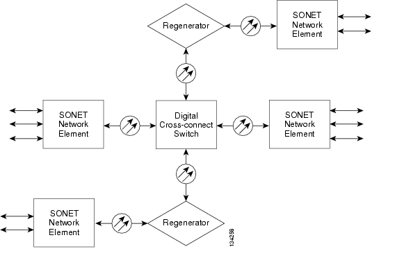
Hub
The hub configuration accommodates unexpected growth and change more easily than simple point-to-point networks. The hub configuration shown in Figure B-10 concentrates traffic at a central site and allows easy re-provisioning of the circuits. There are two possible implementations of this type of network:
•
•
Figure B-10 Hub Architecture
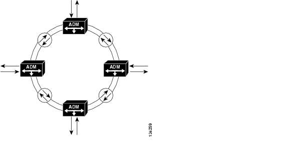
Ring
The SONET building block for a ring configuration is the ADM. Multiple ADMs can be put into a ring configuration for either bi-directional or unidirectional traffic as shown in Figure B-11. The main advantage of the ring topology is its survivability; if a fiber cable is cut, the multiplexers have the intelligence to send the services affected via an alternate path through the ring without interruption.
The demand for survivable services, diverse routing of fiber facilities, flexibility to rearrange services to alternate serving nodes, as well as automatic restoration within seconds, have made rings a popular SONET topology.
Figure B-11 Ring Architecture
Benefits of SONET
The transport network using SONET provides much more powerful networking capabilities than existing asynchronous systems. The key benefits provided by SONET include the following:
Pointers
As a result of SONET transmission, the network's clocks are referenced to a highly stable reference point. Therefore, the need to align the data streams or synchronize clocks is unnecessary. Therefore, a lower rate signal such as DS1 is accessible, and demultiplexing is not needed to access the bitstreams. Also, the signals can be stacked together without bit stuffing.
For those situations in which reference frequencies may vary, SONET uses pointers to allow the streams to "float" within the payload envelope. Synchronous clocking is the key to pointers. It allows a very flexible allocation and alignment of the payload within the transmission envelope.
Reduced Back-to-Back Multiplexing
Separate M13 multiplexers (DS-1 to DS-3) and fiber optic transmission system terminals are used to multiplex a DS-1 signal to a DS-2, DS-2 to DS-3, and then DS-3 to an optical line rate. The next stage is a mechanically integrated fiber/multiplex terminal.
In the existing asynchronous format, care must be taken when routing circuits in order to avoid multiplexing and demultiplexing too many times since electronics (and their associated capital cost) are required every time a DS-1 signal is processed. With SONET, DS-1s can be multiplexed directly to the OC-N rate. Because of synchronization, an entire optical signal doesn't have to be demultiplexed, only the VT or STS signals that need to be accessed.
Optical Interconnect
Because of different optical formats among vendors' asynchronous products, it's not possible to optically connect one vendor's fiber terminal to another. For example, one manufacturer may use 417 Mb/s line rate, another 565 Mb/s.
A major SONET value is that it allows mid-span meet with multi-vendor compatibility. Today's SONET standards contain definitions for fiber-to-fiber interfaces at the physical level. They determine the optical line rate, wavelength, power levels, pulse shapes, and coding. Current standards also fully define the frame structure, overhead, and payload mappings. Enhancements are being developed to define the messages in the overhead channels to provide increased
OAM&P Functionality
SONET allows optical interconnection between network providers regardless of who makes the equipment. The network provider can purchase one vendor's equipment and conveniently interface with other vendors' SONET equipment at either the different carrier locations or customer premises sites. Users may now obtain the OC-N equipment of their choice and meet with their network provider of choice at that OC-N level.
Multipoint Configurations
The difference between point-to-point and multipoint systems was shown previously in this appendix. Most existing asynchronous systems are only suitable for point-to-point, whereas SONET supports a multipoint or hub configuration.
A hub is an intermediate site from which traffic is distributed to three or more spurs. The hub allows the four nodes or sites to communicate as a single network instead of three separate systems. Hubbing reduces requirements for back-to-back multiplexing and demultiplexing, and helps realize the benefits of traffic grooming.
Network providers no longer need to own and maintain customer-located equipment. A multi-point implementation permits OC-N interconnects or midspan meet, allowing network providers and their customers to optimize their shared use of the SONET infrastructure.
Convergence of Voice, Data, and Video
Convergence is the trend toward delivery of voice, data, and video through diverse transmission and switching systems that supply high-speed transportation over any medium to any location. With its modular, service-independent architecture, SONET provides vast capabilities in terms of service flexibility.
Grooming
Grooming refers to either consolidating or segregating traffic to make more efficient use of the facilities. Consolidation means combining traffic from different locations onto one facility.
Segregation is the separation of traffic. With existing systems, the cumbersome technique of back hauling might be used to reduce the expense of repeated multiplexing and demultiplexing.
Grooming eliminates inefficient techniques like back hauling. It's possible to groom traffic on asynchronous systems, however to do so requires expensive back-to-back configurations and manual DSX panels or electronic cross-connects. By contrast, a SONET system can segregate traffic at either an STS-1 or VT level to send it to the appropriate nodes.
Grooming can also provide segregation of services. For example, at an interconnect point, an incoming SONET line may contain different types of traffic, such as switched voice, data, or video. A SONET network can conveniently segregate the switched and non-switched traffic.
Reduced Cabling and Use of DSX Panels
Asynchronous systems are dominated by back-to-back terminals because the asynchronous Fiber optic transmission system architecture is inefficient for other than point-to-point networks. Excessive multiplexing and demultiplexing are used to transport a signal from one end to another, and many bays of DSX-1 cross-connect and DSX-3 panels are required to interconnect the systems. Associated expenses are the panel, bays, cabling, the labor installation, and the inconveniences of increased floor space and congested cable racks.
The corresponding SONET system allows a hub configuration, reducing the need for back-to-back terminals. Grooming is performed electronically so DSX panels are not used except when required to interface with existing asynchronous equipment.
Enhanced OAM&P
SONET allows integrated network OAM&P (also known as OA&M), in accordance with the philosophy of single-ended maintenance. In other words, one connection can reach all network elements (within a given architecture); separate links are not required for each network element. Remote provisioning provides centralized maintenance and reduced travel for maintenance personnel, which translates to expense savings.
Enhanced Performance Monitoring
Substantial overhead information is provided in SONET to allow quicker troubleshooting and detection of failures before they degrade to serious levels.
Convergence of SONET and SDH Hierarchies
SONET and SDH converge at SONET's 52 Mb/s base level, defined as STM-0 or "Synchronous Transport Module-0". The base level for SDH is STM-1 which is equivalent to SONET's STS-3 (3 x 51.84 Mb/s = 155.5 Mb/s). Higher SDH rates are STM-4 (622 Mb/s) and STM-16 (2.5 Gb/s). STM-64 (10 Gb/s) has also been defined.
Multiplexing is accomplished by combining (or interleaving) multiple lower-order signals (1.5 Mb/s, 2 Mb/s, etc.) into higher-speed circuits (52 Mb/s, 155 Mb/s, etc.). By changing the SONET standard from bit-interleaving to byte-interleaving, it became possible for SDH to accommodate both transmission hierarchies.
SDH
Following development of the SONET standard by ANSI, the CCITT undertook to define a synchronization standard that would address inter-working between the CCITT and ANSI transmission hierarchies. That effort culminated in 1989 with CCITT's publication of the Synchronous Digital Hierarchy (SDH) standards. Synchronous Digital Hierarchy is a world standard, and as such, SONET can be considered a subset of SDH.
Transmission standards in the U.S., Canada, Korea, Taiwan, and Hong Kong (ANSI) and the rest of the world (ITU-T, formerly CCITT) evolved from different basic rate signals in the non-synchronous hierarchy. ANSI Time Division Multiplexing (TDM) combines twenty-four 64-kbps channels (DS0s) into one 1.54-Mb/s DS1 signal. ITU-T TDM multiplexes thirty-two 64-kbps channels (E0s) into one 2.048 Mb/s E-1 signal.
The issues between ITU-T and ANSI standards-makers involved how to efficiently accommodate both the 1.5-Mb/s and the 2-Mb/s non-synchronous hierarchies in a single synchronization standard. The agreement reached specifies a basic transmission rate of 52 Mb/s for SONET and a basic rate of 155 Mb/s for SDH.
Asynchronous and Synchronous Tributaries
SDH does away with a number of the lower multiplexing levels, allowing non-synchronous 2-Mb/s tributaries to be multiplexed to the STM-1 level in a single step. SDH recommendations define methods of subdividing the payload area of an STM-1 frame in various ways so that it can carry combinations of synchronous and asynchronous tributaries. Using this method, synchronous transmission systems can accommodate signals generated by equipment operating from various levels of the non-synchronous hierarchy.
Synchronous and non-synchronous line rates and the relationships between each are shown in Table B-7 and Table B-8.
![]()
![]()
![]()
![]()
![]()
![]()
![]()
![]()
Posted: Tue Nov 27 10:49:45 PST 2007
All contents are Copyright © 1992--2007 Cisco Systems, Inc. All rights reserved.
Important Notices and Privacy Statement.