|
|

Table Of Contents
Autonegotiation, Flow Control, and Frame Buffering
Ethernet Link Integrity Support
Enhanced State Model for Ethernet and SONET/SDH Ports
IEEE 802.1Q CoS and IP ToS Queuing
CE-100T-8 SONET Circuits and Features
Available Circuit Sizes and Combinations
CE-100T-8 Pools and STS/VT Allocation Tab
CE-100T-8 VCAT Characteristics
CE-100T-8 POS Encapsulation, Framing, and CRC
CE-100T-8 Loopback, J1 Path Trace, and SONET Alarms
CE-100T-8 Ethernet Operation
This chapter covers the operation of the CE-100T-8 (Carrier Ethernet) card supported on the ONS 15454 (15454-CE-100T-8). A CE-100T-8 card is also supported on the ONS 15310 (15310-CE-100T-8). Provisioning is done through Cisco Transport Controller (CTC) or Transaction Language One (TL1). Cisco IOS is not supported on the CE-100T-8 card.
For Ethernet card specifications, refer to the Cisco ONS 15454 Reference Manual. For step-by-step Ethernet card circuit configuration procedures, refer to the Cisco ONS 15454 Procedure Guide. Refer to the Cisco ONS SONET TL1 Command Guide for TL1 provisioning commands.
Chapter topics include:
•
CE-100T-8 SONET Circuits and Features
CE-100T-8 Overview
The CE-100T-8 is a Layer 1 mapper card with eight 10/100 Ethernet ports. It maps each port to a unique SONET circuit in a point-to-point configuration. Figure 21-1 illustrates a sample CE-100T-8 application. In this example, data traffic from the Fast Ethernet port of a switch travels across the point-to-point circuit to the Fast Ethernet port of another switch.
Figure 21-1 CE-100T-8 Point-to-Point Circuit
The CE-100T-8 cards allow you to provision and manage an Ethernet private line service like a traditional SONET line. CE-100T-8 card applications include providing carrier-grade Ethernet private line services and high-availability transport.
The CE-100T-8 card carries any Layer 3 protocol that can be encapsulated and transported over Ethernet, such as IP or IPX. The Ethernet frame from the data network is transmitted on the Ethernet cable into the standard RJ-45 port on a CE-100T-8 card. The CE-100T-8 card transparently maps Ethernet frames into the SONET payload using packet-over-SONET (POS) encapsulation. The POS circuit with its encapsulated Ethernet inside is then multiplexed onto an OC-N card like any other SONET STS. When the payload reaches the destination node, the process is reversed and the data is transmitted from the standard RJ-45 port in the destination CE-100T-8 card onto the Ethernet cable and data network. The POS process is covered in detail in Chapter 19, "POS on ONS Ethernet Cards."
The CE-100T-8 card supports ITU-T G.707 and Telcordia GR-253 based standards for SONET. It offers a carrier-class level of features and reliability. This includes errorless (0-msec impact on traffic) reprovisioning. When circuit or port provisioning takes place, this operation does not affect the performance of other ports and circuit configurations that are already established on the card.
Software upgrades are errorless. However when the CE-100T-8 firmware is upgraded, the upgrade has an effect on traffic similar to the effect of a hard reset on the CE-100T-8. A software upgrade or a firmware upgrade does not affect the existing provisioning of the ports and circuits on the CE-100T-8 card.
Span upgrades are hitless. Protection and maintenance switches are also hitless.
The CE-100T-8 offers full TL1-based provisioning capability. Refer to the Cisco ONS SONET TL1 Command Guide for CE-100T-8 TL1 provisioning commands.
CE-100T-8 Ethernet Features
The CE-100T-8 card has eight front-end Ethernet ports which use standard RJ-45 connectors for 10BASE-T Ethernet/100BASE-TX Ethernet media. Ethernet Ports 1 through 8 each map to a POS port with a corresponding number. The console port on the CE-100T-8 card is not functional.
The CE-100T-8 cards forward valid Ethernet frames unmodified over the SONET network. Information in the headers is not affected by the encapsulation and transport. For example, included IEEE 802.1Q information will travel through the process unaffected.
The ONS 15454 CE-100T-8 and the ONS 15310 CE-100T-8 support maximum Ethernet frame sizes of 1600 bytes including the CRC. The MTU size is not configureable and is set at a 1500 byte maximum (standard Ethernet MTU). Baby giant frames in which the standard Ethernet frame is augmented by 802.1 Q tags or MPLS tags are also supported. Full Jumbo frames are not supported.
The CE-100T-8 cards discard certain types of erroneous Ethernet frames rather than transport them over SONET. Erroneous Ethernet frames include corrupted frames with cyclic redundancy check (CRC) errors and undersized frames that do not conform to the minimum 64-byte length Ethernet standard.
Note
Autonegotiation, Flow Control, and Frame Buffering
On the CE-100T-8, Ethernet link autonegotiation is on by default. The user can also set the link speed, duplex, and flow control manually under the card-level Provisioning tab of CTC.
The CE-100T-8 supports IEEE 802.3x flow control and frame buffering to reduce data traffic congestion. Flow control is on by default.
To prevent over-subscription, buffer memory is available for each port. When the buffer memory on the Ethernet port nears capacity, the CE-100T-8 uses IEEE 802.3x flow control to transmit a pause frame to the attached Ethernet device. Flow control and autonegotiation frames are local to the Fast Ethernet interfaces and the attached Ethernet devices. These frames do not continue through the POS ports.
The CE-100T-8 card has symmetric flow control and proposes symmetric flow control when autonegotiating flow control with attached Ethernet devices. Symmetric flow control allows the CE-100T-8 cards to respond to pause frames sent from external devices and to send pause frames to external devices.
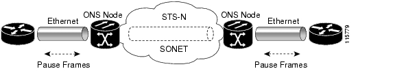
The pause frame instructs the source to stop sending packets for a specific period of time. The sending station waits the requested amount of time before sending more data. Figure 21-2 illustrates pause frames being sent and received by CE-100T-8 cards and attached switches.
Figure 21-2 Flow Control
This flow-control mechanism matches the sending and receiving device throughput to that of the bandwidth of the STS circuit. For example, a router might transmit to the Ethernet port on the CE-100T-8 card. This particular data rate might occasionally exceed 51.84 Mbps, but the SONET circuit assigned to the CE-100T-8 port might be only STS-1 (51.84 Mbps). In this example, the CE-100T-8 sends out a pause frame and requests that the router delay its transmission for a certain period of time. With flow control and a substantial per-port buffering capability, a private line service provisioned at less than full line rate capacity (STS-1) is efficient because frame loss can be controlled to a large extent.
Ethernet Link Integrity Support
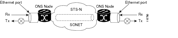
The CE-100T-8 supports end-to-end Ethernet link integrity ( Figure 21-3). This capability is integral to providing an Ethernet private line service and correct operation of Layer 2 and Layer 3 protocols on the attached Ethernet devices.
End-to-end Ethernet link integrity means that if any part of the end-to-end path fails, the entire path fails. It disables the Ethernet port on the CE-100T-8 card if the remote Ethernet port is unable to transmit over the SONET network or if the remote Ethernet port is disabled.
Failure of the entire path is ensured by turning off the transmit pair at each end of the path. The attached Ethernet devices recognize the disabled transmit pair as a loss of carrier and consequently an inactive link or link fail.
Figure 21-3 End-to-End Ethernet Link Integrity Support
Note
Enhanced State Model for Ethernet and SONET/SDH Ports
The CE-100T-8 supports the Enhanced State Model (ESM) for the Ethernet ports, as well as for the SONET/SDH circuit. For more information about the ESM, see the "Enhanced State Model" appendix in the ONS 15454 SONET Reference Manual or the ONS 15454 SDH Reference Manual.
The Ethernet ports can be set to the ESM service states including the In-Service, Automatic In-Service (IS,AINS) administrative state. IS,AINS initially puts the port in the Out-of-Service and Autonomous, Automatic In-Service (OOS-AU,AINS) state. In this service state, alarm reporting is suppressed, but traffic is carried and loopbacks are allowed. After the soak period passes, the port changes to In-Service and Normal (IS-NR). Raised fault conditions, whether their alarms are reported or not, can be retrieved on the CTC Conditions tab or by using the TL1 RTRV-COND command.
Two Ethernet port alarms/conditions, CARLOSS and TPTFAIL, can prevent the port from going into service. This occurs even though alarms are suppressed when a CE-100T-8 circuit is provisioned with the Ethernet ports set to the IS,AINS state, because the CE-100T-8 link integrity function is active and ensures that the links at both ends are not enabled until all SONET and Ethernet errors along the path are cleared. As long as the link integrity function keeps the end-to-end path down, both ports will have at least one of the two conditions needed to suppress the AINS-to-IS transition. Therefore, the ports will remain in the AINS state with alarms suppressed.
ESM also applies to the SONET/SDH circuits of the CE-100T-8 card. If the SONET/SDH circuit is set up in IS,AINS state and the Ethernet error occurs before the circuit transitions to IS, then link integrity will also prevent the circuit transition to the IS state until the Ethernet port errors are cleared at both ends. The service state will be OOS-AU,AINS as long as the administrative state is IS,AINS. When there are no Ethernet or SONET errors, link integrity enables the Ethernet port at each end. Simultaneously, the AINS countdown begins as normal. If no additional conditions occur during the time period, each port transitions to the IS-NR state. During the AINS countdown, the soak time remaining is available in CTC and TL1. The AINS soaking logic restarts from the beginning if a condition appears again during the soak period.
A SONET/SDH circuit provisioned in the IS,AINS state remains in the initial Out-of-Service (OOS) state until the Ethernet ports on each end of the circuit transition to the IS-NR state. The SONET/SDH circuit transports Ethernet traffic and counts statistics when link integrity turns on the Ethernet port, regardless of whether this AINS-to-IS transition is complete.
IEEE 802.1Q CoS and IP ToS Queuing
The CE-100T-8 references IEEE 802.1Q class of service (CoS) thresholds and IP type of service (ToS) (IP Differentiated Services Code Point [DSCP]) thresholds for priority queueing. CoS and ToS thresholds for the CE-100T-8 are provisioned on a per port level. This allows the user to provide priority treatment based on open standard quality of service (QoS) schemes already existing in the data network attached to the CE-100T-8. The QoS treatment is applied to both Ethernet and POS ports.
Any packet or frame with a priority greater than the set threshold is treated as priority traffic. This priority traffic is sent to the priority queue instead of the normal queue. When buffering occurs, packets on the priority queue preempt packets on the normal queue. This results in lower latency for the priority traffic, which is often latency-sensitive traffic, such as VoIP.
Because these priorities are placed on separate queues, the priority queuing feature should not be used to separate rate-based CIR/EIR marked traffic (sometimes done at a Metro Ethernet service provider edge). This could result in out-of-order packet delivery for packets of the same application, which would cause performance issues with some applications.
For an IP ToS-tagged packet, the CE-100T-8 can map any of the 256 priorities specified in IP ToS to priority or best effort. The user can configure a different ToS on CTC at the card-level view under the Provisioning > Ether Ports tabs. Any ToS class higher than the class specified in CTC is mapped to the priority queue, which is the queue geared towards low latency. By default, the ToS is set to 255, which is the highest ToS value. This results in all traffic being treated with equal priority by default.
Table 21-3 shows which values are mapped to the priority queue for sample IP ToS settings. (ToS settings span the full 0 to 255 range, but only selected settings are shown.)
Table 21-1 IP ToS Priority Queue Mappings
255 (default)
None
250
251-255
150
151-255
100
101-255
50
51-255
0
1-255
For a CoS-tagged frame, the CE-100T-8 can map the eight priorities specified in CoS to priority or best effort. The user can configure a different CoS on CTC at the card-level view under the Provisioning > Ether Ports tabs. Any CoS class higher than the class specified in CTC is mapped to the priority queue, which is the queue geared towards low latency. By default, the CoS is set to 7, which is the highest CoS value. This results in all traffic being treated with equal priority by default.
Table 21-3 shows which values are mapped to the priority queue for CoS settings.
Table 21-2 CoS Priority Queue Mappings
7 (default)
none
6
7
5
6, 7
4
5, 6, 7
3
4, 5, 6, 7
2
3, 4, 5, 6, 7
1
2, 3, 4, 5, 6, 7
0
1, 2, 3, 4, 5, 6, 7
Ethernet frames without VLAN tagging use ToS-based priority queueing if both ToS and CoS priority queueing is active on the card. The CE-100T-8 card's ToS setting must be lower than 255 (default) and the CoS setting lower than 7 (default) for CoS and ToS priority queueing to be active. A ToS setting of 255 (default) disables ToS priority queueing, so in this case the CoS setting would be used.
Ethernet frames with VLAN tagging use CoS-based priority queueing if both ToS and CoS are active on the card. The ToS setting is ignored. CoS based priority queueing is disabled if the CoS setting is the 7 (default), so in this case the ToS setting would be used.
If the CE-100T-8 card's ToS setting is 255 (default) and the CoS setting is 7 (default), priority queueing is not active on the card, and data gets sent to the default normal traffic queue. Also if data is not tagged with a ToS value or a CoS value before it enters the CE-100T-8 card, it gets sent to the default normal traffic queue.
Note
Note
RMON and SNMP Support
The CE-100T-8 card features remote monitoring (RMON) that allows network operators to monitor the health of the network with a network management system (NMS). The CE-100T-8 uses the ONG RMON. The ONG RMON contains the statistics, history, alarms, and events MIB groups from the standard RMON MIB. A user can access RMON threshold provisioning through TL1 or CTC. For RMON threshold provisioning with CTC, see the Cisco ONS 15454 Procedure Guide (NTP-A279) and the Cisco ONS 15454 Troubleshooting Guide. For TL1 information, see the Cisco ONS SONET TL1 Command Guide.
Statistics and Counters
The CE-100T-8 has a full range of Ethernet and POS statistics under Performance > Ether Ports or Performance > POS Ports.
CE-100T-8 SONET Circuits and Features
The CE-100T-8 has eight POS ports, numbered one through eight, which are exposed to management with CTC or TL1. Each POS port is statically mapped to a matching Ethernet port. By clicking the card-level Provisioning tab > POS Ports tab, the user can configure the Administrative State, Framing Type, and Encapsulation Type. By clicking the card-level Performance tab > POS Ports tab, the user can view the statistics, utilization, and history for the POS ports.
Available Circuit Sizes and Combinations
Each POS port terminates an independent contiguous SONET concatenation (CCAT) or virtual SONET concatenation (VCAT). The SONET circuit is created for these ports through CTC or TL1 in the same manner as a SONET circuit for a non-Ethernet line card. Table 21-3 shows the circuit sizes available for the CE-100T-8 on the ONS 15454.
Table 21-3 CE-100T-8 Supported Circuit Sizes
STS-1
STS-1-1v
VT1.5-nV (n= 1 to 64)
STS-3c
STS-1-2v
STS-1-3v
A single circuit provides a maximum of 100 Mbps of throughput, even when an STS-3c circuit, which has a bandwidth equivalent of 155 Mbps, is provisioned. This is due to the hardware restriction of the Fast Ethernet port. A VCAT circuit is also restricted in this manner. Table 21-3 shows the minimum SONET circuit sizes required for 10 Mbps and 100 Mbps wire speed service.
*STS-1-2v provides a total transport capacity of 98 Mbps.
The number of available circuits and total combined bandwidth for the CE-100T-8 depends on the combination of circuit sizes configured. Table 21-5 shows the circuit size combinations available for the CE-100T-8 on the ONS 15454.
Table 21-5 CCAT High Order Circuit Size Combinations
None
8
1
7
2
6
3
3
4
None
Table 21-6 VCAT High Order Circuit Combinations for STS-1-3v and STS-1-2v
None
4
1
3
2
2
3
1
4
None
The CE-100T-8 supports up to eight low order VCAT circuits . The available circuit sizes are VT1.5-Xv, where X is the range from 1 to 64. A maximum of four circuits are available at the largest low order VCAT circuit size, VT1.5-64v.
A user can combine CCAT high order, VCAT high order and VCAT low order circuits. The following table details the maximum density service combinations.
*This low order VCAT circuit combination is achievable if one of the first two circuits created on the card is an low order VCAT circuit. If the first two circuits created on the card are high order VCAT or CCAT, then a maximum of three low order VCAT circuits can be created on the card.
CE-100T-8 Pools and STS/VT Allocation Tab
The CE-100T-8 has four pools, each with a maximum capacity of three STSs. All VCAT circuit members must be from the same pool.
One of the four memory pools is reserved for the low order VCAT circuits, if sufficient bandwidth exists to support the high order circuits on the remaining three pools. The high order CCAT circuits use all the available capacity from a single memory pool before begining to use the capacity of a new pool. The memory pools will be allocated alternatively for the first three high order VCAT circuits if the pools have the sufficient bandwidth to support the requested circuit size. To help prevent stranding bandwidth, provision your high order VCAT circuits first to distribute them evenly.
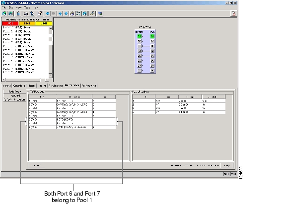
At the CTC card-level view under the Maintenance tab, the STS/VT Allocation tab displays how the provisioned circuits populate the four pools. This information can be useful in freeing up the bandwidth required for provisioning a circuit, if there is not enough existing capacity on any one pool for provisioning the desired circuit. The user can look at the distribution of the existing circuits among the four pools and decide which circuits to delete in order to free up space for the desired circuit.
Figure 21-4 CE-100T-8 STS/VT Allocation Tab
For example if a user needs to provision an STS-3c or STS-1-3v on the CE-100T-8 card shown in Figure 21-4, an STS-3c or STS-1-3v worth of bandwidth is not available from any of the four pools. The user needs to delete circuits from the same pool to free up bandwidth. If the bandwidth is available but scattered among the pools, the circuit cannot be provisioned. Looking at the POS Port Map table, the user can determine which circuits belong to which pools. The Pool and Port columns in Figure 21-4 show that port 6 and port 7 are both drawn from Pool 1, and no other circuits are drawn from Pool 1. Deleting these two STS-1 circuits will free up an STS-3c or STS-1-3v worth of bandwidth from a single pool.
If the user did not determine what circuits to delete from the table information, he might delete the STS-1 circuits on port 3, port 5 and port 6. This frees up an STS-3c or STS-1-3v worth of bandwidth but the required bandwidth is not available from a single pool, and the STS-3c or STS-1-3v circuit is not provisionable.
The POS Port table has a row for each port with three columns ( Figure 21-4). They show the port number, the circuit size and type, and the pool it is drawn from. The Pool Utilization table has four columns and shows the pool number, the type of circuits on that pool, how much of the pool's capacity is being used, and whether additional capacity is available.
CE-100T-8 VCAT Characteristics
The ML-100T-8 card and the CE-100T-8 card (both the ONS 15310-CL version and the ONS 15454 SONET/SDH version) have hardware-based support for the ITU-T G.7042 standard link capacity adjustment scheme (LCAS). This allows the user to dynamically resize a high order or low order VCAT circuit through CTC or TL1 without affecting other members of the VCG (errorless). ML-100T-8 LCAS support is high order only and is limited to a two member VCG.
The ONS 15454 SONET/SDH ML-Series card has a software-based LCAS (SW-LCAS) scheme. This scheme is also supported by both the ML-100T-8 card and both versions of the CE-100T-8, but only for circuits terminating on a ONS 15454 SONET/SDH ML-Series card.
The CE-100T-8 card allows independent routing and protection preferences for each member of a VCAT circuit. The user can also control the amount of VCAT circuit capacity that is fully protected, unprotected or if the circuit is on a bidirectional line switched ring (BLSR), uses protection channel access (PCA). Alarms are supported on a per-member as well as per virtual concatenation group (VCG) basis.
Note
CE-100T-8 POS Encapsulation, Framing, and CRC
The CE-100T-8 uses Cisco EoS LEX (LEX). LEX is the primary encapsulation of ONS Ethernet cards. In this encapsulation the protocol field is set to the values specified in Internet Engineering Task Force (IETF) Request For Comments (RFC) 1841. The user can provision GPF-F framing (default) or high-level data link control (HDLC) framing. With GFP-F framing, the user can also configure a 32-bit CRC (the default) or no CRC (none). When LEX is used over GFP-F it is standard Mapped Ethernet over GFP-F according to ITU-T G.7041. HDLC framing provides a set 32-bit CRC. For more details on the interoperability of ONS Ethernet cards, including information on encapsulation, framing, and CRC, see the "POS on ONS Ethernet Cards" chapter.
The CE-100T-8 card supports GFP-F null mode. GFP-F CMFs are counted and discarded.
CE-100T-8 Loopback, J1 Path Trace, and SONET Alarms
The CE-100T-8 card supports terminal and facility loopbacks. It also reports SONET alarms and transmits and monitors the J1 Path Trace byte in the same manner as OC-N cards. Support for path termination functions includes:
•
•
•
•
•
•
•
•
•
•
![]()
![]()
![]()
![]()
![]()
![]()
![]()
![]()
Posted: Mon Dec 3 03:00:05 PST 2007
All contents are Copyright © 1992--2007 Cisco Systems, Inc. All rights reserved.
Important Notices and Privacy Statement.