cc/td/doc/product/ong/15400/r34docs
hometocprevnextglossaryfeedbacksearchhelp
PDF

Table Of Contents

Error Messages Troubleshooting

4.1 Circuit Errors

4.1.1 Circuit Source Error

4.1.2 Circuit Destination Error

4.1.3 Circuit Destroy Failed

4.1.4 Auto-Ranging Circuit Creation

4.1.5 Node Selection Error

4.1.6 Circuit Creation Error

4.1.7 Error While finishing Circuit Creation

4.1.8 Error Adding Drop

4.1.9 Error Applying Changes

4.1.10 Error Deleting Circuit Drop

4.1.11 Error

4.1.12 Circuit Deletion Error

4.1.13 Circuit Attributes Error

4.1.14 Error Validating Slot Number

4.1.15 Error Validating Port Number

4.1.16 Circuit Route Constraints Error

4.2 BLSR Errors

4.2.1 Cannot Delete Ring

4.2.2 Invalid Ring ID

4.2.3 Error

4.2.4 Error Applying Changes

4.2.5 Duplicate Node ID

4.2.6 BLSR Error


Error Messages Troubleshooting


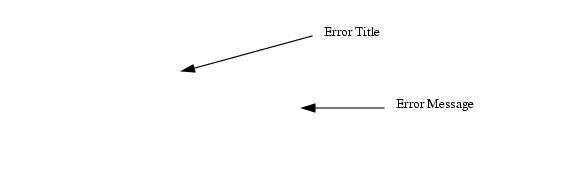
This chapter explains how to troubleshoot commonly-encountered error messages for the Cisco ONS 15454. The error dialogue consists of two parts: the error title and the error message.

Figure 4-1 An error dialog box

Sections in this chapter are divided into error type (for example, circuit errors, BLSR errors, etc.) followed by the error title(s) for each dialog.

4.1 Circuit Errors

This section includes circuit-related error messages. The following headings show the error title (e.g. 4.1.x). If the same error title has multiple error messages, the error messages are listed as subheadings (e.g. 4.1.x.x)

4.1.1 Circuit Source Error

The following messages appear in the Circuit Source Error dialog box. For detailed circuit creation instructions, refer to the Cisco ONS 15454 Procedure Guide.

4.1.1.1 Exception: Source node must be selected

This error message appears if you click Next on the Circuit Source Creation dialog without entering a source node.


Step 1 Click OK to close the error dialog.

Step 2 Choose the primary source node for the circuit.

Step 3 Choose the Slot, Port, STS and VT if applicable for the primary source.

Step 4 Click Next.


4.1.1.2 Exception: Source is not fully specified

This error message is displayed when the source circuit is not fully defined.


Step 1 Click OK to close the error dialog.

Step 2 Choose the primary source node for the circuit.

Step 3 Choose the Slot, Port, STS and VT if applicable for the primary source.

Step 4 Click Next.


4.1.1.3 Exception: Secondary Source is not fully specified

This error message is displayed when the secondary circuit is not fully defined.


Step 1 Click OK to close the dialog.

Step 2 Choose the secondary source node for the circuit.

Step 3 Choose the Slot, Port, STS and VT if applicable for the secondary source.

Step 4 Click Next.


4.1.1.4 Exception: Sources can't be identical

This error occurs if identical primary and secondary source circuits are selected.


Step 1 Click OK to close the error dialog.

Step 2 Click the Use Secondary Source button.

Step 3 Choose a Slot, Port and STS or VT number, if applicable, that is not the same as the primary circuit.

Step 4 Click Next.


4.1.2 Circuit Destination Error

The following error messages appear in the Circuit Destination Error dialog box.

4.1.2.1 Exception: Destination node must be selected

This error message appears if you do not select a destination node and try to proceed to the next circuit creation screen.


Step 1 Click OK to close the error dialog.

Step 2 Choose the primary destination node for the circuit.

Step 3 Choose the Slot, Port, STS and VT if applicable for the primary destination.

Step 4 Click Next.


4.1.2.2 Exception: Destination is not fully specified

This error message is displayed when the destination circuit is not fully defined.


Step 1 Click OK to close the error dialog.

Step 2 Choose the primary destination node for circuit.

Step 3 Choose the Slot, Port, STS and VT if applicable for the primary source.

Step 4 Click Next.


4.1.2.3 Exception: Secondary Destination is not fully specified

This error message is displayed when the secondary destination circuit is not fully defined.


Step 1 Click OK to close the error dialog.

Step 2 Choose the secondary destination node for the circuit.

Step 3 Choose the Slot, Port, STS and VT if applicable for the secondary destination.

Step 4 Click Next.


4.1.2.4 Exception: Destinations can't be identical

This error occurs if when primary and secondary circuit destinations are selected.


Step 1 Click OK to close the error dialog.

Step 2 Click the "Use Secondary Destination" button.

Step 3 Choose a Slot, Port and STS or VT number if applicable that is not the same as the primary circuit.

Step 4 Click Next.


4.1.3 Circuit Destroy Failed

The following messages appear in the Circuit Destroy Failed dialog box.

These errors occur when a circuit is being deleted and CTC loses DCC or gateway LAN communication to the node.

4.1.3.1 CmsCommFailException: < node-ip address > Communications error (COMM_FAILURE)  while attempting to set the CircuitModel.delete attribute

CTC cannot communicate to all the nodes in the network where the circuit must traverse. CTC must be able to communicate with all of the nodes before it is safe to delete the circuits.


Step 1 Click OK to close the error dialog.

Step 2 Go to the network view and verify that none of the nodes are greyed out

Step 3 Click the Alarms tab.

Step 4 Search for alarms to indicate that there is a DCC termination failure.

Step 5 If a DCC termination failure is present, reprovision the DCC channel or check for a broken fiber between the two nodes.

Step 6 If a DCC termination failure is not present, access a command prompt from CTC and run the ping command to the nodes the circuit traverses. See the "Ping the ONS 15454" procedure on page 1-48.

Step 7 Repeat Step 6 as needed to verify that CTC can successfully run the ping command to each of the nodes.

Step 8 Click the Circuit tab in either the network view or node view.

Step 9 Highlight the circuit that you need to delete.

Step 10 Click the Delete button.

Step 11 Click the Yes button when the circuit deletion warning dialogue appears.

Step 12 Delete as many circuits as necessary.


4.1.3.2 CmsCommFailException: < node-ip address > The Node was not initialized while attempting to set the CircuitModel.delete attribute

CTC cannot communicate with all the nodes in the network where the circuit must traverse. CTC must be able to communicate with all of the nodes before it is safe to delete the circuits.


Step 1 Click OK to close the error dialog.

Step 2 Go to the network view and verify that none of the nodes are greyed out

Step 3 Click the Alarms tab.

Step 4 Search for an alarms to indicate that there is a DCC termination failure.

Step 5 If a termination failure is present, reprovision the SDCC channel or check for a broken fiber between the two nodes.

Step 6 If an SDCC termination failure is not present, run the ping command to the nodes the circuit traverses. See the "Ping the ONS 15454" procedure on page 1-48.

Step 7 Verify that CTC can successfully run the ping command to each of the nodes.

Step 8 Click the Circuit tab in either the network or node view.

Step 9 Highlight the circuit that you want to delete.

Step 10 Click the Delete button.

Step 11 Click the Yes button when the circuit deletion warning dialogue appears.

Step 12 Delete as many circuits as necessary.


4.1.4 Auto-Ranging Circuit Creation

The following messages appear in the Auto-Ranging Circuit Creation dialog box.

4.1.4.1 Unable to provision circuit Unexpected exception encountered Attempts to access a VtAdit that has been destroyed.CmsObjectNotExistException: Attempts to access a VtAdit that has been destroyed.

This error occurs when routing a group of VT circuits over an existing VT tunnel.

This error typically occurs when a CTC session attempts to access a VT-grooming STS Path that has been deleted by another CTC user (or session).


Step 1 Click OK to clear the error dialog.

Step 2 Cancel the circuit dialogue.

Step 3 Restart the circuit dialogue.

Step 4 Continue to provision the original circuit.


4.1.4.2  NoRoute: ComputerRouteInMixedDomains: No Route found with given  requirements.

This error occurs when CTC attempts to create auto- ranged circuits but it cannot provision a route for the subsequent circuits.One of the protection paths is fully blocked because there is no available bandwidth after the Nth circuit is attempted.

Circuit routing can fail for one of the following reasons:

There is no connectivity between the source and drop of the circuit.

The network topology has not been fully discovered.

Sufficient network bandwidth is not available to support the requested circuit.

Path protection was requested and there is no end-to-end protected path available.

One or more LO Tunnels were required to complete a LO circuit but a failure was encountered during the provisioning of the tunnels.

A BLSR was along the path but there was no common time slot available in the ring.

The "Route using Required Nodes/Spans" option was selected and an invalid set of constraints was  provided. Examples of invalid constraints include:

A node along the path from source to drop was "excluded" and no other path is available.

A required link along the path from source to drop was selected in the wrong direction (from drop to source).

One of the required links does not have bandwidth to support the circuit.

One of the required links for a path-protected circuit cannot be protected

If a circuit routing failure is encountered, identify the root cause of the problem among the above set of conditions. If possible, rectify the problem and re-attempt circuit provisioning.


Step 1 Click OK to clear the error dialog.

Step 2 Calculate how much available bandwidth is available on both the working and the protection path by following the steps below.

a. Go to the network view on the CTC.

b. Click on each span and then right-click the mouse button.

c. Click the Circuits label from the drop down screen. A table appears that shows the available bandwidth.

d. Make a note of the available bandwidth for each of the spans. Note the available bandwidth for both a working and a protection path.

Step 3 Click Create on the main circuit screen.

Step 4 Input the number of available circuits based on the available bandwidth into the Number of Circuits box.

Step 5 Click Next at the bottom of the screen.

Step 6 Continue to provision both the source and destination circuits.

Step 7 Click Finish on the Circuit Routing Preferences screen.


4.1.4.3  Unable to drop route ComputeRouteInMixedDomains: No Route found with given requirements NoRoute: ComputeRouteInMixedDomains: No Route found with given requirements

This error is very similar to the previous error, but applies to drop circuits only. Both of the errors can occur when a path is no longer available.

Circuit routing can fail for one of the following reasons:

There is no connectivity between the source and drop of the circuit.

The network topology has not been fully discovered.

Sufficient network bandwidth is not available to support the requested circuit.

Path protection was requested and there is no end-to-end protected path available.

One or more LO Tunnels were required to complete a LO circuit but a failure was encountered during the provisioning of the tunnels.

A BLSR was along the path but there was no common time slot available in the ring.

The "Route using Required Nodes/Spans" option was selected and an invalid set of constraints was  provided. Examples of invalid constraints include:

A node along the path from source to drop was "excluded" and no other path is available.

A required link along the path from source to drop was selected in the wrong direction (from drop to source).

One of the required links does not have bandwidth to support the circuit.

One of the required links for a path-protected circuit cannot be protected


Step 1 Click OK to clear the error dialog.

Step 2 Calculate how much available bandwidth is available on both the working and the protection path by following the steps below.

a. Go to the network view on the CTC.

b. Click on each span and then right-click the mouse button.

c. Click the Circuits label from the drop down screen. A table appears that shows the available bandwidth.

d. Make a note of the available bandwidth for each of the spans. Note the available bandwidth for both a working and a protection path.

Step 3 Click Create on the main circuit screen.

Step 4 Input the number of available circuits based on the available bandwidth into the Number of Circuits box.

Step 5 Click Next at the bottom of the screen.

Step 6 Continue to provision both the source and destination circuits.

Step 7 Click Finish on the Circuit Routing Preferences screen.


4.1.4.4  NoRoute: Unable to route VT Circuit: possible reasons: 1) VT Tunnel required and cannot route due to XCs in the path from source to destination 2) Cannot find route that satisfies given requirements

This exception occurs if a one or more lower order (LO) tunnels were required to complete a LO circuit but a failure was encountered during the provisioning of the tunnels.


Step 1 Click OK to clear the error dialog.

Step 2 Provision the LO circuit.


4.1.4.5 Exception: Source is not fully specified

This error occurs when more auto-ranged circuits than available ports or STSs are requested. For example, if a user attempts to automatically provision 15 DS3 circuits and there is only one 12-port DS3 card in the system, the error will appear after all 12 DS3 ports are utilized. The auto-ranging circuit provisioning does not automatically increment the slot for the source or destination. It does not automatically increment the port number on the OC-3 card for STS-1 circuits.


Step 1 Click OK to clear the error dialog.

Step 2 Click Back.

Step 3 Provision more ports on the system to satisfy the available auto-ranging requirements.

Step 4 Insert additional cards if slots are available.

Step 5 The installed card should reflect the type of circuit that is being added (i.e. DS-3, DS-1, etc.)

Step 6 If more slots are unavailable, the number of auto ranged circuits must be reduced.


4.1.5 Node Selection Error

The following message appears in the Node Selection Error dialog box.

4.1.5.1 Failure getting list of available ports from <node-name> <node ipaddress> Communications error (COMM_FAILURE) while attempting to get the ConnectionModels.availEntitiesForVtsPath attribute.

This specific error occurred when DCC was taken down during the auto creation of VT circuits.

The general cause of the problem is loss of connectivity to one of the nodes in the network. Deletion of DCC is one of the specific reasons for loss of connectivity. Another reason might be IP routing failures due to static route reconfiguration.


Step 1 Click OK to clear the error dialog.

Step 2 Go to the network view and verify that none of the nodes are greyed out.

Step 3 Click the Alarms tab and search for alarms to indicate an SDCC failure.

Step 4 If an SDCC failure is present, reprovision the SDCC channel or check for a broken fiber between the two nodes, then continue provisioning the circuit.

Step 5 If an SDCC failure is not present, run the ping command to the nodes the circuit traverses.See the "Ping the ONS 15454" procedure on page 1-48.

Step 6 Verify that CTC can successfully run the ping command to each of the nodes.

Step 7 Click the Circuit tab in either the network or node view.

Step 8 Click the Create button.

Step 9 Continue provisioning the circuit.


Note During the auto creation process verify that the network is stable by watching for the greying out of nodes or SDCC alarm messages.


4.1.6 Circuit Creation Error

The following messages appear in the Circuit Creation Error dialog box.

4.1.6.1 Circuit creation cannot proceed due to changes in the network, which affect the circuit(s) being created. The dialog will close. Please try again.

This error message occurs if a network change occurs simultaneously to circuit provisioning.


Step 1 Click OK to clear the error dialog.

Step 2 Go to the network view and verify that none of the nodes are greyed out

Step 3 Click the Alarms tab and search for alarms that indicate an SDCC failure.

Step 4 If an SDCC failure is present, reprovision the SDCC channel or check for a broken fiber between the two nodes, then continue provisioning the circuit.

Step 5 If an SDCC failure is not present, run the ping command to the nodes the circuit traverses. See the "Ping the ONS 15454" procedure on page 1-48.

Step 6 Verify that CTC can successfully run the ping command to each of the nodes.

Step 7 Click the Circuit tab in either the network or node view.

Step 8 Click the Create button.

Step 9 Continue provisioning the circuit.


4.1.7 Error While finishing Circuit Creation

The following messages appear in the Error While Finishing Circuit Creation dialog box.

4.1.7.1  Unable to provision circuit No VT-capable STSs are available at <node-name>

The user can not proceed any further until some circuits are deleted. The maximum number of cross- connections that can be created on the ONS 15454 has been reached.

Each VT1.5 cross-connection takes up one slot in two or more VT-grooming STSs on the node.

Only 24 VT-grooming STSs are available at each node. Hence, the maximum number of VT1.5 cross-connections possible on a given node depends on the type of connections and the configuration. For example, if all cross-connections were simple 2-way type connections and all 24 STSs were fully packed, the maximum number is 336 (= 24*28/2).


Step 1 Click OK to clear the error dialog.

Step 2 Go to the node view and click the Circuit tab.

Step 3 Highlight some circuits that need to be deleted.

Step 4 Click the Delete button.

Step 5 Click on Yes when the warning dialogue appears.

Step 6 Create another circuit to replace the deleted circuit.


Note Remember, there is a finite number of cross connections that can be provisioned on the ONS 15454. To add more cross connections, existing cross connection must be deleted.


4.1.7.2 Unable to provision circuit Circuit provision error Unable to create connection at <node-name>

This error occurs when two users attempt to provision the same circuit simultaneously. The error message also occurs when connectivity is lost to the node being provisioned during circuit creation.


Step 1 Click OK to clear the error dialog.

Step 2 Delete the created circuit.

Step 3 Coordinate with the other user when provisioning circuit across the same equipment.


4.1.7.3 NoRoute: ComputerRouteInMixedDomains: No Route found with given requirements.

This error occurs when CTC cannot provision a route for auto-ranged circuits.


Step 1 Click OK to clear the error dialog.

Step 2 Free up some available bandwidth on the blocked path or route the circuit along an unprotected path with some available bandwidth. To determine the available bandwidth:

a. Go to the network view.

b. Click each span and then right-click the mouse button.

c. Click the Circuits label from the drop down screen. A table will appear that shows the available bandwidth.

d. Make a note of the available bandwidth for each of the spans. Note the available bandwidth for both a working a protection path.

Step 3 Click Create on the main circuit screen.

Step 4 Input the circuit attributes - Name, Type, Size.

Step 5 Click Next.

Step 6 Continue to provision both the source and destination circuits.


4.1.7.4 Circuit sanity check failed. Invalid connection at node <node name> SanityCheckFailed: Invalid connection at node <node name>.

The error message appears if a UPSR connection cannot be created due to a protected source or destination endpoint.


Step 1 Click OK to clear the error dialog.

Step 2 Click Back.

Step 3 Unclick Use Secondary Destination.

Step 4 Click Back.

Step 5 Unclick Use Secondary Source.

Step 6 Click Next.

Step 7 Choose the same node for the destination circuit as is chosen for the source circuit.

Step 8 Choose destination slot, port, STS and VT parameters for both the primary and secondary circuits.

Step 9 Click Finish.


4.1.7.5   CmsObjectNotExistException: Attmpt to access the CtAditModel.getAvailableSts attribute for an object that does not exist.

This error occurs when a user attempts to access a VT-grooming STS Path that has been deleted by another user. Reattempt the circuit provisioning after canceling out the circuit dialogue.

4.1.7.6 Circuit spans verification: selected spans are invalid! Invalid span combination at Node <node name> SanityCheckFailed: Invalid span combination at Node <node name>

This error message is related to the validity of the input and output paths at each circuit node that result from the selection of spans during manual routing.


Note Circuit sources and drops are also considered paths, but it is the selection of spans that occurs during manual routing. The sources and drops are fixed during this phase of circuit creation.


Like the "Invalid connection at node <node name>" error message, it identifies invalid situations where a selector path of a UPSR selection has line-level protection. The selector paths are circuit spans rather than source or destination endpoints.


Step 1 Click OK to clear the error dialog.

Step 2 Choose additional spans from source node to the destination node.

Step 3 Choose a second span if the circuit is to be path protected from source node to destination node.

Step 4 Click Finish.


4.1.7.7  Circuit spans verification" selected spans are invalid! Link Diverse Path requirement is not met. The link is <node name source -> <node name destination> (LINK_VTT unprot, State=Up). Node Check is the link is a VT Tunnel

This error occurs if link diversity is requested for a VT circuit and the tunnels selected do not traverse different paths.


Step 1 Click OK to clear the error dialog.

Step 2 Go to the "Route Review and Edit" screen.

Step 3 Select one of the spans that traverses a tunnel.

Step 4 Click Remove.

The span should disappear on the screen.

Step 5 Click a span that does not follow the original tunnels path.

Step 6 Continue to route the circuit path to the destination node by selecting and adding all the necessary spans in the path.

Step 7 Click Finish.


4.1.7.8 Circuit sanity check failed. Path specified is not protected. Check span <node name> -> <nodename> (LINK_PHYSICAL unprot, State=Up). OCN IsmState=2,2.

This error message appears when a protection path is not provisioned for a manually-routed circuit.


Note An alternative solution is to create line protection (1+1) from source to destination; in this case, a protection path would be inherently included in the circuit route.


Step 1 Click OK to clear the error dialog.

Step 2 Choose a second span from source node to destination node.

Step 3 Click Finish.


4.1.7.9  Circuit sanity check failed. Source/Drop is an endpoint of a network link.

This error message occurs when the user attempts to create a circuit from one trunk side to another trunk side and does not use a dropped circuit.

This error occurs if the source or destination is a trunk endpoint.


Step 1 Go to the Circuit Creation screen.

Step 2 Choose circuit name, type and size.

Step 3 On the circuit source screen provision an STS from the trunk card (e.g the OC-48 supporting the ring).

Step 4 On the circuit destination screen provision an STS from the trunk card.

Step 5 Click Finish.

Step 6 Click OK to clear the error dialog.

Step 7 Go back and choose only drop side circuits.


4.1.7.10 Unable to route drop. ComputerRouteInMixedDomains: No Route found with given requirements. NoRoute: ComputerRouteInMixedDomains: No Route found with given requirements

This error occurs when no available route around the ring is available. For example, one of the required links for a path-protected circuit cannot be protected. If a circuit routing failure is encountered, identify the root cause of the problem among the following set of conditions. If possible, rectify the problem and re-attempt circuit provisioning.

Circuit routing can fail for one of the following reasons:

There is no connectivity between the source and drop of the circuit.

The network topology has not been fully discovered.

Sufficient network bandwidth is not available to support the requested circuit.

Path protection was requested and there is no end-to-end protected path available.

One or more LO Tunnels were required to complete a LO circuit but a failure was encountered during the provisioning of the tunnels.

A BLSR was along the path but there was no common time slot available in the ring.

The "Route using Required Nodes/Spans" option was selected and an invalid set of constraints was  provided. Examples of invalid constraints include:

A node along the path from source to drop was "excluded" and no other path is available.

A required link along the path from source to drop was selected in the wrong direction (from drop to source).

One of the required links does not have bandwidth to support the circuit.


Step 1 Click OK to clear the error dialog.

Step 2 Go to the network view.

Step 3 Click each span and then right-click the mouse button.

Step 4 Click the Circuits label from the drop down screen.

A table will appear which shows the available bandwidth.

Step 5 Make a note of the available bandwidth for each of the spans. Note the available bandwidth for both a working a protection path.

Step 6 Click Create on the main circuit screen.

Step 7 Provision the circuit attributes (Name, Type, Size).

Step 8 Click Next.

Step 9 Continue to provision both the source and destination circuits.


4.1.8 Error Adding Drop

The following messages appear in the Error Adding Drop dialog box.

4.1.8.1 SanityCheckFailed: Source/Drop is an endpoint of a network link

This error occurs during one-way circuit provisioning when an additional drop to a trunk or network port is attempted.


Step 1 Go to the Circuit Creation screen.

Step 2 Choose the circuit name, type, and size.

Step 3 Uncheck the Bidirectional circuit box.

Step 4 Choose an unprotected source and destination circuit between two spans.

Step 5 Go back and highlight the original circuit.

Step 6 Click Edit.

Step 7 Click the Drop > Create tabs.

Step 8 Add a circuit on the trunk of network side.

Step 9 Click OK to clear the error dialog.

Step 10 Choose a circuit that is on the drop side (not on the trunk side).


4.1.8.2 Exception: Drop node must be selected

This error occurs when the drop node is not selected.


Step 1 Click OK to clear the error dialog.

Step 2 Choose a node to drop the circuit.

Step 3 Choose slot, port, STS, and VT if applicable.

Step 4 Click OK.


4.1.8.3  Circuit provisioning error Unable to add output to connection at <node-name> Path already in use

This error occurs when two CTC sessions are simultaneously provisioning circuits using the same path.


Step 1 Click OK to clear the error dialogue.

Step 2 Coordinate with the operator attempting to provision a circuit on the same path.

Step 3 Recreate the circuit.


4.1.9 Error Applying Changes

The following message appears in the Error Applying Changes dialog box.

4.1.9.1  InvalidProtectionOp: Unable to switch. A higher priority request may be present.

This error occurs when a user attempts to activate a UPSR switch and another user has already put a higher priority request already in place.


Step 1 Click OK to clear the error dialogue.

Step 2 Choose Clear.

Step 3 Click Apply.

Step 4 Choose new switch command.

Step 5 Click Apply.


4.1.10 Error Deleting Circuit Drop

The following messages appear in the Error Deleting Circuit Drop dialog box.

4.1.10.1    IncorrectCircuitState: Circuit drop can be deleted only when state is CREATING, ACTIVE or DROP_PENDING

This error occurs if the user attempts to delete dropped circuits that are not in the correct state.


Step 1 Click OK to clear the error dialog.

Step 2 Click the Delete button again after circuits are in the proper state.


Note Circuits can only be deleted when they are in the proper state.


4.1.10.2   CannotDeleteLastDrop: Last circuit drop cannot be deleted. Please destroy the circuit instead

This error occurs when deleting a group of dropped circuits and one circuit is left which represents the original circuit. The circuit must be deleted from the main circuit screen.


Step 1 Click OK to clear the error dialog.

Step 2 Go to the main circuit screen and delete the circuit.


Note The user can not delete the entire circuit from the drop screen. To delete the entire circuit, the user must go to the main circuit provisioning screen and then delete the circuit.


4.1.11 Error

The following circuit-related messages appear in the Error dialog box. (See also the "Error" section for BLSR-related messages that appear in this dialog box.)

4.1.11.1 Please select a node first

This error occurs when the user attempts to select a path while manually routing a circuit and a source node is not selected.


Step 1 Click OK to clear the error dialog.

Step 2 Click on source node.

Step 3 Select only paths with a green arrow.

Step 4 Continue routing the circuit.


4.1.11.2  This link may not be included in the required list. Constraints only apply to the primary path.


This error occurs during automatic circuit provisioning when the user checks Using Required Nodes/Spans and Nodal Diversity and the Required list contains only one route. The second protection route is automatically created.


Step 1 Click OK to clear the error dialog.

Step 2 Choose only one primary path.

Step 3 Click Finish.


4.1.11.3 This node is not selectable: Only the Source node and nodes attached to included
(blue) are selectable. Selecting a selectable node  will enable its available outgoing spans

This error occurs when the a non-source node is selected in the manual routing area.


Note Apart from the source node, it is also valid to select nodes attached to the spans that are already selected for this circuit. This error will appear if you select any other node.


Step 1 Click OK to clear the error dialog.

Step 2 Click the source node.

Step 3 Click an available span designated by a green arrow.

Step 4 Click Add Span.

Step 5 Click the next span in sequence towards the green arrow.

Step 6 Click Add Span.

Step 7 If this is a protected span, complete a second protection path.

Step 8 Click Finish.


4.1.11.4 This span is not selectable. Only green spans with arrows.

This error appears when selecting a manual route that has a green line and not a green arrow.


Step 1 Click OK to clear the error dialog.

Step 2 Go back and choose only green arrows.


4.1.11.5 Sorry, no paths are available on this link.  Please make another selection.

This error occurs when a user selects an unavailable path for a manually-routed circuit.


Step 1 Click OK to clear the error dialog.

Step 2 Reroute the circuit around a path with available bandwidth.

Step 3 Click Finish.


4.1.11.6    This link may not be included in the required list. Only 1 outgoing link may be included for each node.

This error occurs when the user checks Using Required Nodes/Spans while provisioning an automatically-routed circuit. The circuit is setup to be unprotected. The required list can contain only one route.


Step 1 Click OK to clear the error dialog.

Step 2 Do not click on more than one link from the source.

Step 3 Complete the circuit to the destination by selecting the remaining link.


4.1.12 Circuit Deletion Error

The following message appears in the Circuit Deletion Error dialog box.

4.1.12.1 DeletionError: Following Circuits Could Not Be Scheduled for Deletion . Error deleting circuit TUN_<node name> ::10:cerent.cms.ncp. SanityCheckFailed: VT Tunnel is in use.

The error occurs when the user tries to delete a VT tunnel before deleting the VT circuit.


Note More than one VT circuit may be using the same VT tunnel; all circuits must be deleted before the tunnel can be deleted.


Step 1 Click OK to clear the error dialog.

Step 2 Highlight the VT circuit in the VT tunnel on the circuit screen.

Step 3 Click the Delete button.

Step 4 Highlight the VT tunnel on the circuit screen.

Step 5 Click the Delete button.


4.1.13 Circuit Attributes Error

The following messages appear in the Circuit Attributes Error dialog box.

4.1.13.1 Exception: Circuit name is too long(max 48))

This error occurs when a circuit name is assigned more than 48 characters.


Note For auto-ranged circuits, the maximum circuit-name length is 43 characters.


Step 1 Click OK to clear the error dialog.

Step 2 Enter a circuit name that is less than or equal to 48 characters.

Step 3 Click Next.


4.1.13.2 NumberFormatException

This error occurs after clearing the Inter-domain Service Level value and proceeding to the next screen.


Step 1 Click OK to clear the error dialog.

Step 2 Enter the Inter-domain Service Level value using a positive integer.

Step 3 Click Next.


4.1.13.3 NumberFormatException:99999999999999

This error occurs if the Inter-domain Service Level value is too large.


Step 1 Click OK to clear the error dialog.

Step 2 Enter the proper Inter-domain Service Level value.

Step 3 Click Next.


4.1.13.4 Exception: Number of Circuit must be a positive integer

This error occurs if the Number of Circuits value is too large, is not an integer, or is left blank.


Step 1 Click OK to clear the error dialog.

Step 2 Clear the Number of Circuits box.

Step 3 Enter a smaller circuit ranging number.


4.1.14 Error Validating Slot Number

The following message appears in the Error Validating Slot Number dialog box.

4.1.14.1 Please enter a valid value for the Slot Number

This error occurs if a bad slot number is applied to the circuit filter tool.


Step 1 Click OK to clear the error dialog.

Step 2 Enter a valid slot number.

Step 3 Click OK.


4.1.15 Error Validating Port Number

The following message appears in the Error Validating Port Number dialog box.

4.1.15.1 Please enter a valid value for the Port Number

This error occurs if a bad port number is applied to the circuit filter tool.


Step 1 Click OK to clear the error dialog.

Step 2 Enter a valid port number.

Step 3 Click OK.


4.1.16 Circuit Route Constraints Error

The following message appears in the Circuit Route Constraints Error dialog box.

4.1.16.1 Unable to route drop Compute. RouteInMixedDomains: No Route found with given requirements. NoRoute: ComputeRouteInMixedDomains: No Route found with given requirements.

This error occurs when circuit routing fails; a path is no longer available. This error applies to drop circuits only.

If a circuit routing failure is encountered, identify the root cause of the problem among the following set of conditions. If possible, rectify the problem and re-attempt circuit provisioning.

Circuit routing can fail for one of the following reasons:

There is no connectivity between the source and drop of the circuit.

The network topology has not been fully discovered.

Sufficient network bandwidth is not available to support the requested circuit.

Path protection was requested and there is no end-to-end protected path available.

One or more LO Tunnels were required to complete a LO circuit but a failure was encountered during the provisioning of the tunnels.

A BLSR was along the path but there was no common time slot available in the ring.

The "Route using Required Nodes/Spans" option was selected and an invalid set of constraints was  provided. Examples of invalid constraints include:

A node along the path from source to drop was "excluded" and no other path is available.

A required link along the path from source to drop was selected in the wrong direction (from drop to source).

One of the required links does not have bandwidth to support the circuit.


Step 1 Click OK to clear the error dialog.

Step 2 Go to the network view.

Step 3 Click each span and then right-click the mouse button.

Step 4 Click the Circuits label from the drop down screen.

A table will appear which shows the available bandwidth.

Step 5 Make a note of the available bandwidth for each of the spans. Note the available bandwidth for both a working a protection path.

Step 6 Click Create on the main circuit screen.

Step 7 Provision the circuit attributes (Name, Type, Size).

Step 8 Click Next.

Step 9 Continue to provision both the source and destination circuits.


4.2 BLSR Errors

This section includes BLSR-related error messages. The following headings (4.2.x) show the error title. If the same error title has multiple error dialogues, the error dialogues are listed as subheadings.

4.2.1 Cannot Delete Ring

The following message appears in the Cannot Delete Ring dialog box.

4.2.1.1  There is a protection operation set. All protection operations must be clear for ring to be deleted.

This error occurs while a BLSR switch is active and the user attempts to delete the ring.


Step 1 Click OK to clear the error dialog.

Step 2 Click the Conditions tab.

Step 3 Double-click the target ring (the ring you will delete) to display the BLSR Edit Window.

Step 4 The following protection switches are possible: Lockout Span, Force Ring, Force Span, Manual Ring, Manual Span, Exercise Ring, and Exercise Span. These can be identified by the letters L, F, M, and E inside the port. Find a port on the edit map with one of these letters present.

Step 5 Right-click the port and select set East/West protection op.

Step 6 Select Clear and click OK.

Step 7 Click Yes on the "Confirm BLSR Operation" dialog.

Step 8 Return to the BLSR Provisioning tab in the network view.

Step 9 Reattempt to delete the ring.


4.2.2 Invalid Ring ID

The following message appears in the Invalid Ring ID dialog box.

4.2.2.1 RingID must be an integer between 0 and 9999

This error occurs if a Ring ID greater than 9999 is selected in the BLSR configuration wizard. This error can also occur if a negative number or sequence of alpha characters is entered.


Step 1 Click OK to clear the error dialog.

Step 2 Enter a Ring ID between 0 and 9999.

Step 3 Click Next.


4.2.3 Error

The following messages appear in the Error dialog box.

4.2.3.1  The Ring ID value is not valid . Please enter a valid number between 0 and 9999.

This error occurs if a BLSR Ring ID is changed to a number greater than 9999 or a string of alpha characters.


Step 1 Click OK to clear the error dialog.

Step 2 Enter a Ring ID between 0 and 9999

Step 3 Click Apply.

Step 4 Click OK when the "Are you sure?" dialogue appears.


4.2.3.2 Cannot set reversion to INCONSISTENT!

This error occurs if INCONSISTENT is selected in the BLSR wizard.


Step 1 Click OK to clear the error dialog.

Step 2 Choose a reversion time between .5 and 12 minutes, or choose "never."

Step 3 Click Apply.


4.2.3.3 You must enter a number and it must be between 0 and 31.

This error occurs in the BLSR wizard edit screen when the node ID entered is not between 0 and 31.


Step 1 Click OK to clear the error dialog.

Step 2 Click Cancel to close the Edit ID window.

Step 3 Examine the BLSR wizard edit window to determine the node IDs in the ring. The node ID is the number in parentheses next to the node name in the edit map.

Step 4 Right-click the node whose ID you wish to change and select Set Node ID.

Step 5 Enter a node ID between 0-31 that is not already in use.

Step 6 Click OK..


4.2.3.4 Error - this node ID is already in use. Please choose another.

This error occurs if the user chooses a duplicate node ID.


Step 1 Click OK to clear the error dialog.

Step 2 Click Cancel to close the Edit ID window.

Step 3 By examining the BLSR wizard edit window determine the node IDs in the ring. The node ID is the number in parentheses next to the node name in the edit map.

Step 4 Right-click the node with the node ID you need to change and select Set Node ID.

Step 5 Enter a node ID between 0-31 that is not already in use.

Step 6 Click OK..


4.2.4 Error Applying Changes

The following messages appear in the Error Applying Changes dialog box.

4.2.4.1  Exception: Unable to switch East Line, a higher priority request may be present.

This error occurs when an existing request is present and a lower order request is attempted.


Step 1 Click OK to clear the error dialog.

Step 2 Go to the East Switch BLSR box and choose a switch of equal or higher priority than the switch in the West Switch BLSR box.

Step 3 Go to the network view.

Step 4 Click the Provisioning > BLSR tabs.

Step 5 In the edit map double-click on the BLSR.

Step 6 Identify the port in the ring with a protection operation. The port will have an L, F, M, or E present.

Step 7 Right-click the port, clear the protection operation, and click OK.

Step 8 Right-click the desired port, change the protection operation, and click OK.


4.2.4.2  Exception: Unable to switch West Line, a higher priority request may be present.

This error occurs when an existing request is present and a lower order request is attempted.


Step 1 Click OK to clear the error dialog.

Step 2 Go to the West Switch BLSR box and choose a switch of equal or higher priority than the switch in the East Switch BLSR box.

Step 3 Go to the network view.

Step 4 Click the Provisioning > BLSR tabs.

Step 5 In the edit map double-click on the BLSR.

Step 6 Identify the port in the ring with a protection operation. The port will have an L, F, M, or E present.

Step 7 Right-click the port, clear the protection operation, and click OK.

Step 8 Right-click the desired port, change the protection operation, and click OK.


4.2.5 Duplicate Node ID

The following message appears in the Duplicate Node ID dialog box.

4.2.5.1 New Node ID (N) for Ring ID N duplicate ID of node <ip address>

This error occurs when an existing node ID is selected from the BLSR provisioning screen.


Step 1 Click OK to clear the error dialog.

Step 2 Go to one of the nodes in the ring.

Step 3 Click the Provisioning > BLSR tabs.

Step 4 Click the Ring Map button.

Step 5 Observe the node ID numbers in the ring map table.

Step 6 Choose a node ID number between 0 and 31 that is not already in use.

Step 7 Click Apply.


4.2.6 BLSR Error

The following messages appear in the BLSR Error dialog box.

4.2.6.1 Exception: West and East ports must be different

This error occurs if a BLSR is provisioned to use the same slot for both the east and west lines.


Step 1 Click OK to clear the error dialog.

Step 2 Make sure the West Line and the East line are not using the same slot.

Step 3 Click OK.


4.2.6.2 Exception: West and East ports must have the same line rate

This error occurs if a BLSR is provisioned using different line rates for the east and west lines.


Step 1 Click OK to clear the error dialog.

Step 2 Make sure the West Line and the East line are not using different line rates.

Step 3 Click OK.


4.2.6.3 Exception: Unable to parse Ring ID

This error occurs if a bad value is chosen when provisioning a BLSR span, such as an alpha character, a number that is too large, or no number at all.


Step 1 Click OK to clear the error dialog.

Step 2 Enter a ring ID between 0 and 9999

Step 3 Click OK.


hometocprevnextglossaryfeedbacksearchhelp

Posted: Fri Feb 22 15:17:49 PST 2008
All contents are Copyright © 1992--2008 Cisco Systems, Inc. All rights reserved.
Important Notices and Privacy Statement.