|
|

Table Of Contents
2.1 Gateway Network Element Topology
TL1 Gateway
This chapter describes the TL1 Gateway and provides procedures and examples for implementing TL1 Gateway on the ONS 15454 or ONS 15327.
2.1 Gateway Network Element Topology
You can issue TL1 commands to multiple nodes via a single connection through the TL1 Gateway. Any node can serve as a Gateway Network Element (GNE), End-Point Network Element (ENE), or Intermediate Network Element (INE). A node becomes a GNE when a TL1 user connects to it and enters a command destined for another node. An ENE is an end node because it processes a TL1 command that is passed to it from another node. An INE is an intermediate node because of topology; it has no special hardware, software, or provisioning.
To implement the TL1 Gateway, use the desired ENE's TID in the ACT-USER command to initiate a session between the GNE and the ENE. Once a session is established you need to enter the ENE's TID in all of the subsequent commands that are destined for the ENE. From the GNE, you can access several remote nodes which become the ENEs. The ENEs are the message destinations or origins. The INE handles the DCC TCP/IP packet exchange.
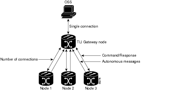
The GNE Session is the connection that multiplexes TL1 messages between the OSS/craftsperson and the GNE. The GNE demulitplexes incoming operations support system (OSS) TL1 commands and forwards them to the remote ENE. The GNE also multiplexes incoming responses and autonomous messages to the GNE Session. The ENE Session is the connection that exchanges messages between the GNE and the remote ENE. Figure 2-1 shows the GNE topology.
Figure 2-1 Example of a GNE topology
Each GNE can support six (5+1) concurrent gateway communication sessions (connections from an OS to the GNE). Five of these sessions are via the LAN (wire-wrap, active TCC/XTC LAN port, or DCC) and the sixth session is reserved for the active TCC/XTC serial port.
On each gateway communication session a GNE can establish TL1 sessions to up to 31 additional DCC- connected nodes, for a total DCC of 32 nodes. Each GNE can handle 32 nodes and 6 concurrent communication gateway sessions, and the GNE can handle up to a maximum of 96 ENEs/GNE. You can dynamically distribute the ENEs to balance the number of concurrent gateway communication sessions versus the number of NEs on the DCC. The GNE treats the 6 (5+1) concurrent gateway communication sessions and 96 ENEs/GNE limit as a resource pool ( Table 2-1) and continues to allocate resources until the pool is exhausted (see Table 2-2 for allocation examples). When the pool is exhausted the GNE returns an "All Gateways in Use" message or an "All ENE Connections in Use" message.
Table 2-1 Gateway Resource Pool
ENE sessions/GNE session1
6 (5+1)
96 (dynamically allocated)
31
Note
Issuing commands to specific nodes in the network is accomplished by entering a unique node name in the TID field in each TL1 message. The TID field is synonymous with the name of the node and is the second token in a TL1 command.
2.2 Implementing TL1 Gateway
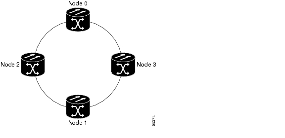
The following procedures demonstrate TL1 Gateway on a four-node ring (without TL1 Gateway in Figure 2-2 and with TL1 Gateway in Figure 2-3), where:
Node 0 is the GNE.
Node 1 is the ENE 1.
Node 2 is the INE 2.
Node 3 is the ENE 3.Figure 2-2 Four-node ring without TL1 Gateway
Figure 2-3 Four-node ring with TL1 Gateway
Log Into a Remote ENE
Step 1
Step 2
ACT-USER:NODE1:USERNAME:1234:PASSWORD;
The GNE forwards the login to ENE 1. After successful login, ENE 1 sends a COMPLD response.
Step 3
ACT-USER:NODE3:USERNAME:1234:PASSWORD;
The GNE forwards the login to ENE 3. After successful login, the ENE 3 sends a COMPLD response.
Forward Commands by Specifying the ENE TID (Node 1 or Node 3)
When you are logged into ENE 1 and ENE 3, enter a command and designate a specific TID, as shown in the following example:
RTRV-HDR:NODE1::1; will retrieve the header of Node 1 and
RTRV-HDR:NODE3::3; will retrieve the header of Node 3.
Receive Autonomous Messages from the Remote ENE
To receive autonomous messages from the remote ENE, you must log into the remote ENE. When you are logged in, you will start receiving autonomous messages. The source of the message is identified by the node TID as part of the message.
Log Out of a Remote ENE
To disconnect from a remote ENE, you must use the CANC-USER command as follows:
CANC-USER:NODE1:USERNAME:1; will disconnect ENE 1 and
CANC-USER:NODE3:USERNAME:3; will disconnect ENE 3.
The GNE forwards the logout to the remote ENEs. The GNE/ENE TCP session is closed.
![]()
![]()
![]()
![]()
![]()
![]()
![]()
![]()
Posted: Fri Feb 22 15:07:59 PST 2008
All contents are Copyright © 1992--2008 Cisco Systems, Inc. All rights reserved.
Important Notices and Privacy Statement.