cc/td/doc/product/ong/15400/r33docs
hometocprevnextglossaryfeedbacksearchhelp
PDF

Table Of Contents

Replace Hardware

3.1 Switch Traffic and Replace an In-Service Cross-Connect Card

3.2 Reset the TCC+ With a Card Pull

3.3 Replace the Air Filter

3.3.1 Inspect, Clean, and Replace the Reusable Air Filter

3.3.2 Inspect and Replace the Disposable Air Filter

3.4 Determine Replacement Hardware Compatibility

3.5 Replace the Fan-Tray Assembly

3.6 Replace the Alarm Interface Panel

3.7 Replace the Electrical Interface Assembly


Replace Hardware


This chapter provides procedures for replacing Cisco ONS 15454 hardware.

Every section is a procedure.

1. Switch Traffic and Replace an In-Service Cross-Connect Card—Complete this procedure to replace and in-service cross-connect card.

2. Reset the TCC+ With a Card Pull—Complete this procedure as needed to reset the TCC+ by performing a card pull.

3. Replace the Air Filter—Complete this procedure to replace a reusable or disposable air filter.

4. Determine Replacement Hardware Compatibility—Complete this procedure to verify replacement hardware compatibility.

5. Replace the Fan-Tray Assembly—Complete this procedure to replace the fan-tray assembly.

6. Replace the Alarm Interface Panel—Complete this procedure to replace the alarm interface panel (AIP).

7. Replace the Electrical Interface Assembly—Complete this procedure to replace the electrical interface assembly (EIA).

3.1 Switch Traffic and Replace an In-Service Cross-Connect Card

Purpose

This procedure replaces an in-service cross-connect card.

Tools/Equipment

Replacement cross-connect card

Prerequisite Procedures

None

Required/As Needed

As needed

Onsite/Remote

Onsite


Warning Do not reach into a vacant slot or chassis while you install or remove a module or a fan. Exposed circuitry could constitute an energy hazard.


Caution Removing any active card from the ONS 15454 can result in traffic interruption. Use caution when replacing cards and verify that only inactive or standby cards are being replaced. If the active card needs to be replaced, follow the steps below to switch the XC/XCVT/XC10G card to standby prior to removing the card from the node.


Note An improper removal (IMPROPRMVL) alarm is raised whenever a card pull is performed, unless the card is deleted in CTC first. The alarm will clear after the card replacement is complete.


Note In a UPSR, pulling the active XC/XCVT/XC10G without a lockout will cause UPSR circuits to switch.


Step 1 Log into the node where you will perform the XC/XCVT/XC10G card replacement:

a. From your PC, start Netscape or Internet Explorer.

b. In the Netscape or Internet Explorer Web address (URL) field, enter the ONS 15454 IP address. For initial setup, this is the default address, 192.1.0.2. Press Enter.


Note If you are logging into ONS 15454 nodes running different releases of CTC software, log into the node running the most recent release. If you log into a node with an older release, you receive an INCOMPATIBLE-SW alarm and the IP address of the login node will display instead of the node name. To check the software version of a node, select About CTC from the CTC Help menu.


A Java Console window displays the CTC file download status. The web browser displays information about your Java and system environments.

c. In the Login dialog box, type your name and password (both are case sensitive).

d. Each time you log into an ONS 15454, you can make selections on the following login options:

Node Name—Displays the IP address entered in the web browser and a pull-down menu of previously-entered ONS 15454 IP addresses. You can select any ONS 15454 on the list for the login, or you can enter the IP address (or node name) of any new node where you want to log in.

Additional Nodes—Displays a list of login node groups that were created. To create a login node group or add additional groups, see the Cisco ONS 15454 Procedure Guide.)


Note Topology hosts that were created in previous ONS 15454 releases by modifying the ctc.ini file are displayed as a "Topology Host" group under Additional Nodes.


Exclude Dynamically Discovered Nodes—Check this box to view only the ONS 15454 (and login node group members, if any) entered in the Node Name field. Nodes linked to the Node Name ONS 15454 through the DCC are not displayed. Using this option can decrease the CTC startup time in networks with many DCC-connected nodes.

e. Click Login.

Step 2 Ensure the working span is active on both local and remote nodes:

a. In node view, click the Maintenance > Ring tabs.

b. Locate the applicable span.

c. In the West Line and East Line columns, the working/active span is identified by (Work/Act).

Step 3 Ensure the working span is carrying error-free traffic (no SD or SF alarms present). Display the network view and click the Alarms tab to display alarms.

Step 4 Lockout the protection span according to the specific protection scheme:

a. Lockout the protection span in a BLSR protection scheme:

In node (default) view, click the Maintenance > Ring tabs.

Locate the applicable span.

In the West Line and East Line columns, the working/active span is identified by (Work/Act). Place a lockout on the East and West cards of the nodes adjacent to the XC switch node; for example, to switch the XC on Node B, place a lockout on the West card of Node A and on the East card of Node C, no lockout is necessary on Node B. Before the lockout is set, verify that the BLSR is not switched. If a lockout is set while the BLSR is switched, traffic can be lost.

<------East [Node A] West------East [Node B] West------East [Node C] West------>

b. Lockout the protection span in a 1+1 protection scheme:

In node (default) view, click the Maintenance > Protection tabs.

Choose the affected 1+1 protection group from the Protection Groups window.

In the Selected Group window, the working and protect spans appear. Choose the protect/standby card and choose Lockout from the inhibit switching row.

Click Yes on the confirmation dialog box.


Note An XC/XCVT/XC10G reset can cause a linear 1+1 OC-N protection switch or a BLSR protection switch.


c. Lockout the protection span in a UPSR protection scheme:

In network view, right-click the span where you want to switch UPSR traffic. Choose Circuits from the shortcut menu.

On the Circuits on Span dialog box, choose FORCE.


Caution The FORCE command overrides normal protective switching mechanisms. Applying this command incorrectly can cause traffic outages.

Step 5 When the protection span has been locked out, determine the active XC/XCVT/XC10G card. The ACT/STBY LED of the active card is green. The ACT/STBY LED of the standby card is amber.


Note You can also place the cursor over the card graphic to display a pop-up identifying the card as active or standby.


Step 6 Switch the active XC/XCVT/XC10G card to standby:

a. In the node view, click the Maintenance > XC Cards tabs.

b. Under Cross Connect Cards, choose Switch.

c. Click Yes on the Confirm Switch dialog box.


Note After the active XC/XCVT/XC10G goes into standby, the original standby slot becomes active. This causes the ACT/STBY LED to become green on the former standby card.


Step 7 Physically remove the new standby XC/XCVT/XC10G card from the ONS 15454.

Step 8 Insert the replacement XC/XCVT/XC10G card into the empty slot.

The replacement card boots up and becomes ready for service after approximately one minute.

Step 9 Release the protection lockout(s) applied in Step 4:

a. Log into the node where you will clear the Lock Out.

b. Click the Maintenance > Protection tabs.

c. Under Protection Groups, click the protection group that contains the card you want to clear.

d. Under Selected Group, click the card you want to clear.

e. From Inhibit Switching, click Unlock.

f. Click Yes on the confirmation dialog box.

The lock out is cleared.


3.2 Reset the TCC+ With a Card Pull

Purpose

Use this procedure to reseat a TCC+ card.

Tools/Equipment

None

Prerequisite Procedures

None

Required/As Needed

As needed

Onsite/Remote

Onsite


Note To determine whether you have an active or standby TCC+, position the cursor over the TCC+ card graphic to display the status.


Step 1 Ensure that the TCC+ you want to reset is in standby mode. On the TCC+ card, the ACT/STBY (Active/Standby) LED is amber when the TCC+ is in standby mode.

Step 2 When the TCC+ is in standby mode, unlatch both the top and bottom ejector levers on the TCC+ card.

Step 3 Physically pull the card at least partly out of the slot until the lighted LEDs turn off.

Step 4 Wait 30 seconds. Reinsert the card and close the ejector levers.


Note The TCC+ will take several minutes to reboot and will display the amber standby LED after rebooting. Refer to the Cisco ONS 15454 Procedure Guide for more information about LED behavior during TCC+ reboots.


3.3 Replace the Air Filter

Purpose

The following procedure describes how to replace reusable and disposable air filters.

Tools/Equipment

Spare air filters

Prerequisite Procedures

None

Required/As Needed

As needed

Onsite/Remote

Onsite


Warning Do not reach into a vacant slot or chassis while you install or remove a module or a fan. Exposed circuitry could constitute an energy hazard.


Note Although the filter will work if it is installed with either side facing up, Cisco recommends that you install it with the metal bracing facing up to preserve the surface of the filter.


Step 1 To replace the reusable air filter, complete the "3.3.1Inspect, Clean, and Replace the Reusable Air Filter" task.

Step 2 To replace the disposable air filter, complete the "3.3.2Inspect and Replace the Disposable Air Filter" task.


3.3.1 Inspect, Clean, and Replace the Reusable Air Filter

Purpose

This task ensures that the air filter is free from dirt and dust, which allows optimum air flow and prevents dirt and dust from entering the shelf.

Tools/Equipment

Vacuum or detergent and water faucet, spare filter, pinned hex key

Prerequisite Procedures

None

Required/As Needed

Inspection required every 30 days. Clean as needed.

Onsite/Remote

Onsite


Step 1 Verify that you are replacing a reusable air filter. The reusable filter is made of a gray, open-cell, polyurethane foam that is specially coated to provide fire and fungi resistance. NEBS 3E and later versions of the ONS 15454 use a reusable air filter.

Step 2 If the air filter is installed in the external filter brackets, slide the filter out of the brackets while being careful not to dislodge any dust that may have collected on the filter and proceed to Step 5. Figure 3-1 illustrates a reusable fan-tray air filter in an external filter bracket. If the filter is installed beneath the fan tray and not in the external filter brackets:

Step 3 Open the front door of the shelf assembly.

a. Open the front door lock.

The ONS 15454 comes with a pinned hex key for locking and unlocking the front door. Turn the key counterclockwise to unlock the door and clockwise to lock it.

b. Press the door button to release the latch.

c. Swing the door open.

Step 4 Remove the front door (optional). If you do not want to remove the door, proceed to Step 5:

a. Detach the ground strap from either the door or the chassis by removing one of the Kepnuts.

b. Place the Kepnut back on the stud after the ground strap is removed to avoid misplacement.

c. Secure the dangling end of the ground strap to the door or chassis with tape.

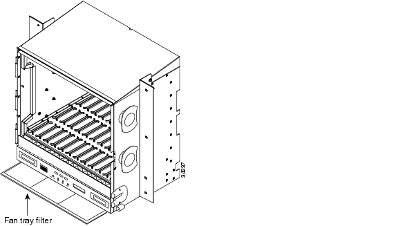
Figure 3-1 A reusable fan-tray air filter in an external filter bracket (front door removed)

Step 5 Push the outer side of the handles on the fan-tray assembly to expose the handles.

Step 6 Pull the handles and slide the fan-tray assembly one inch out of the shelf assembly and wait until the fans stop.

Step 7 When the fans have stopped, pull the fan-tray assembly completely out of the shelf assembly.

Step 8 Gently remove the air filter from the shelf assembly. Be careful not to dislodge any dust that may have collected on the filter.

Step 9 Visually inspect the air filter material for dirt and dust.

Step 10 If the reusable air filter contains a concentration of dirt and dust, either vacuum or wash the air filter. Prior to washing the air filter, replace the dirty air filter with a clean air filter (spare filters should be kept in stock) and also replace the fan-tray assembly. Wash the dirty air filter under a faucet with a light detergent.


Note Cleaning should take place outside the operating environment to avoid releasing dirt and dust near the equipment.


Step 11 If you washed the filter, allow it to completely air dry for at least eight hours.


Warning Do not put a damp filter back in the ONS 15454.

a. If the air filter is installed in the external filter brackets, slide the air filter all the way to the back of the brackets to complete the procedure.

b. If the filter is installed beneath the fan-tray assembly, remove the fan-tray assembly, and slide the air filter into the recessed compartment at the bottom of the shelf assembly. Put the front edge of the air filter flush against the front edge of the recessed compartment. Push the fan tray back into the shelf assembly.


Caution If the fan tray does not slide all the way to the back of the shelf assembly, pull the fan tray out and readjust the position of the reusable filter until the fan tray fits correctly.

Note On a powered-up ONS 15454, the fans start immediately after the fan-tray assembly is correctly inserted.


Step 12 To verify that the tray is plugged into the backplane, ensure that the LCD on the front of the fan-tray assembly is activated and displays node information.

Step 13 Rotate the retractable handles back into their compartments.

Step 14 If you replace the door, also reattach the ground strap.

Step 15 Close and lock the door.


3.3.2 Inspect and Replace the Disposable Air Filter

Purpose

This task ensures that the air filter is free from dirt and dust to allow optimum air flow and prevent dirt and dust from entering the ONS 15454.

Tools/Equipment

Extra filters, pinned hex key

Prerequisite Procedures

None

Required/As Needed

Inspection required every 30 days. Replace as needed.

Onsite/Remote

Onsite


Note The disposable air filter is installed beneath the fan-tray assembly only, so you must remove the fan-tray assembly to inspect and replace the disposable air filter.


Step 1 Verify that you are replacing a disposable air filter. The disposable filter is made of spun white polyester that is flame retardant. NEBS 3E and earlier versions of the ONS 15454 use a disposable air filter.

Step 2 Open the front door of the shelf assembly.

a. Open the front door lock.

The ONS 15454 comes with a pinned hex key for locking and unlocking the front door. Turn the key counterclockwise to unlock the door and clockwise to lock it.

b. Press the door button to release the latch.

c. Swing the door open.

Step 3 Remove the front door (optional). If you do not want to remove the door, proceed to Step 4:

a. Detach the ground strap from either the door or the chassis by removing one of the Kepnuts.

b. Place the Kepnut back on the stud after the ground strap is removed to avoid misplacement.

c. Secure the dangling end of the ground strap to the door or chassis with tape.

Step 4 Push the outer side of the handles on the fan-tray assembly to expose the handles.

Step 5 Pull the handles and slide the fan-tray assembly one inch out of the shelf assembly and wait until the fans stop.

Step 6 When the fans have stopped, pull the fan-tray assembly completely out of the shelf assembly ( Figure 3-2).

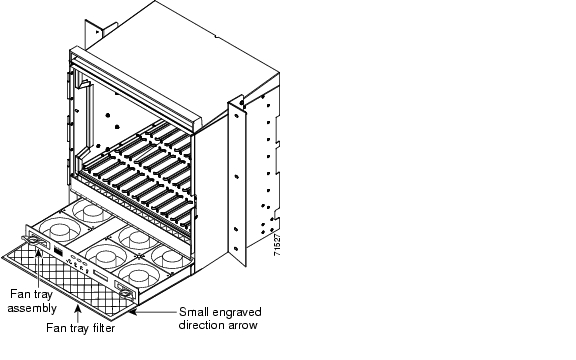
Figure 3-2 Inserting or removing the fan-tray assembly (front door removed)

Step 7 Gently remove the air filter from the shelf assembly ( Figure 3-3). Be careful not to dislodge any dust that may have collected on the filter.

Step 8 Visually inspect the white filter material for dirt and dust.

Step 9 If the air filter shows a heavy concentration of dirt and dust, replace it with a new filter by sliding the filter into the bottom of the shelf assembly. Make sure that the front of the filter is flush with the front of the shelf assembly and that the air flow indicators on the filter point upwards.

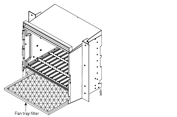
Figure 3-3 Inserting or removing a disposable fan-tray air filter (front door removed)

Step 10 Slide the fan-tray assembly into the shelf assembly until the electrical plug at the rear of the tray plugs into the corresponding receptacle on the backplane.

Step 11 To verify that the tray is plugged into the backplane, ensure that the LCD on the front of the fan-tray assembly is activated and displays node information.

Step 12 Rotate the retractable handles back into their compartments.

Step 13 If you replace the door, also reattach the group strap.

Step 14 Close and lock the door.


3.4 Determine Replacement Hardware Compatibility

Purpose

This procedure determines replacement hardware compatibility.

Tools/Equipment

None

Prerequisite Procedures

None

Required/As Needed

Required when replacing the fan-tray assembly and alarm interface panel.

Onsite/Remote

Both


Caution The 15454-FTA3 fan-tray assembly can only be installed in ONS 15454 Release 3.1 and later shelf assemblies (15454-SA-ANSI, P/N: 800-19857). It includes a pin that does not allow it to be installed in ONS 15454 shelf assemblies released before ONS 15454 Release 3.1 (15454-SA-NEBS3E, 15454-SA-NEBS3, and 15454-SA-R1, P/N: 800-07149). Equipment damage can result from attempting to install the 15454-FTA3 in a non-compatible shelf assembly.


Note The 15454-SA-ANSI shelf assembly and 15454-FTA3 fan-tray assembly are required with the ONS 15454 XC10G, OC-192, and OC-48AS cards.


Note The 5A alarm interface panel (AIP) (73-7665-XX) is required when installing the 15454-FTA3 fan-tray assembly.


Step 1 Review Table 3-1 to ensure you have compatible components when replacing the fan-tray assembly or the AIP and note the alarms that will occur when an incompatible combination of hardware is installed.


Note If you need to determine the hardware that has been installed on a node, click the inventory tab in node view.


Table 3-1 Incompatibility Alarms

Shelf Assembly 1
Fan Tray2
AIP3
10G Cards4
Ethernet Cards5
Alarms

No fuse

MEA on AIP

NEBS3E or NEBS3

2A

2A

No

None

NEBS3E or NEBS3

2A

2A

Yes

MEA on 10G

NEBS3E or NEBS3

2A

5A

No

None

NEBS3E or NEBS3

2A

5A

Yes

MEA on 10G

NEBS3E or NEBS3

5A

2A

No

MEA on fan tray

NEBS3E or NEBS3

5A

2A

Yes

MEA on fan tray and 10G cards

NEBS3E or NEBS3

5A

5A

No

None

NEBS3E or NEBS3

5A

5A

Yes

MEA on 10G

ANSI

2A

2A

No

None

ANSI

2A

2A

Yes

2.5G compatible

MEA on fan tray, AIP, Ethernet

ANSI

2A

2A

Yes

10G compatible

MEA on fan tray, AIP

ANSI

2A

5A

No

Either

None

ANSI

2A

5A

Yes

2.5G compatible

MEA on fan tray, Ethernet

ANSI

2A

5A

Yes

10G compatible

MEA on fan tray

ANSI

5A

2A

No

Either

MEA on AIP

ANSI

5A

2A

Yes

2.5G compatible

MEA on AIP, Ethernet

ANSI

5A

2A

Yes

10G compatible

MEA on AIP

ANSI

5A

5A

No

Either

None

ANSI

5A

5A

Yes

Either

None

1 15454-SA-ANSI (P/N: 800-19857-01) = ONS 15454 Release 3.1 and later shelf assembly,
15454-SA-NEBS3E (P/N: 800-07149-xx) or 15454-SA-NEBS3 (P/N: 800-06741-xx) = shelf assemblies released before ONS 15454 Release 3.1

2 5A Fan Tray = 15454-FTA3 (P/N: 800-19858-xx) or 15454-FTA3-T (P/N: 800-21448-xx),
2A Fan Tray = 15454-FTA2 (P/Ns: 800-07145-xx, 800-07385-xx, 800-19591-xx, 800-19590-xx)

3 5A AIP (P/N: 73-7665-01), 2A AIP (P/N: 73-5262-01)

4 10G cards = XC-10G, OC-192, OC-48AS

5 2.5G compatible Ethernet cards = E1000-T, E1000-2, E1000T-G, E10002-G, G1000-4
10G compatible Ethernet cards = E1000T-G, E10002-G, G1000-4


Step 2 See the "Replace the Fan-Tray Assembly" section to replace the fan-tray assembly or the "Inspect and Replace the Disposable Air Filter" section to replace the alarm interface panel.


3.5 Replace the Fan-Tray Assembly

To replace the fan-tray assembly (FTA), it is not necessary to move any of the cable management facilities. You can remove the fan-tray assembly using the retractable handles and replace it by pushing until it plugs into the receptacle on the back panel.

Purpose

This procedure replaces an existing FTA with a new FTA.

Tools/Equipment

None

Prerequisite Procedures

Determine Replacement Hardware Compatibility

Required/As Needed

As needed

Onsite/Remote

Onsite


Caution The 15454-FTA3 fan-tray assembly can only be installed in ONS 15454 Release 3.1 and later shelf assemblies (15454-SA-ANSI, P/N: 800-19857). It includes a pin that does not allow it to be installed in ONS 15454 shelf assemblies released before ONS 15454 Release 3.1 (15454-SA-NEBS3E, 15454-SA-NEBS3, and 15454-SA-R1, P/N: 800-07149). Equipment damage can result from attempting to install the 15454-FTA3 in a non-compatible shelf assembly.


Caution Do not force a fan-tray assembly into place. Doing so can damage the connectors on the fan tray and/or the connectors on the back panel of the shelf assembly.


Note The 15454-SA-ANSI shelf assembly and 15454-FTA3 fan-tray assembly are required with the ONS 15454 XC-10G, OC-192, and OC-48 any slot (AS) cards.


Step 1 Open the front door of the shelf assembly:

a. Open the front door lock.

The ONS 15454 comes with a pinned hex key for locking and unlocking the front door. Turn the key counterclockwise to unlock the door and clockwise to lock it.

b. Press the door button to release the latch.

c. Swing the door open.

Step 2 Remove the front door (optional). If you do not want to remove the door, proceed to Step 3:

a. Detach the ground strap from either the door or the chassis by removing one of the Kepnuts.

b. Place the Kepnut back on the stud after the ground strap is removed to avoid misplacement.

c. Secure the dangling end of the ground strap to the door or chassis with tape.

Step 3 Push the outer side of the handles on the fan-tray assembly to expose the handles.

Step 4 Fold out the retractable handles at the outside edges of the fan tray.

Step 5 Pull the handles and slide the fan-tray assembly one inch out of the shelf assembly and wait until the fans stop.

Step 6 When the fans have stopped, pull the fan-tray assembly completely out of the shelf assembly. Figure 3-4 shows the location of the fan tray.

Step 7 If you are replacing the fan-tray air filter and it is installed beneath the fan-tray assembly, slide the existing air filter out of the shelf assembly and replace it before replacing the fan-tray assembly.

If you are replacing the fan-tray air filter and it is installed in the external bottom bracket, you can slide the existing air filter out of the bracket and replace it at anytime. For more information on the fan-tray air filter, see the "Replace the Air Filter" section.

Step 8 Slide the new fan tray into the shelf assembly until the electrical plug at the rear of the tray plugs into the corresponding receptacle on the backplane.

Step 9 To verify that the tray has plugged into the backplane, check that the LCD on the front of the fan tray is activated.

Step 10 If you replace the door, also reattach the ground strap.

Step 11 Close and lock the door.

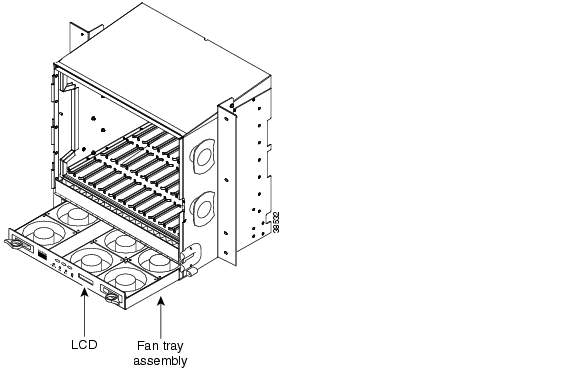
Figure 3-4 Removing or replacing the fan-tray assembly (front door removed)


3.6 Replace the Alarm Interface Panel

Purpose

This procedure replaces an existing AIP with a new AIP on an in-service system without affecting traffic

Tools/Equipment

#2 phillips screw driver

Prerequisite Procedures

Determine Replacement Hardware Compatibility

Required/As Needed

As needed

Onsite/Remote

Onsite


Caution Do not use a 2A AIP with a 5A fan-tray assembly; doing so will cause a blown fuse on the AIP.


Caution There is a risk of Ethernet traffic disruptions. Contact the Cisco Technical Assistance Center (TAC) at 877-323-7368 when prompted to do so in the procedure.


Caution Always use the supplied ESD wristband when working with a powered ONS 15454. Plug the wristband cable into the ESD jack located on the lower-right outside edge of the shelf assembly.


Note Perform this procedure in a maintenance window. Resetting the active TCC+ can cause a service disruption of less then 50 ms to OC-N or DS-N traffic. Resetting the active TCC+ will cause a service disruption of 3-5 minutes on all Ethernet traffic due to Spanning Tree Reconvergence.


Step 1 Ensure that all nodes in the affected network are running the same software version before replacing the AIP and repairing circuits:

a. Log into CTC. See Step 1 in the "Switch Traffic and Replace an In-Service Cross-Connect Card" procedure for instructions.

b. In network view, click the Maintenance > Software tabs. The working software version for each node is listed in the Working Version column.

c. If you need to upgrade the software on a node, refer to the Cisco ONS 15454 Software Upgrade Guide for software upgrade procedures. No hardware should be changed or circuit repair performed until after the software upgrade is complete. If you do not need to upgrade software or have completed the software upgrade, proceed to Step 2.

Step 2 Record the MAC address of the old AIP:

a. Log into the node where you will replace the AIP. For login procedures, see the Cisco ONS 15454 Procedure Guide.

b. In node view, click on the Provisioning > Network tabs.

c. Record the MAC address shown in the General tab in Figure 3-5.

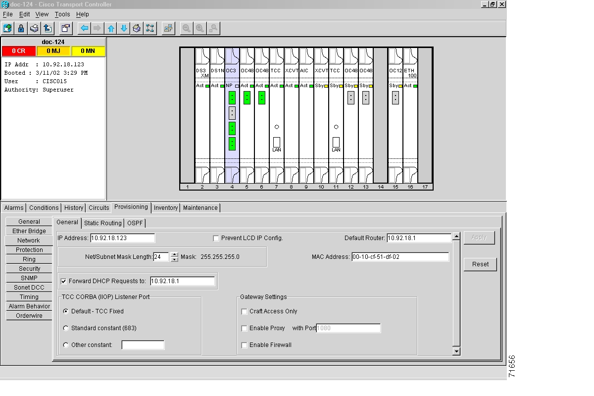
Figure 3-5 Find the MAC address

Step 3 Call Cisco TAC at 877-323-7368 for assistance in replacing the AIP and maintaining the original MAC address.

Step 4 Unscrew the five screws that hold the lower backplane cover in place ( Figure 3-6).

Step 5 Grip the lower backplane cover and gently pull away from the backplane.

Figure 3-6 Lower backplane cover

Step 6 Unscrew the two screws that hold the AIP cover in place.

Step 7 Grip the cover and gently pull away from the backplane.


Note On the 15454-SA-NEBS3E, 15454-SA-NEBS3, and 15454-SA-R1 (P/N: 800-07149) shelves the AIP cover is clear plastic. On the 15454-SA-ANSI shelf (P/N: 800-19857), the AIP cover is metal.


Step 8 Grip the AIP and gently pull away from the backplane.

Step 9 Disconnect the fan-tray assembly power cable from the AIP.

Step 10 Set the old AIP aside for return to Cisco.


Caution The type of shelf the AIP resides in will determine the version of AIP that will replace the failed AIP. The 15454-SA-ANSI shelf (P/N: 800-19857) currently uses the 5A AIP, (P/N: 73-7665-01). The 15454-SA-NEBS3E, 15454-SA-NEBS3, and 15454-SA-R1 (P/N: 800-07149) shelves and lower currently use the 2A AIP (P/N: 73-5262-01).

Caution Do not put a 2A AIP (P/N: 73-5262-01) into a 15454-SA-ANSI shelf (P/N: 800-19857); doing so will cause a blown fuse on the AIP.

Step 11 Attach the fan-tray assembly power cable to the new AIP.

Step 12 Place the new AIP on the backplane by plugging the panel into the backplane using the DIN connector.

Step 13 Replace the AIP cover over the AIP and secure the cover with the two screws.

Step 14 Replace the lower backplane cover and secure the cover with the five screws.

Step 15 In node view, click on the Provisioning > Network tabs.


Caution Cisco recommends TCC+ resets be performed in a maintenance window to avoid any potential service disruptions.

Step 16 Reset the standby TCC+:

a. In node view, right click on the standby TCC+ card and choose Reset Card.

b. Click Yes on the Resetting Card dialog box. As the card resets, a loading (Ldg) indication will appear on the card in CTC.


Note The reset will take approximately five minutes. Do not perform any other steps until the reset is complete.


Step 17 Reset the active TCC+:

a. In node view, right click on the active TCC+ card and choose Reset Card.

b. Click Yes on the Resetting Card dialog box. As the card resets, a Ldg indication will appear on the card in CTC.


Note The reset will take approximately five minutes and CTC will lose its session with the node.


Step 18 Click File from the menu bar and choose Exit to exit the CTC session.

Step 19 Login back into the node. At the Login dialog box, choose (None) from the Additional Nodes pull-down menu.

Step 20 Record the new MAC address:

a. In node view, click on the Provisioning > Network tabs.

b. Record the MAC address shown in the General tab.

Step 21 In node view, click on the Circuits tab. Note that all circuits listed are in an INCOMPLETE state.

Step 22 In node view, choose Tools from the menu bar and click Repair Circuits ( Figure 3-7). The Circuit Repair dialog box is displayed.

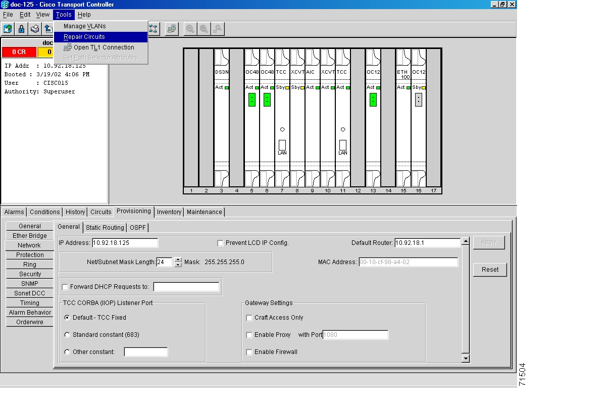
Figure 3-7 Repair Circuits in the Menu Bar

Step 23 Read the instructions in the Circuit Repair dialog box ( Figure 3-8). If all the steps in the dialog box have been completed, click Next>. Ensure you have the old and new MAC addresses.

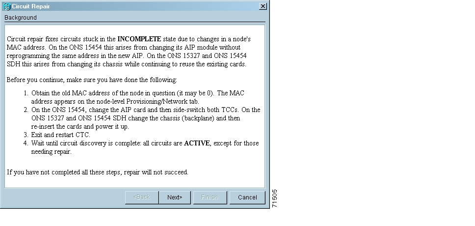
Figure 3-8 Repairing circuits

Step 24 The Node MAC Addresses dialog box displays ( Figure 3-9):

a. From the Node pull down menu, choose the name of the node where you replaced the AIP.

b. In the Old MAC Address field, enter the old MAC address that was recorded in Step 2.

c. Click Next.

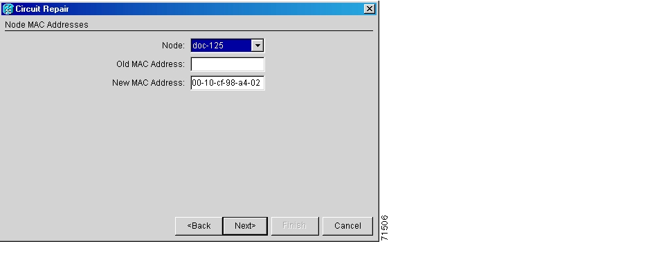
Figure 3-9 Recording the old MAC address before replacing the AIP

Step 25 The Repair Circuits dialog box displays ( Figure 3-10). Read the information in the dialog box and click Finish.

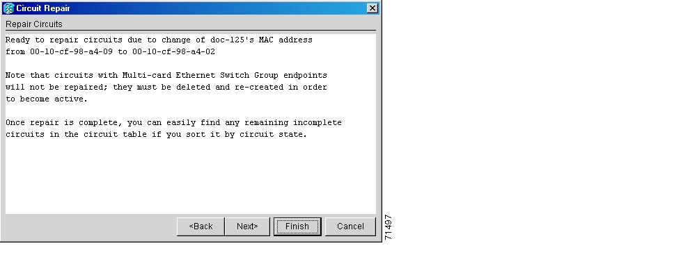
Figure 3-10 Circuit repair information


Note The CTC session will freeze until all circuits are repaired. Circuit repair can take up to five minutes or more depending on the number of circuits provisioned.


Step 26 When the circuit repair is complete, the Circuits Repaired dialog box will display.

Step 27 Click OK.

Step 28 In the new node view, click on the Circuits tab. Note that all circuits listed are in an ACTIVE state. If all circuits listed are not in an ACTIVE state, call Cisco TAC at 877-323-7368 for assistance.

Step 29 Return the defective AIP. You must follow the standard Return Material Authorizations (RMA) procedures; call (800) 553-NETS (6387) if you do not have an RMA number.


3.7 Replace the Electrical Interface Assembly

Purpose

This procedure replaces an existing EIA with a new EIA.

Tools/Equipment

#2 phillips screw driver

BNC insertion and removal tool (Optional; for use with high-density BNC EIAs)

Prerequisite Procedures

None

Required/As Needed

As needed

Onsite/Remote

Onsite


Step 1 To remove the lower backplane cover, loosen the five screws that secure it to the ONS 15454 and pull it away from the shelf assembly ( Figure 3-6).

Step 2 Loosen the nine perimeter screws that hold the backplane sheet metal cover or EIA in place. Do not remove the interior screws.


Note If you are removing an AMP Champ EIA, remove the fastening plate before proceeding. To remove the fastening plate, loosen the two thumbscrews.


Step 3 If a backplane cover is attached to the ONS 15454, lift the panel by the bottom to remove it from the shelf assembly and store the panel for later use.

Step 4 If an EIA is attached to the ONS 15454, lift the EIA handles and gently pull the EIA panel away from the backplane.


Note Attach backplane sheet metal covers whenever EIAs are not installed.


Step 5 Line up the connectors on the new EIA with the mating connectors on the backplane.

Step 6 Gently push the EIA until both sets of connectors fit together snugly.

Step 7 Replace the nine perimeter screws that you removed while removing the backplane cover.

Step 8 If you are installing an AMP Champ EIA, attach the fastening plate with the two thumbscrews.

Step 9 Reattach the lower backplane cover.


hometocprevnextglossaryfeedbacksearchhelp

Posted: Fri Feb 22 12:59:14 PST 2008
All contents are Copyright © 1992--2008 Cisco Systems, Inc. All rights reserved.
Important Notices and Privacy Statement.