|
|

Table Of Contents
9.1 Bidirectional Line Switched Rings
9.1.6 Two-Fiber BLSR to Four-Fiber BLSR Upgrade
9.2 Unidirectional Path Switched Rings
9.5 Path-Protected Mesh Networks
SONET Topologies
This chapter explains Cisco ONS 15454 SONET topologies. To provision topologies, refer to the Cisco ONS 15454 Procedure Guide.
Chapter topics include:
•
Bidirectional Line Switched Rings
•
•
Table 9-1 shows the SONET rings that can be created on each ONS 15454 node.
Table 9-1 ONS 15454 Rings
All rings
5
BLSRs
2
2-Fiber BLSR
2
4-Fiber BLSR
1
UPSR
4
9.1 Bidirectional Line Switched Rings
The ONS 15454 can support two concurrent BLSRs in one of the following configurations:
•
•
Each BLSR can have up to 32 ONS 15454s. Because the working and protect bandwidths must be equal, you can create only OC-12 (two-fiber only), OC-48, or OC-192 BLSRs.
Note
9.1.1 Two-Fiber BLSRs
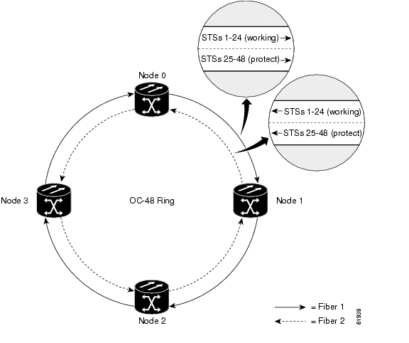
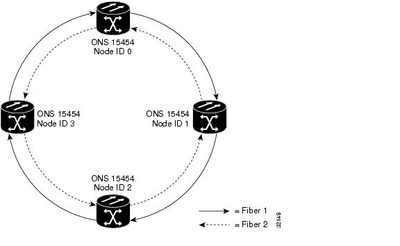
In two-fiber BLSRs, each fiber is divided into working and protect bandwidths. For example, in an OC-48 BLSR ( Figure 9-1), STSs 1 - 24 carry the working traffic, and STSs 25 - 48 are reserved for protection. Working traffic (STSs 1 - 24) travels in one direction on one fiber and in the opposite direction on the second fiber. The Cisco Transport Controller (CTC) circuit routing routines calculate the "shortest path" for circuits based on many factors, including requirements set by the circuit provisioner, traffic patterns, and distance. For example, in Figure 9-1, circuits going from Node 0 to Node 1 typically will travel on Fiber 1, unless that fiber is full, in which case circuits will be routed on Fiber 2 through Node 3 and Node 2. Traffic from Node 0 to Node 2 (or Node 1 to Node 3), may be routed on either fiber, depending on circuit provisioning requirements and traffic loads.
Figure 9-1 A four-node, two-fiber BLSR
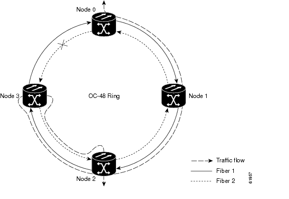
The SONET K1 and K2 bytes carry the information that governs BLSR protection switches. Each BLSR node monitors the K bytes to determine when to switch the SONET signal to an alternate physical path. The K bytes communicate failure conditions and actions taken between nodes in the ring.
If a break occurs on one fiber, working traffic targeted for a node beyond the break switches to the protect bandwidth on the second fiber. The traffic travels in reverse direction on the protect bandwidth until it reaches its destination node. At that point, traffic is switched back to the working bandwidth.
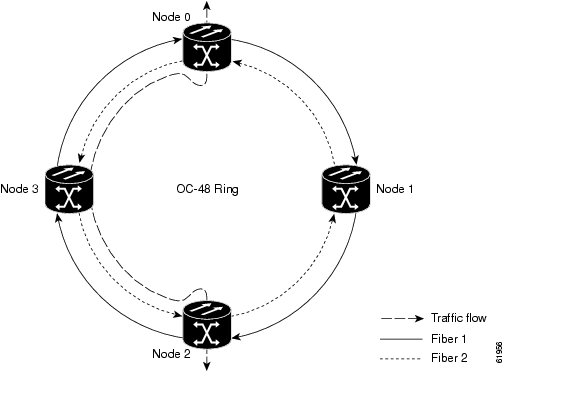
Figure 9-2 shows a sample traffic pattern on a four-node, two-fiber BLSR.
Figure 9-2 Four-node, two-fiber BLSR sample traffic pattern
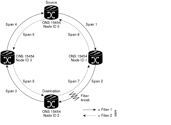
Figure 9-3 shows how traffic is rerouted following a line break between Node 0 and Node 3.
•
•
Figure 9-3 Four-node, two-fiber BLSR traffic pattern following line break
9.1.2 Four-Fiber BLSRs
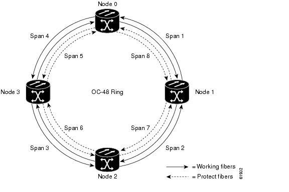
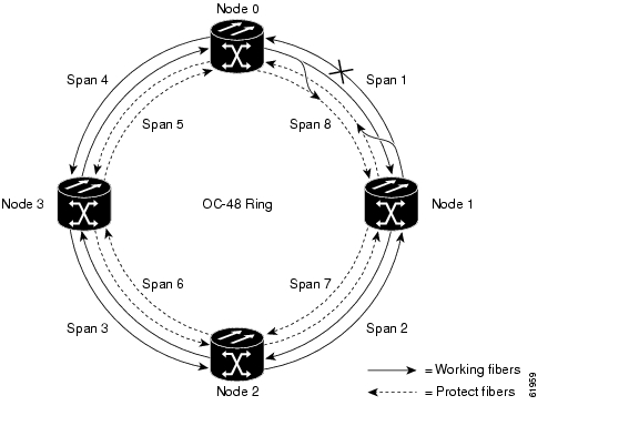
Four-fiber BLSRs double the bandwidth of two-fiber BLSRs. Because they allow span switching as well as ring switching, four-fiber BLSRs increase the reliability and flexibility of traffic protection. Two fibers are allocated for working traffic and two fibers for protection, as shown in Figure 9-4. To implement a four-fiber BLSR, you must install four OC-48 or OC-48AS cards, or four OC-192 cards at each BLSR node.
Figure 9-4 A four-node, four-fiber BLSR
Four-fiber BLSRs provide span and ring switching:
•
•
Figure 9-5 A four-fiber BLSR span switch
Figure 9-6 A four-fiber BLSR ring switch
9.1.3 BLSR Bandwidth
BLSR nodes can terminate traffic that is fed from either side of the ring. Therefore, BLSRs are suited for distributed node-to-node traffic applications such as interoffice networks and access networks.
BLSRs allow bandwidth to be reused around the ring and can carry more traffic than a network with traffic flowing through one central hub. BLSRs can also carry more traffic than a UPSR operating at the same OC-N rate. Table 9-2 shows the bidirectional bandwidth capacities of two-fiber BLSRs. The capacity is the OC-N rate divided by two, multiplied by the number of nodes in the ring minus the number of pass-through STS-1 circuits. Table 9-3 shows the bidirectional bandwidth capacities of four-fiber BLSRs.
Table 9-2 Two-Fiber BLSR Capacity
OC-12
STS1-6
STS 7-12
OC-48
STS 1-24
STS 25-48
24 x N - PT
OC-192
STS 1-96
STS 97-192
96 x N - PT
1 N equals the number of ONS 15454 nodes configured as BLSR nodes.
2 PT equals the number of STS-1 circuits passed through ONS 15454 nodes in the ring (capacity can vary depending on the traffic pattern).
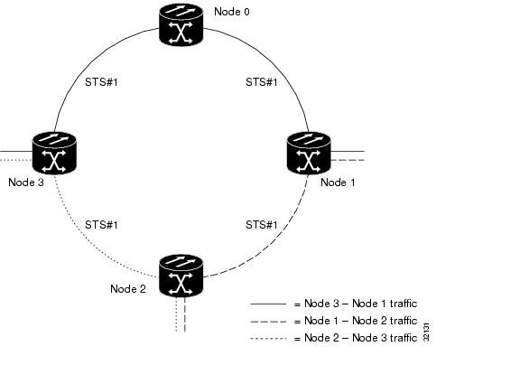
Figure 9-7 shows an example of BLSR bandwidth reuse. The same STS carries three different traffic sets simultaneously on different spans on the ring: one set from Node 3 to Node 1, one from Node 1 to Node 2, and another from Node 2 to Node 3.
Figure 9-7 BLSR bandwidth reuse
9.1.4 Sample BLSR Application
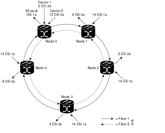
Figure 9-8 shows a sample two-fiber BLSR implementation. A regional long-distance network connects to other carriers at Node 0. Traffic is delivered to the service provider's major hubs.
•
•
•
Figure 9-8 A five-node BLSR
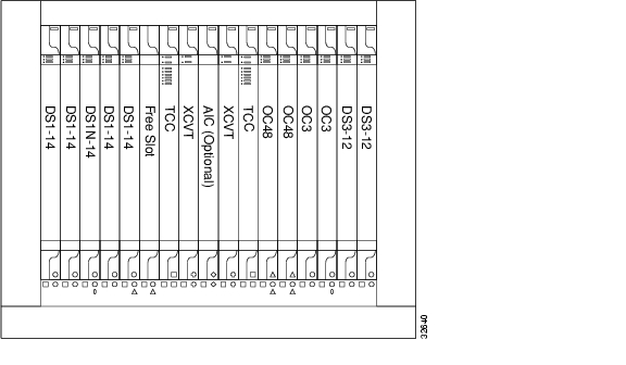
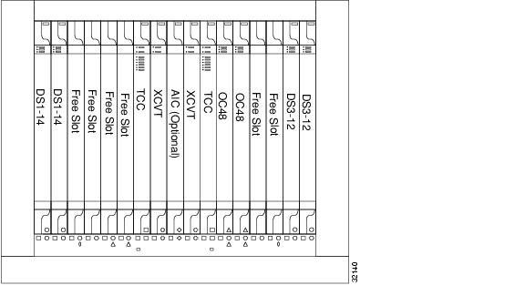
Figure 9-9 shows the shelf assembly layout for Node 0, which has one free slot. Figure 9-10 shows the shelf assembly layout for the remaining sites in the ring. In this BLSR configuration, an additional eight DS-3s at Node IDs 1 and 3 can be activated. An additional four DS-3s can be added at Node ID 4, and ten DS-3s can be added at Node ID 2. Each site has free slots for future traffic needs.
Figure 9-9 Shelf assembly layout for Node 0 in Figure 9-8
Figure 9-10 Shelf assembly layout for Nodes 1 - 4 in Figure 9-8
9.1.5 BLSR Fiber Connections
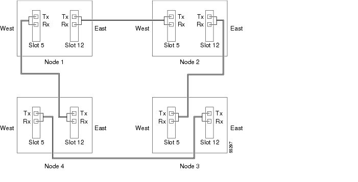
Plan your fiber connections and use the same plan for all BLSR nodes. For example, make the east port the farthest slot to the right and the west port the farthest left. Plug fiber connected to an east port at one node into the west port on an adjacent node. Figure 9-11 shows fiber connections for a two-fiber BLSR with trunk cards in Slot 5 (west) and Slot 12 (east).
Note
For four-fiber BLSRs, use the same east—west connection pattern for the working and protect fibers. Do not mix working and protect card connections. The BLSR will not function if working and protect cards are interconnected. Figure 9-12 shows fiber connections for a four-fiber BLSR. Slot 5 (west) and Slot 12 (east) carry the working traffic. Slot 6 (west) and Slot 13 (east) carry the protect traffic.
Figure 9-11 Connecting fiber to a four-node, two-fiber BLSR
Figure 9-12 Connecting fiber to a four-node, four-fiber BLSR
9.1.6 Two-Fiber BLSR to Four-Fiber BLSR Upgrade
Two-fiber OC-48 or OC-192 BLSRs can be upgraded to four-fiber BLSRs. To upgrade, you install two OC-48 or OC-192 cards at each two-fiber BLSR node, then log into CTC and upgrade each node from two-fiber to four-fiber. The fibers that were divided into working and protect bandwidths for the two-fiber BLSR are now fully allocated for working BLSR traffic.
9.2 Unidirectional Path Switched Rings
UPSRs provide duplicate fiber paths around the ring. Working traffic flows in one direction and protection traffic flows in the opposite direction. If a problem occurs in the working traffic path, the receiving node switches to the path coming from the opposite direction.
CTC automates ring configuration. UPSR traffic is defined within the ONS 15454 on a circuit-by-circuit basis. If a path-protected circuit is not defined within a 1+1 or BLSR line protection scheme and path protection is available and specified, CTC uses UPSR as the default.
Figure 9-13 shows a basic UPSR configuration. If Node ID 0 sends a signal to Node ID 2, the working signal travels on the working traffic path through Node ID 1. The same signal is also sent on the protect traffic path through Node ID 3. If a fiber break occurs ( Figure 9-14), Node ID 2 switches its active receiver to the protect signal coming through Node ID 3.
Because each traffic path is transported around the entire ring, UPSRs are best suited for networks where traffic concentrates at one or two locations and is not widely distributed. UPSR capacity is equal to its bit rate. Services can originate and terminate on the same UPSR, or they can be passed to an adjacent access or interoffice ring for transport to the service-terminating location.
Figure 9-13 A basic four-node UPSR
Figure 9-14 A UPSR with a fiber break
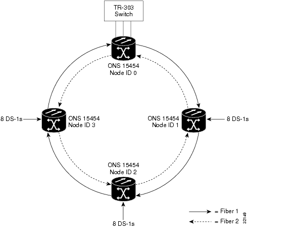
Figure 9-15 shows a common UPSR application. OC-3 optics provide remote switch connectivity to a host TR-303 switch. In the example, each remote switch requires eight DS-1s to return to the host switch. Figure 9-16 and Figure 9-17 show the shelf layout for each site.
Figure 9-15 An OC-3 UPSR
Node ID 0 has four DS1-14 cards to provide 56 active DS-1 ports. The other sites only require two DS1-14 cards to handle the eight DS-1s to and from the remote switch. You can use the other half of each ONS 15454 shelf assembly to provide support for a second or third ring to other existing or planned remote sites.
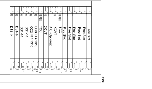
In this sample OC-3 UPSR, Node ID 0 contains four DS1-14 cards and two OC3 IR 4 1310 cards. Six free slots also exist in this setup and can be provisioned with cards or left empty. Figure 9-16 shows the shelf setup for these cards.
Figure 9-16 Layout of Node ID 0 in the OC-3 UPSR example (Figure 5-15)
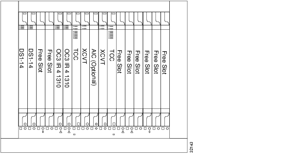
In the Figure 9-15 example, Nodes IDs 1 - 3 each contain two DS1-14 cards and two OC3 4 IR 1310 cards. Eight free slots exist. They can be provisioned with other cards or left empty. Figure 9-17 shows the shelf assembly setup for this configuration sample.
Figure 9-17 Layout of Node IDs 1 - 3 in the OC-3 UPSR example (Figure 5-15)
9.3 Subtending Rings
The ONS 15454 supports up to ten SONET DCCs. Therefore, one ONS 15454 node can terminate and groom any one of the following ring combinations:
•
•
•
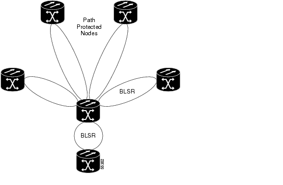
Subtending rings from an ONS 15454 reduces the number of nodes and cards required and reduces external shelf-to-shelf cabling. Figure 9-18 shows an ONS 15454 with multiple subtending rings.
Figure 9-18 An ONS 15454 with multiple subtending rings
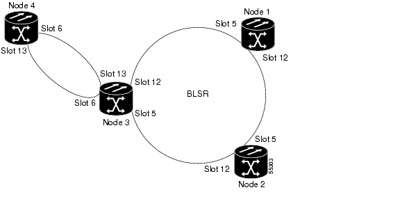
Figure 9-19 shows a UPSR subtending from a BLSR. In this example, Node 3 is the only node serving both the BLSR and UPSR. OC-N cards in Slots 5 and 12 serve the BLSR, and OC-N cards in Slots 6 and 13 serve the UPSR.
Figure 9-19 A UPSR subtending from a BLSR
The ONS 15454 can support two BLSRs on the same node. This capability allows you to deploy an ONS 15454 in applications requiring SONET DCSs (digital cross connect systems) or multiple SONET ADMs (add/drop multiplexers).
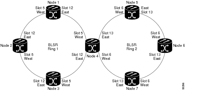
Figure 9-20 shows two BLSRs shared by one ONS 15454. Ring 1 runs on Nodes 1, 2, 3, and 4. Ring 2 runs on Nodes 4, 5, 6, and 7. Two BLSR rings, Ring 1 and Ring 2, are provisioned on Node 4. Ring 1 uses cards in Slots 5 and 12, and Ring 2 uses cards in Slots 6 and 13.
Note
Figure 9-20 A BLSR subtending from a BLSR
After subtending two BLSRs, you can route circuits from nodes in one ring to nodes in the second ring. For example in Figure 9-20, you can route a circuit from Node 1 to Node 7. The circuit would normally travel from Node 1 to Node 4 to Node 7. If fiber breaks occur, for example between Nodes 1 and 4 and Nodes 4 and 7, traffic is rerouted around each ring: in this example, Nodes 2 and 3 in Ring 1 and Nodes 5 and 6 in Ring 2.
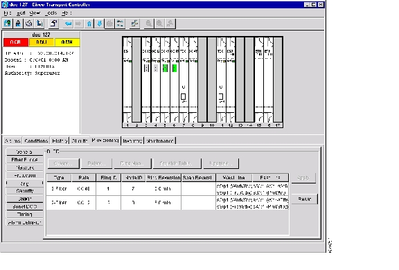
Figure 9-21 Configuring two BLSRs on the same node
9.4 Linear ADM Configurations
You can configure ONS 15454s as a line of add/drop multiplexers (ADMs) by configuring one set of OC-N cards as the working path and a second set as the protect path. Unlike rings, linear (point-to-point) ADMs require that the OC-N cards at each node be in 1+1 protection to ensure that a break to the working line is automatically routed to the protect line.
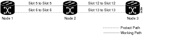
Figure 9-22 shows three ONS 15454s in a linear ADM configuration. Working traffic flows from Slot 6/Node 1 to Slot 6/Node 2, and from Slot 12/Node 2 to Slot 12/Node 3. You create the protect path by placing Slot 6 in 1+1 protection with Slot 5 at Nodes 1 and 2, and Slot 12 in 1+1 protection with Slot 13 at Nodes 2 and 3.
Figure 9-22 A linear (point-to-point) ADM configuration
9.5 Path-Protected Mesh Networks
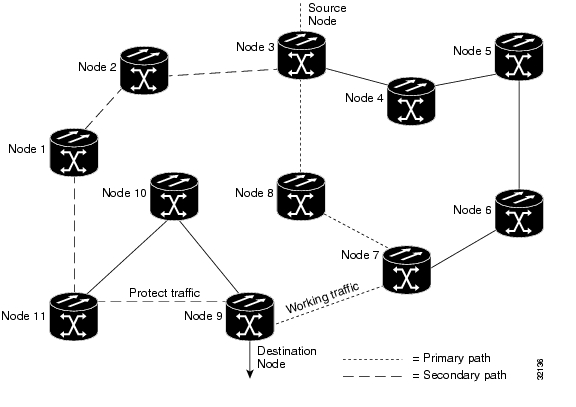
In addition to single BLSRs, UPSRs and ADMs, you can extend ONS 15454 traffic protection by creating path-protected mesh networks (PPMNs). PPMNs include multiple ONS 15454 SONET topologies and extend the protection provided by a single UPSR to the meshed architecture of several interconnecting rings. In a PPMN, circuits travel diverse paths through a network of single or multiple meshed rings. When you create circuits, you can have CTC automatically route circuits across the PPMN, or you can manually route them. You can also choose levels of circuit protection. For example, if you choose full protection, CTC creates an alternate route for the circuit in addition to the main route. The second route follows a unique path through the network between the source and destination and sets up a second set of cross-connections.
For example, in Figure 9-23, a circuit is created from Node 3 to Node 9. CTC determines that the shortest route between the two nodes passes through Node 8 and Node 7, shown by the dotted line, and automatically creates cross-connections at Nodes, 3, 8, 7, and 9 to provide the primary circuit path.
If full protection is selected, CTC creates a second unique route between Nodes 3 and 9 which, in this example, passes through Nodes 2, 1, and 11. Cross-connections are automatically created at Nodes, 3, 2, 1, 11, and 9, shown by the dashed line. If a failure occurs on the primary path, traffic switches to the second circuit path. In this example, Node 9 switches from the traffic coming in from Node 7 to the traffic coming in from Node 11 and service resumes. The switch occurs within 50 ms.
Figure 9-23 A path-protected mesh network
PPMN also allows spans of different SONET line rates to be mixed together in "virtual rings." Figure 9-24 shows Nodes 1, 2, 3, and 4 in a standard OC-48 ring. Nodes 5, 6, 7, and 8 link to the backbone ring through OC-12 fiber. The "virtual ring" formed by Nodes 5, 6, 7, and 8 uses both OC-48 and OC-12.
Figure 9-24 A PPMN virtual ring
9.6 Four Node Configuration
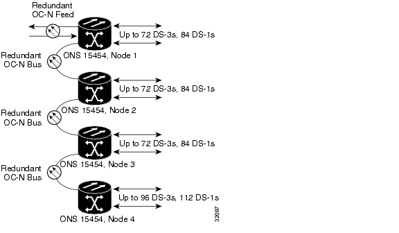
You can link multiple ONS 15454s using their OC-N cards (i.e., create a fiber-optic bus) to accommodate more access traffic than a single ONS 15454 can support. For example, if you need to drop more than 112 DS-1s or 96 DS-3s (the maximum that can be aggregated in a single node), you can link the nodes but not merge multiple nodes into a single ONS 15454. You can link nodes with OC-12 or OC-48 fiber spans as you would link any other two network nodes. The nodes can be co-located in a facility to aggregate more local traffic.
Figure 9-25 shows a four-shelf node setup. Each shelf assembly is recognized as a separate node in the ONS 15454 software interface (Cisco Transport Controller [CTC]), and traffic is mapped using CTC cross-connect options. In the figure, each node uses redundant fiber-optic cards. Node 1 uses redundant OC-N transport and OC-N bus (connecting) cards for a total of four cards, with eight free slots remaining. Nodes 2 and 3 each use two redundant OC-N bus cards for a total of four cards, with eight free slots remaining. Node 4 uses redundant OC-12 bus cards for a total of two cards, with ten free slots remaining. The four node example presented here is one of many ways to set up a multiple-node configuration.
Figure 9-25 A four-shelf node configuration
9.7 Optical Speed Upgrades
A span is the optical fiber connection between two ONS 15454 nodes. In a span (optical speed) upgrade, the transmission rate of a span is upgraded from a lower to a higher OC-N signal but all other span configuration attributes remain unchanged. With multiple nodes, a span upgrade is a coordinated series of upgrades on all nodes in the ring or protection group in which traffic carried at a lower OC-N rate is transferred to a higher OC-N. You can perform in-service span upgrades for the following ONS 15454 cards:
•
•
•
•
Use the XC10G card, the TCC+ card, Software R3.1 or later and the new 15454-SA-ANSI shelf assembly to enable the OC48 IR/STM16 SH AS 1310, OC48 LR/STM16 LH AS 1550, and the OC192 LR/STM64 LH 1550 cards.
To perform a span upgrade, the higher-rate optical card must replace the lower-rate card in the same slot. If the upgrade is conducted on spans residing in a BLSR, all spans in the ring must be upgraded. The protection configuration of the original lower-rate optical card (two-fiber BLSR, four-fiber BLSR, UPSR, and 1+1) is retained for the higher-rate optical card.
When performing span upgrades on a large number of nodes, Cisco recommends that you upgrade all spans in a ring consecutively and in the same maintenance window. Until all spans are upgraded, mismatched card types will be present.
Cisco recommends using the Span Upgrade Wizard to perform span upgrades. Although you can also use the manual span upgrade procedures, the manual procedures are mainly provided as error recovery for the wizard. The Span Upgrade Wizard and the Manual Span Upgrade procedures require at least two technicians (one at each end of the span) who can communicate with each other during the upgrade. Upgrading a span is non-service affecting and will cause no more than three switches, each of which is less than 50 ms in duration.
Note
9.7.1 Span Upgrade Wizard
The Span Upgrade Wizard automates all steps in the manual span upgrade procedure (BLSR, UPSR, and 1+1). The wizard can upgrade both lines on one side of a four-fiber BLSR or both lines of a 1+1 group; the wizard upgrades UPSRs and two-fiber BLSRs one line at a time. The Span Upgrade Wizard requires that spans have DCC enabled.
The Span Upgrade Wizard provides no way to back out of an upgrade. In the case of an abnormal error, you must exit the wizard and initiate the manual procedure to either continue with the upgrade or back out of it. To continue with the manual procedure, examine the standing conditions and alarms to identify the stage in which the wizard failure occurred.
9.7.2 Manual Span Upgrades
Manual Span Upgrades are mainly provided as error recovery for the Span Upgrade Wizard, but they can be used to perform span upgrades. Downgrading can be performed to back out of a span upgrade. The procedure for downgrading is the same as upgrading except that you choose a lower-rate card type.You cannot downgrade if circuits exist on the STSs that will be removed (the higher STSs).
Four manual span upgrade options are available:•
•
•
•
![]()
![]()
![]()
![]()
![]()
![]()
![]()
![]()
Posted: Mon Feb 25 15:38:36 PST 2008
All contents are Copyright © 1992--2008 Cisco Systems, Inc. All rights reserved.
Important Notices and Privacy Statement.