|
|

Table Of Contents
11.2 Cross-Connect Card Capacities
11.4 Multiple Drops for Unidirectional Circuits
11.8 Automatic Circuit Routing
11.8.1 Bandwidth Allocation and Routing
11.8.2 Secondary Sources and Drops
11.10 Constraint-Based Circuit Routing
Circuits and Tunnels
This chapter explains Cisco ONS 15454 STS and VT circuits and VT and DCC tunnels. To provision circuits and tunnels, refer to the Cisco ONS 15454 Procedure Guide.
Chapter topics include:
•
Cross-Connect Card Capacities
•
•
11.1 Circuit Types
For an explanation and examples of circuits and VT tunnels, see the "Cross-Connect Card Capacities" section. You can create unidirectional or bidirectional, revertive or non-revertive circuits. You can have circuits routed automatically or you can manually route them. The auto range feature eliminates the need to individually build circuits of the same type; CTC can create additional sequential circuits if you specify the number of circuits you need and build the first circuit.
You can provision circuits at any of the following points:
•
•
Note
11.2 Cross-Connect Card Capacities
The ONS 15454 XC, XCVT, and XC10G cards perform port-to-port time-division multiplexing (TDM).
•
•
XCs and XCVTs have capacity to terminate 288 STSs, or 144 STS cross-connections (each STS cross-connection uses two STS ports on the cross-connect card STS matrix). XC10Gs have capacity for 1152 STSs or 576 STS cross-connections. Table 11-1 shows STS capacities for the XC, XCVT, and XC10G cards.
Table 11-1 XC, XCVT, and XC10G Card STS Cross-Connect Capacities
XC
288
144
XCVT
288
144
XC10G
1152
576
11.2.1 VT1.5 Cross-Connects
XCVTs and XC10Gs can map up to 24 STSs for VT1.5 traffic. Because one STS can carry 28 VT1.5s, the XCVT and XC10G cards can terminate up to 672 VT1.5s or 336 VT1.5 cross-connects. However, to terminate 336 VT1.5 cross-connects:
•
•
Table 11-2 shows the VT1.5 capacities for ONS 15454 cross-connect cards. All capacities assume each VT1.5-mapped STS carries 28 VT1.5 circuits.
Table 11-2 XC, XCVT, and XC10G VT1.5 Capacities
XC
0
0
0
XCVT
672
336
224
XC10G
672
336
224
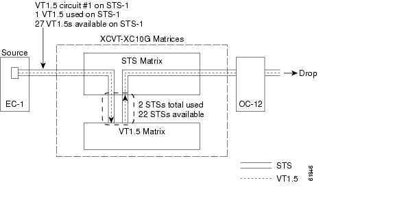
Figure 11-1 shows the logical flow of a VT1.5 circuit through the XCVT/XC10G STS and VT matrices at a BLSR node. The circuit source is an EC-1 card using STS-1. After the circuit is created:
•
•
•
Figure 11-1 Example #1: A VT1.5 circuit in a BLSR
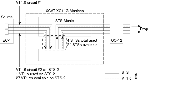
In Figure 11-2, a second VT1.5 circuit is created from the EC-1 card. In this example, the circuit is assigned to STS-2:
•
•
•
Figure 11-2 Example #2: Two VT1.5 circuits in a BLSR
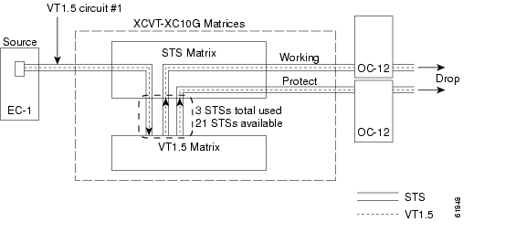
If you create VT1.5 circuits on nodes in a UPSR or 1+1 protection, an additional STS is used for the protect path at the source and drop nodes. Figure 11-3 shows a VT1.5 circuit at a UPSR source node. When the circuit is completed:
•
•
Figure 11-3 Example #3: VT1.5 circuit in a UPSR or 1+1 protection scheme
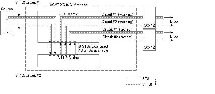
Figure 11-4 shows a second VT1.5 circuit that was created using STS-2. When the second VT1.5 circuit is created:
•
•
Figure 11-4 Example #4: Two VT1.5 circuits in UPSR or 1+1 protection scheme
Unless you create VT tunnels (see the "VT Tunnels" section), VT1.5 circuits use STSs on the XCVT/XC10G VT matrix at each node that the circuit passes through.
•
•
STSs at the pass-through nodes.11.2.2 VT Tunnels
To maximize VT matrix resources, you can tunnel VT1.5 circuits through ONS 15454 pass-through nodes (nodes that are not a circuit source or drop). VT1.5 tunnels provide two benefits:
•
•
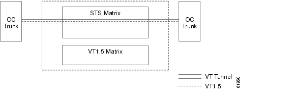
Figure 11-5 shows a VT tunnel through the XCVT and XC10G matrices. No VT1.5-mapped STSs are used by the tunnel, which can carry 28 VT1.5s. However, the tunnel does use two STS matrix ports on each node that it passes through.
Figure 11-5 A VT1.5 tunnel
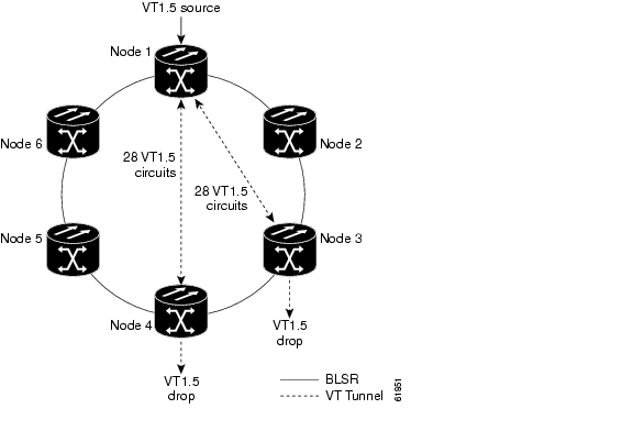
Figure 11-6 shows a six-node ONS 15454 ring with two VT tunnels. One tunnel carries VT1.5 circuits from Node 1 to Node 3. The second tunnel carries VT1.5 circuits from Node 1 to Node 4. Table 11-3 shows the VT1.5-mapped STS usage at each node in a ring based on protection scheme and use of VT tunnels. In the Figure 11-6 example, the circuit travels west through Nodes 2, 3, and 4. Subsequently, VT-mapped STS usage at these nodes is greater than at Nodes 5 and 6.
Figure 11-6 A six-node ring with two VT1.5 tunnels
When planning VT1.5 circuits, weigh the benefits of using tunnels with the need to maximize STS capacity. For example, a VT1.5 tunnel between Node 1 and Node 4 passing (transparently) through Nodes 2 and Node 3 is advantageous if a full STS is used for Node 1 - Node 4 VT1.5 traffic (that is, the number of VT1.5 circuits between these nodes is close to 28). A VT tunnel is required if:
•
•
However, if the Node 1 - Node 4 tunnel will carry only a few VT1.5 circuits, creating a regular VT1.5 circuit between Nodes 1, 2, 3, and 4 might maximize STS capacity.
When you create a VT1.5 circuit, CTC determines whether a tunnel already exists between source and drop nodes. If a tunnel exists, CTC checks the tunnel capacity. If the capacity is sufficient, CTC routes the circuit on the existing tunnel. If a tunnel does not exist, or if an existing tunnel does not have sufficient capacity, CTC displays a dialog box asking whether you want to create a tunnel. Before you create the tunnel, review the existing tunnel availability, keeping in mind future bandwidth needs. In some cases, you may want to manually route a circuit rather than create a new tunnel.
11.3 DCC Tunnels
SONET provides four data communications channels (DCCs) for network element operations, administration, maintenance, and provisioning: one on the SONET Section layer and three on the SONET Line layer. The ONS 15454 uses the Section DCC (SDCC) for ONS 15454 management and provisioning.
You can use the Line DCCs (LDCCs) and the SDCC (when the SDCC is not used for ONS 15454 DCC terminations) to tunnel third-party SONET equipment across ONS 15454 networks. A DCC tunnel end-point is defined by Slot, Port, and DCC, where DCC can be either the SDCC, Tunnel 1, Tunnel 2, or Tunnel 3 (LDCCs). You can link an SDCC to an LDCC (Tunnel 1, Tunnel 2, or Tunnel 3), and an LDCC to an SDCC. You can also link LDCCs to LDCCs and link SDCCs to SDCCs. To create a DCC tunnel, you connect the tunnel end points from one ONS 15454 optical port to another.
Each ONS 15454 can support up to 32 DCC tunnel connections. Table 11-4 shows the DCC tunnels that you can create.
Table 11-4 DCC Tunnels
SDCC
Section
D1 - D3
Yes
Yes
Tunnel 1
Line
D4 - D6
No
Yes
Tunnel 2
Line
D7 - D9
No
Yes
Tunnel 3
Line
D10 - D12
No
Yes
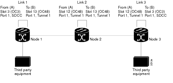
Figure 11-7 shows a DCC tunnel example. Third-party equipment is connected to OC-3 cards at Node 1/Slot 3/Port 1 and Node 3/Slot 3/Port 1. Each ONS 15454 node is connected by OC-48 trunk cards. In the example, three tunnel connections are created, one at Node 1 (OC-3 to OC-48), one at Node 2 (OC-48 to OC-48), and one at Node 3 (OC-48 to OC-3).
Figure 11-7 A DCC tunnel
When you create DCC tunnels, keep the following guidelines in mind:
•
•
•
•
•
11.4 Multiple Drops for Unidirectional Circuits
Unidirectional circuits can have multiple drops for use in broadcast circuit schemes. In broadcast scenarios, one source transmits traffic to multiple destinations, but traffic is not returned back to the source.
When you create a unidirectional circuit, the card that does not have its backplane Rx input terminated with a valid input signal generates a loss of service (LOS) alarm. To mask the alarm, create an alarm profile suppressing the LOS alarm and apply it to the port that does not have its Rx input terminated.
11.5 Monitor Circuits
You can set up secondary circuits to monitor traffic on primary bidirectional circuits. Figure 11-8 shows an example of a monitor circuit. At Node 1, a VT1.5 is dropped from Port 1 of an EC1-12 card. To monitor the VT1.5 traffic, test equipment is plugged into Port 2 of the EC1-12 card and a monitor circuit to Port 2 is provisioned in CTC. Circuit monitors are one-way. The monitor circuit in Figure 11-8 is used to monitor VT1.5 traffic received by Port 1 of the EC1-12 card.
Figure 11-8 A VT1.5 monitor circuit received at an EC1-12 port
Note
11.6 UPSR Circuits
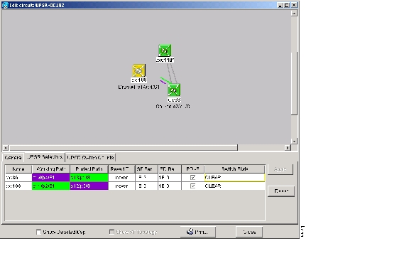
Use the Edit Circuits window to change UPSR selectors and switch protection paths ( Figure 11-9). In this window, you can:
•
•
•
•
Figure 11-9 Editing UPSR selectors
11.7 Path Trace
The SONET J1 Path Trace is a repeated, fixed-length string comprised of 64 consecutive J1 bytes. You can use the string to monitor interruptions or changes to circuit traffic. Table 11-5 shows the ONS 15454 cards that support path trace. DS-1 and DS-3 cards can transmit and receive the J1 field, while the EC-1, OC-3, OC-48AS, and OC-192 can only receive it. Cards not listed in the table do not support the J1 byte.
The J1 path trace transmits a repeated, fixed-length string. If the string received at a circuit drop port does not match the string the port expects to receive, an alarm is raised. Two path trace modes are available:
•
•
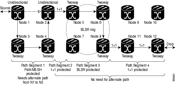
11.8 Automatic Circuit Routing
If you select automatic routing during circuit creation, Cisco Transport Controller (CTC) routes the circuit by dividing the entire circuit route into segments based on protection domains. For unprotected segments of protected circuits, CTC finds an alternate route to protect the segment in a virtual UPSR fashion. Each path segment is a separate protection domain, and each protection domain is protected in a specific fashion (virtual UPSR, BLSR, or 1+1).
The following list provides principles and charactistics of automatic circuit routing:
•
•
•
•
•
11.8.1 Bandwidth Allocation and Routing
Within a given network, CTC will route circuits on the shortest possible path between source and destination based on the circuit attributes, such as protection and type. CTC will consider using a link for the circuit only if the link meets the following requirements:
•
•
•
If CTC cannot find a link that meets these requirements, it displays an error
The same logic applies to VT circuits on VT tunnels. Circuit routing typically favors VT tunnels because, based on topology maintained by circuit routing, VT tunnels are shortcuts between a given source and destination. If the VT tunnel in the route is full (no more bandwidth), CTC asks whether you want to create an additional VT tunnel.
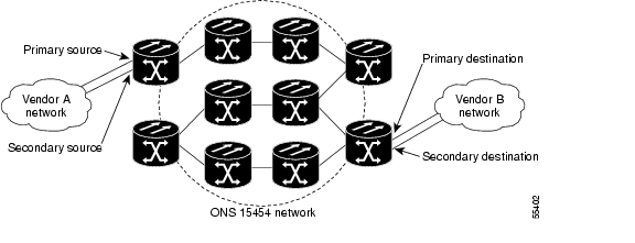
11.8.2 Secondary Sources and Drops
CTC supports secondary sources and drops. Secondary sources and drops typically interconnect two "foreign" networks, as shown in Figure 11-10. Traffic is protected while it goes through a network of ONS 15454s.
Figure 11-10 Secondary sources and drops
Several rules apply to secondary sources and drops:
•
•
•
•
•
•
For bidirectional circuits, CTC creates a UPSR connection at the source node that allows traffic to be selected from one of the two sources on the ONS 15454 network. If you check the Fully Path Protected option during circuit creation, traffic is protected within the ONS 15454 network. At the destination, another UPSR connection is created to bridge traffic from the ONS 15454 network to the two destinations. A similar but opposite path exists for the reverse traffic flowing from the destinations to the sources.
For unidirectional circuits, a UPSR drop-and-continue connection is created at the source node.
11.9 Manual Circuit Routing
Routing circuits manually allows you to:
•
•
•
•
CTC imposes the following rules on manual routes:
•
•
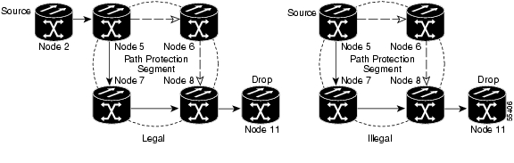
Figure 11-11 Alternate paths for virtual UPSR segments
•
•
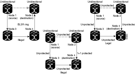
Figure 11-12 Mixing 1+1 or BLSR protected links with a UPSR
•
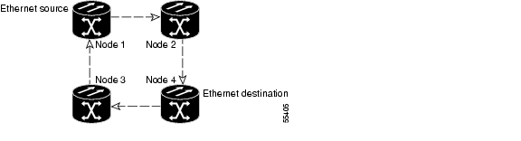
Figure 11-13 Ethernet shared packet ring routing
•
Figure 11-14 Ethernet and UPSR
•
If Fully Path Protected is chosen, CTC verifies that the route selection is protected at all segments. A route can have multiple protection domains with each domain protected by a different mechanism.
The following tables summarize the available node connections. Any other combination is invalid and will generate an error.
Although virtual UPSR segments are possible in VT tunnels, VT tunnels are still considered unprotected. If you need to protect VT circuits either use two independent VT tunnels that are diversely routed or use a VT tunnel that is routed over only 1+1 or BLSR (or a mix) links.
11.10 Constraint-Based Circuit Routing
When you create circuits, you can choose Fully Protected Path to protect the circuit from source to destination. The protection mechanism used depends on the path CTC calculates for the circuit. If the network is comprised entirely of BLSR and/or 1+1 links, or the path between source and destination can be entirely protected using 1+1 and/or BLSR links, no PPMN (virtual UPSR) protection is used.
If virtual UPSR (PPMN) protection is needed to protect the path, set the level of node diversity for the PPMN portions of the complete path on the Circuit Creation dialog box:
•
•
•
When you choose automatic circuit routing during circuit creation, you have the option to require and/or exclude nodes and links in the calculated route. You can use this option to:
•
•
CTC considers required nodes and links to be an ordered set of elements. CTC treats the source nodes of every required link as required nodes. When CTC calculates the path, it makes sure the computed path traverses the required set of nodes and links and does not traverse excluded nodes and links.
The required nodes and links constraint is only used during the primary path computation and only for PPMN domains/segments. The alternate path is computed normally; CTC uses excluded nodes/links when finding all primary and alternate paths on PPMNs.
![]()
![]()
![]()
![]()
![]()
![]()
![]()
![]()
Posted: Mon Feb 25 15:49:45 PST 2008
All contents are Copyright © 1992--2008 Cisco Systems, Inc. All rights reserved.
Important Notices and Privacy Statement.