|
|

Table Of Contents
3.1 Air Filter Inspection and Replacement
3.2 Fan-Tray Assembly Replacement
3.3 Alarm Interface Panel Replacement
3.4 Replace the Alarm Interface Panel
3.6 Database Backup and Restore
3.7 Reverting to an Earlier Software Load
3.9 TCC Card to TCC+ Card Upgrade
3.10 XC Card to XCVT Card Upgrade
3.11 XC/XCVT Card to XC10G Card Upgrade
3.12 DS3/DS3N Card to DS3E/DS3EN Card Upgrade
3.14 Protection Group Switching
3.15 Electrical Interface Assembly Replacement
3.15.2 EIA Replacement Procedures
Maintenance
This chapter describes maintenance information and procedures for Cisco ONS 15454, including:
•
Air filter inspection and replacement
•
•
•
•
•
•
•
•
•
•
•
•
•
•
•
3.1 Air Filter Inspection and Replacement
The ONS 15454 contains an air filter that you should remove and visually inspect approximately every 30 days, depending on the cleanliness of the operating environment. NEBS 3E and later versions of the ONS 15454 use a reusable air filter that is installed either beneath the fan-tray assembly or in the optional external filter brackets. Earlier versions of the ONS 15454 use a disposable air filter that is installed beneath the fan-tray assembly only. For more information about filter brackets and air filter installation, see the "Installation" chapter of the Cisco ONS 15454 Installation and Operations Guide.
Warning
3.1.1 Reusable Air Filter
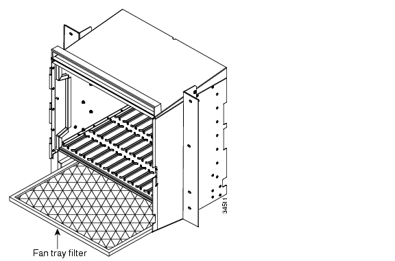
The reusable filter is made of a gray, open-cell, polyurethane foam that is specially coated to provide fire and fungi resistance. NEBS 3E and later versions of the ONS 15454 use a reusable air filter. Figure 3-1 illustrates a reusable fan-tray air filter in an external filter bracket. When the filter is dirty, remove the filter and clean it by either vacuuming the filter or running water through it. Because the filter material is delicate, only a very low-power vacuum should be used. If you are cleaning with water, make sure the filter is completely dry (dry time is at least eight hours) before replacing it in the fan-tray assembly. Spare filters should be kept in stock.
Figure 3-1 A reusable fan-tray air filter in an external filter bracket
Procedure: Inspect and Clean the Reusable Air Filter
Step 1
Step 2
Step 3
Step 4
Note
Step 5
Warning
a.
b.
Step 6
Caution
Note
Step 7
3.1.2 Disposable Air Filter
Versions prior to the NEBS 3E version of the ONS 15454 use a disposable air filter. The disposable filter is made of spun white polyester that is flame retardant. This disposable filter is not designed to be cleaned. You can order air filter replacements from Cisco (Cisco P/N 47-01-00001) or from Universal Air Filter, model PE-5 (Universal Air Filter Co., 1624 Sauget Ind. Parkway, Sauget, IL 62206).
Note
Procedure: Inspect and Replace the Disposable Air Filter
Step 1
Step 2
Step 3
Step 4
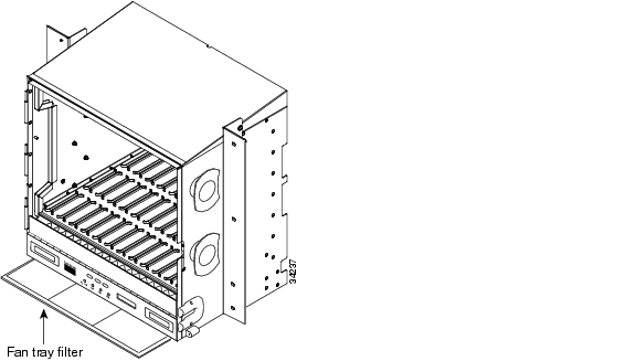
Figure 3-2 Inserting or removing the fan-tray assembly
Step 5
Step 6
Step 7
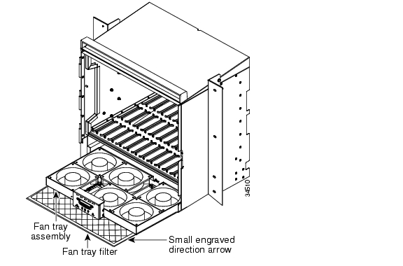
Figure 3-3 Inserting or removing a disposable fan-tray air filter
Step 8
Step 9
Step 10
Step 11
Step 12
Step 13
3.2 Fan-Tray Assembly Replacement
If one or more fans fail on the fan-tray assembly, replace the entire assembly. You cannot replace individual fans. The red Fan Fail LED on the front of the fan tray illuminates when one or more fans fail. The red Fan Fail LED clears after you install a working fan tray.
Caution
Note
Procedure: Replace the Fan-Tray Assembly
To replace the fan-tray assembly, it is not necessary to move any of the cable management facilities. You can remove the fan-tray assembly using the retractable handles and replace it by pushing until it plugs into the receptacle on the back panel.
Caution
Step 1
Step 2
Step 3
Step 4
If you are replacing the fan-tray air filter and it is installed in the external bottom bracket, you can slide the existing air filter out of the bracket and replace it at anytime.
Note
For more information on the fan-tray air filter, see the "Air Filter Inspection and Replacement" section.
Step 5
Step 6
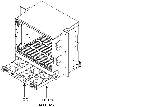
Figure 3-4 Removing or replacing the fan-tray assembly
3.3 Alarm Interface Panel Replacement
3.4 Replace the Alarm Interface Panel
This procedure replaces an existing AIP with a new AIP on an in-service system without affecting traffic. It requires a #2 phillips screw driver.
Caution
Caution
Caution
Note
Step 1
a.
b.
c.
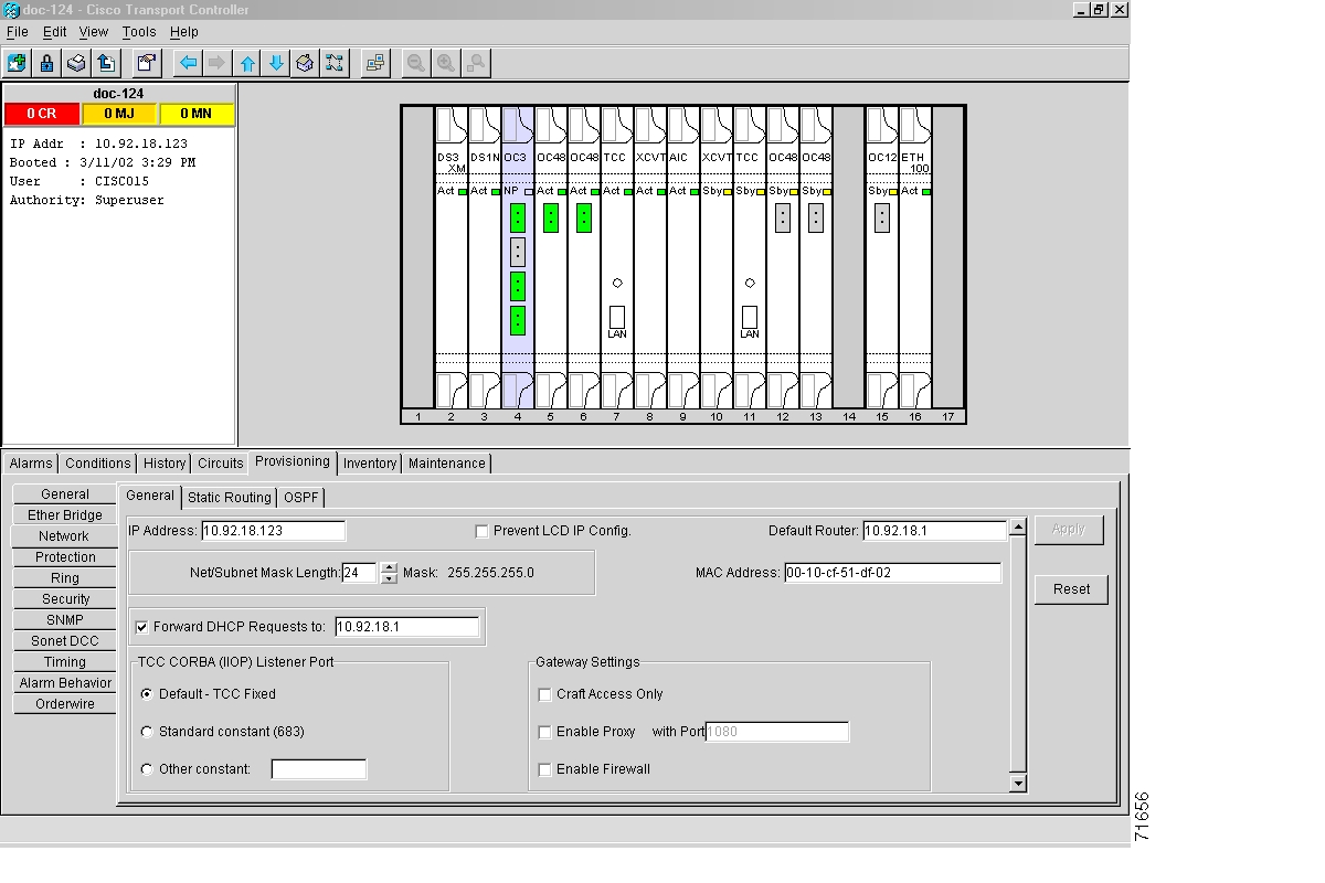
Step 2
a.
b.
c.
Figure 3-5 Find the MAC address
Step 3
Step 4
Step 5
Figure 3-6 Lower backplane cover
Step 6
Step 7
Note
Step 8
Step 9
Step 10
Caution
Caution
Step 11
Step 12
Step 13
Step 14
Step 15
Caution
Step 16
a.
b.
Note
Step 17
a.
b.
Note
Step 18
Step 19
Step 20
a.
b.
Step 21
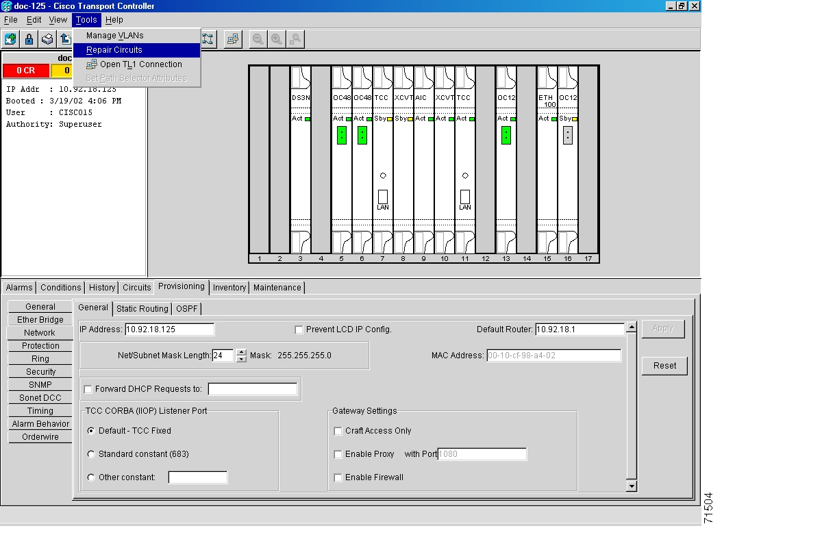
Step 22
Figure 3-7 Repair Circuits in the Menu Bar
Step 23
Figure 3-8 Repairing circuits
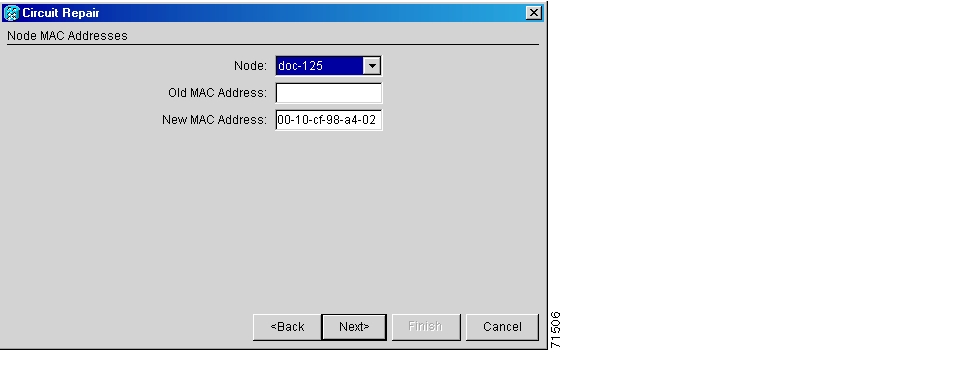
Step 24
a.
b.
c.
Figure 3-9 Recording the old MAC address before replacing the AIP
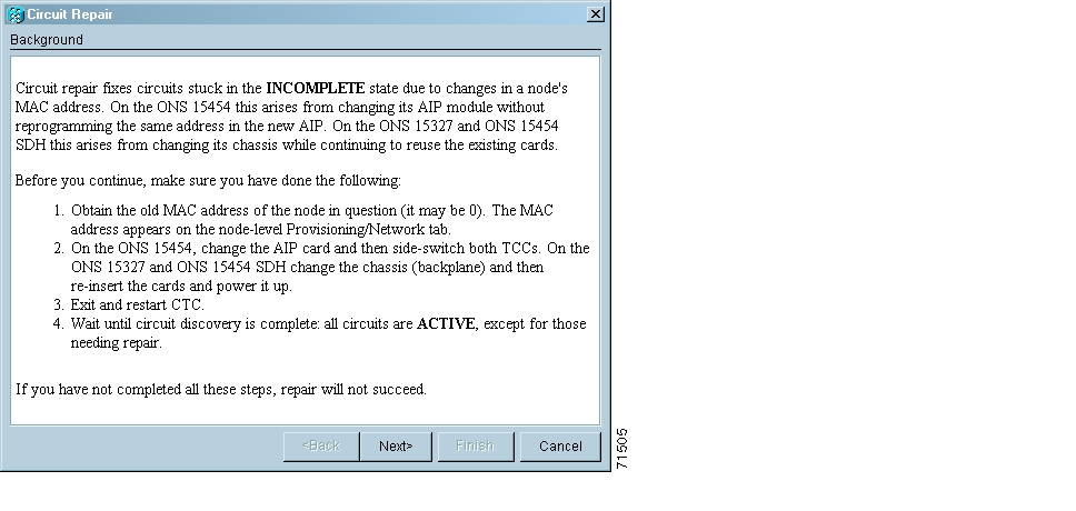
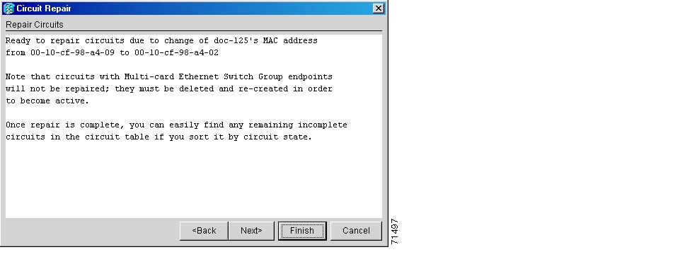
Step 25
Figure 3-10 Circuit repair information
Note
Step 26
Step 27
Step 28
Step 29
3.5 System Reset
You can reset the ONS 15454 TCC+ cards by using the Cisco Transport Controller (CTC) software, or by physically reseating a TCC+ card (card pull). A software-initiated reset reboots the TCC+ and reloads the operating system and the application software. Additionally, a card pull reset temporarily removes power from the TCC+ and clears all buffer memory.
You can apply a software-initiated reset to either an active or standby TCC+ without affecting traffic, but you should only perform a card pull on a standby TCC+. If you need to perform a card pull on an active TCC+, put the TCC+ into standby mode first by performing a software-initiated reset on the card.
Note
Warning
Procedure: Perform a Software-Initiated Reset
Step 1
Step 2
Step 3
Step 4
Step 5
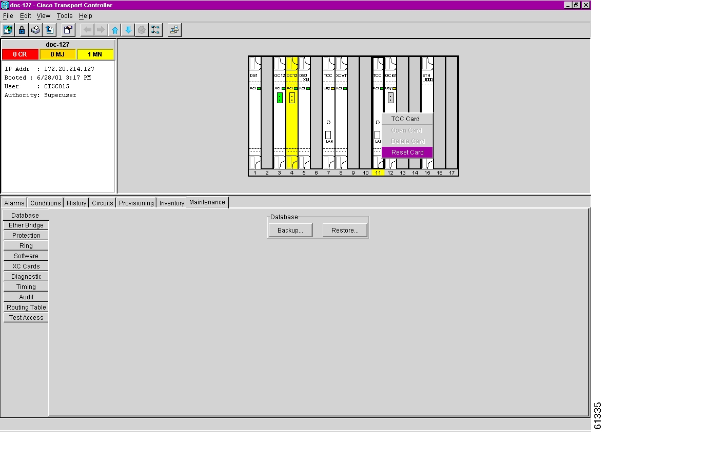
Step 6
Figure 3-11 Performing a software-initiated reset from the TCC+ card pull-down menu
Procedure: Perform a Card Pull
Note
Step 1
Step 2
Step 3
Step 4
Note
3.6 Database Backup and Restore
Each TCC+ card installed in the ONS 15454 contains two copies of the database. A save to the flash memory is written to the standby database, and the standby database then becomes the active database. The previously active database then becomes available for writing the next time. With dual TCC+s, the standby TCC+ keeps both copies of the database synchronized with the active TCC+ as changes are made so that it is ready to take over control as needed. You can also store a back-up version of the database on the workstation running CTC. Backing up the database should be part of a regular ONS 15454 maintenance program at approximately weekly intervals and should also be completed when preparing an ONS 15454 for a pending natural disaster, such as a flood or fire.
Note
Caution
Caution
Procedure: Back up the Database
Step 1
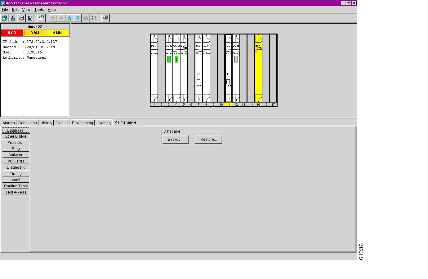
Step 2
Figure 3-12 Backing up the TCC+ database
Step 3
Step 4
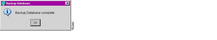
Step 5
Figure 3-13 Confirming a database backup
Step 6
Procedure: Restore the Database
Step 1
Step 2
Figure 3-14 Restoring the TCC+ database
Step 3
Step 4
Step 5
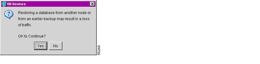
Step 6
The DB Restore dialog box appears. A restore from another node will affect traffic.
Figure 3-15 Restoring the database—traffic loss warning
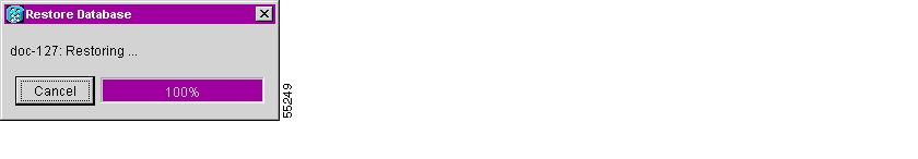
Step 7
The Restore Database dialog box monitors the file transfer.
Figure 3-16 Restoring the database - in-process notification
Step 8
Step 9
3.7 Reverting to an Earlier Software Load
Prior to Release 2.2.1, the ONS 15454 could not revert to an earlier software database without deleting the current database and losing both cross-connect and DCC connectivity. The revert would result in a loss of traffic until the user manually restored the previous database or recreated the existing circuits and provisioning.
Reverting to a 2.2.1 or later load will switch to the older software load and its attendant database without affecting traffic or DCC connectivity. This feature requires dual TCC+ cards and CTC software Release 2.2.1 or later as the protect version.
When you click the Activate button after a software upgrade, the TCC+ copies the current working database and saves it in a reserved location in the TCC+ flash memory. If you later need to revert to the original working software load from the protect software load, the saved database installs automatically. You do not need to restore the database manually or recreate circuits.
Tip
Note
Note
Procedure: Revert to an Earlier Software Load
Step 1
Step 2
Step 3
Step 4
Step 5
Step 6
Step 7
Step 8
Step 9
Step 10
Step 11
The Revert button activates the protect software load. The ONS 15454 reboots and loses the connection to CTC.
Step 12
This may take as long as 30 minutes.
Step 13
Step 14
The browser downloads the CTC applet for the standby software load.
3.8 Card Replacement
To replace an ONS 15454 card with another card of the same type, you do not need to make any changes to the database; remove the old card and replace it with a new card. To replace a card with a card of a different type, physically remove the card and replace it with the new card, then delete the original card from CTC. Follow the "Switch Traffic and Replace an In-Service Cross-Connect Card" procedure to replace an XC/XCVT card.
Caution
Note
Note
Warning
To upgrade cards, refer to the specific upgrade procedure you need:
•
•
•
•
For more information on cards and card compatibility see Chapter 4, "Card Reference."
Procedure: Switch Traffic and Replace an In-Service Cross-Connect Card
Caution
An XC/XCVT reset can cause a linear 1+1 OC-N protection switch or a BLSR protection switch.
Step 1
a.
b.
c.
In a BLSR, place a lockout on the East and West cards of the nodes adjacent to the XC/XCVT switch node; for example, to switch the XC/XCVT on Node B, place the lockout on the West card of Node A and on the East card of Node C. No lockout is necessary on Node B. Before the lockout is set, verify that the BLSR is not switched. If a lockout is set while the BLSR is switched, traffic can be lost.
<------East [Node A] West------East [Node B] West------East [Node C] West------>
In a 1+1 protection scheme, place a lockout on the protect card and verify that the traffic is traveling over the working span before setting the lockout.
Step 2
Note
Step 3
a.
b.
c.
Note
Step 4
Step 5
The replacement card boots up and becomes ready for service after approximately one minute.
Step 6
3.9 TCC Card to TCC+ Card Upgrade
Caution
The TCC card supports ONS 15454 Release 2.2.2 and earlier software versions. The TCC+ card supports ONS 15454 Release 2.2.0 and later software versions.
Verify that the ONS 15454 is running Release 2.2.0 software before you begin the upgrade procedure. The TCC to TCC+ upgrade process requires Release 2.2.0 to support the TCC/TCC+ mismatch that occurs briefly during the TCC to TCC+ upgrade process.
The ACT/STBY LED on the faceplate of the TCC/TCC+ card indicates whether the card is in active or standby mode. A green ACT/STBY LED indicates an active card and an amber light indicates a standby card. See Chapter 5 for more information about the TCC/TCC+ card.
Procedure: Upgrade the TCC Card to the TCC+ Card
Step 1
a.
b.
c.
d.
e.
Note
Note
Step 2
Step 3
Figure 3-17 Initiating a software reset on the TCC card
Wait for the TCC to reboot. The ONS 15454 switches the standby TCC+ card to active mode.
Step 4
Step 5
a.
b.
c.
d.
e.
The ONS 15454 boots up the second TCC+ card. The second TCC+ must also copy the system software, which can take up to 20 or 30 minutes. The MEA alarm clears when the ONS 15454 recognizes the matching TCC+s.
3.10 XC Card to XCVT Card Upgrade
This section explains how to replace dual XC cards with dual XCVT cards in an ONS 15454 with live traffic. The procedure is non-service affecting, that is, the upgrade will cause a switch less than 50 ms in duration.
Note
Procedure: Upgrade the XC Card to the XCVT Card
Upgrading XC cards to XCVT requires that the ONS 15454 is running CTC Release 2.0 or later. Two XC cards must be installed in the ONS 15454, and two XCVT cards must be available for installation. An XC switch can cause a linear 1+1 OC-N protection switch or a BLSR protection switch.
Step 1
a.
b.
c.
In a BLSR, place a lockout on the East and West cards of the nodes adjacent to the XC switch node; for example, to switch the XC on Node B, place the lockout on the West card of Node A and on the East card of Node C. No lockout is necessary on Node B. Before the lockout is set, verify that the BLSR is not switched. If a lockout is set while the BLSR is switched, traffic can be lost.
<------East [Node A] West------East [Node B] West------East [Node C] West------>
In a 1+1 protection scheme, place a lockout on the protect card and verify that the traffic is traveling over the working span before setting the lockout.
Step 2
Note
Step 3
a.
b.
c.
d.
The fail LED above the ACT/STBY LED becomes red, blinks for several seconds, and turns off. The ACT/STBY LED turns amber and stays lit.
e.
Step 4
Step 5
Step 6
Note
Step 7
a.
b.
c.
d.
e.
The upgrade is complete when the second XCVT card boots up and becomes the standby XCVT.
Step 8
3.11 XC/XCVT Card to XC10G Card Upgrade
Note
Note
This section explains how to upgrade dual XC/XCVT cards with dual XC10G cards in the ONS 15454-SA-ANSI with live traffic. The procedure is non-service affecting, that is, the upgrade will cause a switch less than 50 ms in duration.
Procedure: Upgrade the XC/XCVT Card to the XC10G Card
Upgrading XC/XCVT cards to XC10G requires that the ONS 15454 is running CTC Release 3.1 or later. Two XC/XCVT cards must be installed in the ONS 15454-SA-ANSI, and two XC10G cards must be available for installation. An XC/XCVT switch can cause a linear 1+1 OC-N protection switch or a BLSR protection switch.
Step 1
a.
b.
c.
In a BLSR, place a lockout on the East and West cards of the nodes adjacent to the XC/XCVT switch node; for example, to switch the XC/XCVT on Node B, place the lockout on the West card of Node A and on the East card of Node C. No lockout is necessary on Node B. Before the lockout is set, verify that the BLSR is not switched. If a lockout is set while the BLSR is switched, traffic can be lost.
<------East [Node A] West------East [Node B] West------East [Node C] West------>
In a 1+1 protection scheme, place a lockout on the protect card and verify that the traffic is traveling over the working span before setting the lockout.
Step 2
Note
Step 3
a.
b.
c.
d.
The fail LED above the ACT/STBY LED becomes red, blinks for several seconds, and turns off. The ACT/STBY LED turns amber and stays lit.
e.
Step 4
Step 5
Step 6
Note
Step 7
a.
b.
c.
d.
e.
The upgrade is complete when the second XC10G card boots up and becomes the standby XC10G.
Step 8
3.12 DS3/DS3N Card to DS3E/DS3EN Card Upgrade
You can perform in-service DS3E upgrades for the following ONS 15454 cards:
•
•
Procedure: Upgrade the DS3 Card to the DS3E Card (or the DS3N Card to the DS3EN Card)
Upgrading to DS3E or DS3EN cards requires that the ONS 15454 is running CTC Release 3.1 or later. Upgrades must be performed between two N-type cards or two non-N-type cards. You cannot upgrade between an N-type card and a non-N-type card. When physically replacing the card, the new card must be in same slot as the old card. The DS3E card upgrade supports 1:1 and 1:N protection schemes. The procedure is non-service affecting, that is, the upgrade will cause a switch less than 50 ms in duration.
Note
Note
Note
Step 1
Note
a.
b.
c.
d.
e.
Step 2
a.
b.
Step 3
Step 4
Step 5
Step 6
a.
b.
Step 7
Wait for the IMPROPRMVL alarm to clear and the card to become standby.
Step 8
a.
b.
c.
d.
e.
Step 9
Note
Procedure: Downgrade a DS3 or DS3N Card
Downgrading can be performed to back out of an upgrade. All ports must be provisioned as UNFRAMED and not have the Path Trace enabled.
Note
The procedure for downgrading is the same as upgrading except you choose DS3 or DS3N from the Change Card pull-down menu. To begin the downgrade, right click on the slot to be downgraded and choose Change Card from the pull-down menu as instructed above in Step 4 of the upgrade. Follow the remaining steps of the upgrade until the downgrade is complete.
3.13 Span Upgrades
A span is the optical fiber connection between two ONS 15454 nodes. In a span upgrade, the transmission rate of a span is upgraded from a lower to a higher OC-N signal but all other span configuration attributes remain unchanged. With multiple nodes, a span upgrade is a coordinated series of upgrades on all nodes in the ring or protection group in which traffic carried at a lower OC-N rate is transferred to a higher OC-N. You can perform in-service span upgrades for the following ONS 15454 cards:
•
•
•
Use the XC10G card, the TCC+ card, Software R3.1 or later, and the new 15454-SA-ANSI shelf assembly to enable the OC48 IR/STM16 SH AS 1310, OC48 LR/STM16 LH AS 1550, and the OC192 LR/STM64 LH 1550 cards. See Chapter 4, "Card Reference," for more information on card compatibility.
To perform a span upgrade, the higher-rate optical card must replace the lower-rate card in the same slot. If the upgrade is conducted on spans residing in a BLSR, all spans in the ring must be upgraded. The protection configuration of the original lower-rate optical card (two-fiber BLSR, four-fiber BLSR, UPSR, and 1+1) is retained for the higher-rate optical card.
When performing span upgrades on a large number of nodes, Cisco recommends that you upgrade all spans in a ring consecutively and in the same maintenance window. Until all spans are upgraded, mismatched card types will be present.
Cisco recommends using the Span Upgrade Wizard to perform span upgrades. Although you can also use the manual span upgrade procedures, the manual procedures are mainly provided as error recovery for the wizard. The Span Upgrade Wizard and the Manual Span Upgrade procedures require at least two technicians (one at each end of the span) who can communicate with each other during the upgrade. Upgrading a span is non-service affecting and will cause no more than three switches, each of which is less than 50 ms in duration.
Note
Note
Warning
3.13.1 Span Upgrade Wizard
The Span Upgrade Wizard automates all steps in the manual span upgrade procedure (BLSR, UPSR, and 1+1). The wizard can upgrade both lines on one side of a four-fiber BLSR or both lines of a 1+1 group; the wizard upgrades UPSRs and two-fiber BLSRs one line at a time. The Span Upgrade Wizard requires that spans have DCC enabled.
The Span Upgrade Wizard provides no way to back out of an upgrade. In the case of an abnormal error, you must exit the wizard and initiate the manual procedure to either continue with the upgrade or back out of it. To continue with the manual procedure, examine the standing conditions and alarms to identify the stage in which the wizard failure occurred.
Note
Note
BLSR Out of Sync alarms will be raised during span upgrades and will clear when the upgrade of all nodes is complete; a four-node BLSR can take up to five minutes to clear all of the Out of Sync alarms. Allow extra time for a large BLSR to clear all of the Out of Sync alarms.
Note
Procedure: Perform a Span Upgrade Using the Span Upgrade Wizard
The following procedure shows the Span Upgrade Wizard upgrading the first line of a two-fiber BLSR from OC-48 to OC-192.
Step 1
a.
b.
An unresolved alarm or abnormal condition is the most probable reason for upgrade failure.
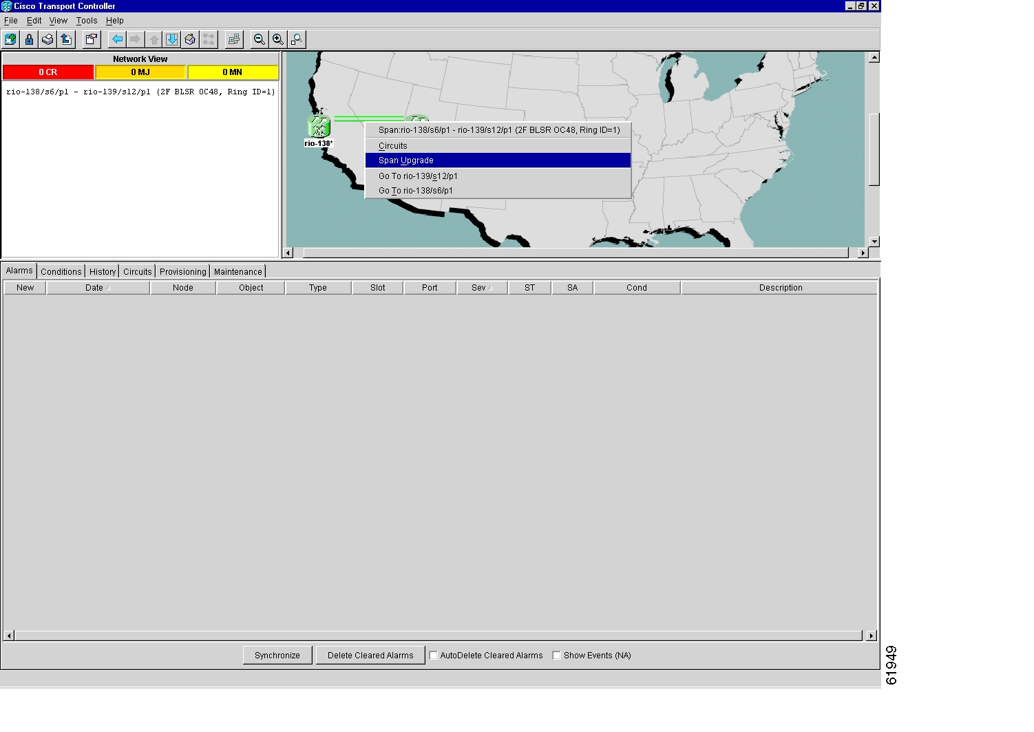
Step 2
Step 3
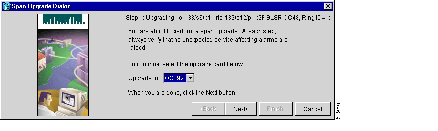
Figure 3-18 Span pull-down menu
The first Span Upgrade Dialog box appears ( Figure 3-19). Follow the instructions on the dialog box and the wizard will lead you through the rest of the span upgrade. The <Back button is only enabled on Step 2 of the wizard; because you cannot back out of an upgrade via the wizard, exit the wizard and initiate the manual procedure if you need to back out of the upgrade at any point beyond Step 2.
Figure 3-19 Beginning the Span Upgrade Wizard
Note
Note
3.13.2 Manual Span Upgrades
Manual Span Upgrades are mainly provided as error recovery for the Span Upgrade Wizard, but they can be used to perform span upgrades. Downgrading can be performed to back out of a span upgrade. The procedure for downgrading is the same as upgrading except that you choose a lower-rate card type.You cannot downgrade if circuits exist on the STSs that will be removed (the higher STSs).
Choose from four manual span upgrade options:•
•
•
•
Note
BLSR Out of Sync alarms will be raised during span upgrades and will clear when the upgrade of all nodes is complete. Allow extra time for a large BLSR to clear all of the Out of Sync alarms.
Note
Procedure: Perform a Manual Span Upgrade on a Two-Fiber BLSR
All spans connecting the nodes in a BLSR must be upgraded before the added bandwidth is available.
Step 1
a.
b.
An unresolved alarm or abnormal condition is the most probable reason for upgrade failure.
Step 2
a.
b.
c.
Step 3
Step 4
Step 5
Step 6
Step 7
Step 8
Wait for the IMPROPRMVL alarm to clear and the cards to become active.
Note
Note
Step 9
a.
b.
c.
The forced switch clears and traffic is running. If you have lost traffic, perform a downgrade. The procedure for downgrading is the same as upgrading except that you choose a lower-rate card.
Note
Step 10
When all spans in the BLSR have been upgraded, the span upgrade is complete.Procedure: Perform a Manual Span Upgrade on a Four-Fiber BLSR
When upgrading a four-fiber BLSR, you can upgrade both working and protect lines with a single force command. All spans in a BLSR must be upgraded before added bandwidth will be available.
Step 1
a.
b.
An unresolved alarm or abnormal condition is the most probable reason for upgrade failure.
Step 2
a.
b.
c.
Step 3
Step 4
Step 5
Step 6
Step 7
Step 8
Wait for the IMPROPRMVL alarm to clear and the cards to become active.
Note
Note
Step 9
a.
b.
c.
The forced switch clears and traffic is running. If you have lost traffic, perform a downgrade. The procedure for downgrading is the same as upgrading except that you choose a lower-rate card.
Note
Step 10
When all spans in the BLSR have been upgraded, the span upgrade is complete.
Procedure: Perform a Manual Span Upgrade on a UPSR
Step 1
a.
b.
An unresolved alarm or abnormal condition is the most probable reason for upgrade failure.
Step 2
a.
b.
c.
Step 3
Step 4
Step 5
Step 6
Step 7
Step 8
Wait for the IMPROPRMVL alarm to clear and the cards to become active.
Note
Note
Step 9
a.
b.
c.
The forced switch clears and traffic is running. If you have lost traffic, perform a downgrade. The procedure for downgrading is the same as upgrading except that you choose a lower-rate card.
Note
Step 10
Procedure: Perform a Manual Span Upgrade on a 1+1 Protection Group
When upgrading a 1+1 group, upgrade the protect line first regardless of which line is active. Both lines in a 1+1 group must be upgraded before the added bandwidth will be available.
Note
Step 1
a.
b.
An unresolved alarm or abnormal condition is the most probable reason for upgrade failure.
Step 2
a.
b.
c.
d.
e.
Step 3
Step 4
Step 5
Step 6
Step 7
Step 8
Step 9
Wait for the IMPROPRMVL alarm to clear and the cards to become standby.
Note
Note
Step 10
a.
b.
c.
d.
e.
The forced switch clears and traffic is running. If you have lost traffic, perform a downgrade. The procedure for downgrading is the same as upgrading except that you choose a lower-rate card.
Note
Step 11
When the other line in the 1+1 has been upgraded, the span upgrade is complete.
3.14 Protection Group Switching
Protection group switching allows you to prohibit traffic from switching to a specified card using the Maintenance > Protection tabs. Protection group switching can be accomplished by applying a Lock On or a Lock Out to a specified card. When the Lock On state is applied to a specified working or protect card, any traffic which is currently on that card will remain on that card and will be unable to switch to the opposite card. When the Lock Out state is applied to a specified working or protect card, any traffic which is currently on that card will be switched to the opposite card. A combination of Lock On and Lock Out is allowed in 1:1 and 1:N protection; for example, a Lock On on the working card and a Lock Out on the protect card.
Note
Procedure: Apply a Lock On
Note
To inhibit traffic from being switched from one card to another, apply a Lock On. Identify which protection group you have to determine which card can be placed in a Lock On state:
•
•
•
Step 1
Step 2
Step 3
Step 4
Step 5
The Lock On has been applied and traffic cannot be switched to the opposite card. To clear the Lock On, see the "Clear a Lock On or Lock Out" procedure.
Procedure: Apply a Lock Out
Note
To switch traffic from one card to another, apply a Lock Out. Identify which protection group you have to determine which card can be placed in a Lock Out state:
•
•
•
Step 1
Step 2
Step 3
Step 4
Step 5
The lock out has been applied and traffic is switched to the opposite card. To clear the Lock Out, see the "Clear a Lock On or Lock Out" procedure.
Procedure: Clear a Lock On or Lock Out
Step 1
Step 2
Step 3
Step 4
The Lock On or Lock Out is cleared.
3.15 Electrical Interface Assembly Replacement
Electrical interface assemblies (EIAs) provide cable connection points on the back of the ONS 15454 and come in several configurations that work with different cards and connections (see Table 3-1). For more information about EIAs, see the "Installation" chapter of the Cisco ONS 15454 Installation and Operations Guide.
EIAs have two sides. As you face the rear of the ONS 15454 shelf assembly, the right-hand side is the A side and the left-hand side is the B side. You can install EIAs on one or both sides of the ONS 15454 backplane in any combination. For example, you can use an AMP Champ EIA on side A and a BNC EIA on side B. The top of the EIA connector columns are labelled with the corresponding slot number, and EIA connector pairs are marked Tx and Rx to correspond to transmit and receive cables. EIAs come pre-installed on the ONS 15454 when ordered with the node.
3.15.1 EIA Types
Table 3-1 gives the product numbers and common names for EIAs.
Note
3.15.2 EIA Replacement Procedures
The replacement procedure is the same for all the EIA types. However, installing the AMP Champ EIA requires the additional step of attaching the fastening plate to the bottom of the connector row. Before you attach a new EIA, you must remove the backplane cover or EIA already attached to the ONS 15454.
Procedure: Remove the Backplane Cover or EIA
Step 1
Step 2
Note
Step 3
Step 4
Note
Procedure: Install the EIAs
Step 1
Step 2
Step 3
Step 4
Step 5
Due to the large number of BNC connectors on the High-Density BNC EIA, you might require a special tool for inserting and removing BNC EIAs ( Figure 3-20). This tool also helps with ONS 15454 patch panel connections.
Figure 3-20 BNC insertion and removal tool
This tool can be obtained with P/N 227-T1000 from:
Amphenol USA (www.amphenol.com)
One Kennedy Drive
Danbury, CT 06810
Phone: 203-743-9272 Fax: 203-796-2032
This tool can be obtained with P/N RT-1L from:
Trompeter Electronics Inc. (www.trompeter.com)
31186 La Baya Drive
Westlake Village, CA 91362-4047
Phone: (800) 982-2629 Fax: (818) 706-1040
3.16 Fiber Cleaning
No special instructions apply to cleaning fibers connected to ONS 15454s. Clean the fiber according to local site practice. If no local practice exists, use a CLETOP Real-Type or equivalent fiber-optic cleaner and follow the instructions accompanying the product. An optical fiber maintenance kit can be ordered from Speer Fiber Optics (www.speerfiberoptics.com), part number SFO-1400 NN-A.
3.17 Powering Down a Node
Note
Caution
Warning
Procedure: Power Down a Node
Step 1
Step 2
a.
b.
Note
Step 3
a.
b.
If no circuits are displayed, skip to Step 4.
Step 4
Step 5
Step 6
Step 7
Step 8
Step 9
Step 10
Step 11
Step 12
Step 13
![]()
![]()
![]()
![]()
![]()
![]()
![]()
![]()
Posted: Fri Feb 22 15:52:43 PST 2008
All contents are Copyright © 1992--2008 Cisco Systems, Inc. All rights reserved.
Important Notices and Privacy Statement.