|
|

Table Of Contents
Installing the Cisco ONS 15454
Four-Shelf and Zero-Shelf Bay AssemblyObtaining Optical Networking Information
Where to Find Safety and Warning Information
Cisco Optical Networking Product Documentation CD-ROM
Obtaining Documentation, Obtaining Support, and Security Guidelines
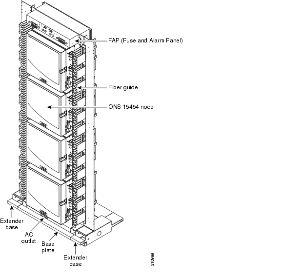
Cisco ONS 15454 Four-Shelf and Zero-Shelf Bay Assembly Overview
Install the ONS 15454 Four-Shelf or Zero-Shelf Bay Assembly
Replace Side A or Side B of the FAP
Central Office Ground to Bay Wire Ground
ONS 15454 Bay Extender Kit (5-inch)
ONS 15454 Bay End Plate Cover Kit
Installing the Cisco ONS 15454
Four-Shelf and Zero-Shelf Bay Assembly
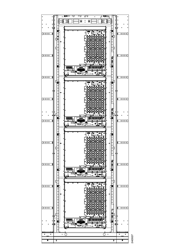
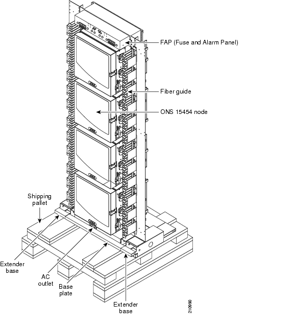
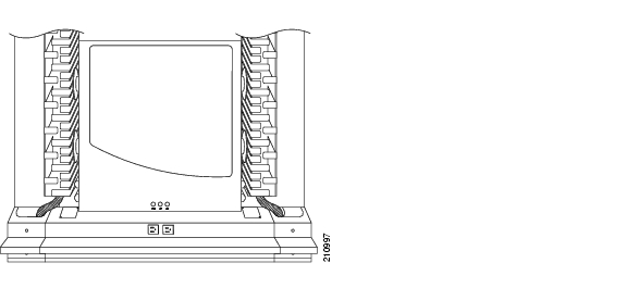
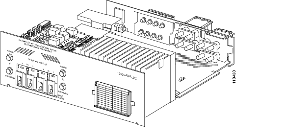
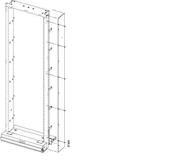
This guide describes how to unpack and install the Cisco ONS 15454 four-shelf and zero-shelf bay assembly. Because it is a complete system, installation simply requires you to remove the unit from the shipping pallet, move the unit into place, secure it, and supply power and ground attachment. Refer to the Cisco ONS 15454 user documentation for component-specific installation and replacement procedures. Figure 3 shows a four-shelf bay assembly.
This guide includes the following sections:
Obtaining Optical Networking Information
This section contains information that is specific to optical networking products. For information that pertains to all of Cisco, refer to the Obtaining Documentation, Obtaining Support, and Security Guidelines section.
Where to Find Safety and Warning Information
For safety and warning information, refer to the Cisco Optical Transport Products Safety and Compliance Information document that accompanied the product. This publication describes the international agency compliance and safety information for the Cisco ONS 15454 system. It also includes translations of the safety warnings that appear in the ONS 15454 system documentation.
Cisco Optical Networking Product Documentation CD-ROM
Optical networking-related documentation, including Cisco ONS 15xxx product documentation, is available in a CD-ROM package that ships with your product. The Optical Networking Product Documentation CD-ROM is updated periodically and may be more current than printed documentation.
Obtaining Documentation, Obtaining Support, and Security Guidelines
For information on obtaining documentation, obtaining support, providing documentation feedback, security guidelines, and also recommended aliases and general Cisco documents, see the monthly What's New in Cisco Product Documentation, which also lists all new and revised Cisco technical documentation, at:
http://www.cisco.com/en/US/docs/general/whatsnew/whatsnew.html
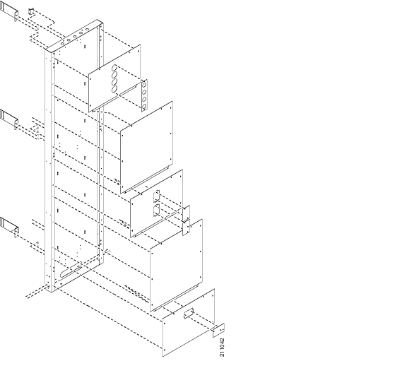
Cisco ONS 15454 Four-Shelf and Zero-Shelf Bay Assembly Overview
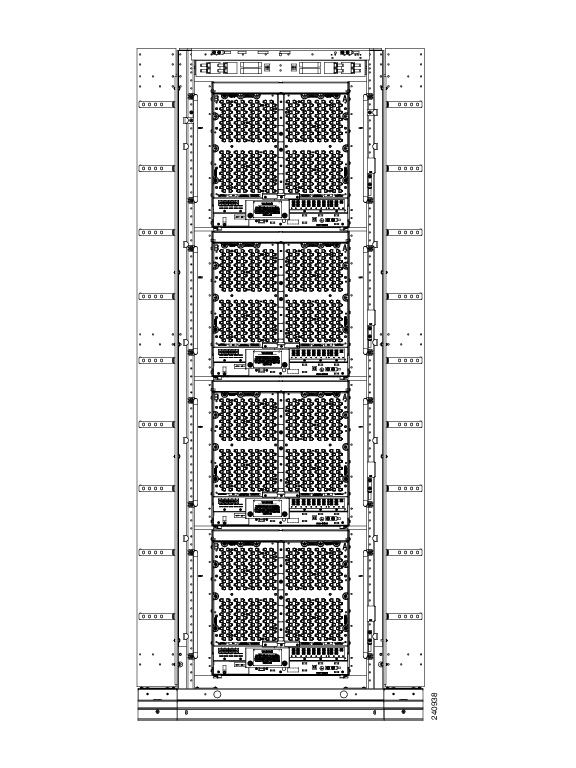
The Cisco ONS 15454 four-shelf and zero-shelf bay assemblies provide a dual-feed, prewired TPA-type fuse and alarm panel, two vertical fiber ducts, and two 5-inch (12.7-cm) vertical extenders and extender bases. The four-shelf bay assembly also provides a preinstalled, four-shelf configuration that includes four ONS 15454 shelf assemblies with electrical interface assembly (EIA) panels or EIA blank cover panels.
Figure 1 shows the rear view of a High-Density BNC EIA and Figure 2 shows the rear view of a MiniBNC EIA.
Figure 1 Rear View of High-Density BNC EIA
The ONS 15454 high-density BNC EIA supports 48 DS-3 circuits on each side of the ONS 15454 (48 transmit and 48 receive connectors). If you install BNC EIAs on both sides of the unit, the ONS 15454 hosts up to 96 circuits. The high-density BNC EIA supports Trompeter UCBJ224 (75-ohm) 4-leg connectors (King or ITT are also compatible). Use straight connectors on RG-59/U cable to connect to the high-density BNC EIA. Cisco recommends these cables for connection to a patch panel; they are designed for long runs. You can use high-density BNC EIAs for DS-3 (including the DS3XM-6 and DS3XM-12) or EC-1 cards. Figure 1 shows the rear view of a high-density BNC EIA.
Figure 2 Rear View of MiniBNC EIA
The ONS 15454 MiniBNC EIA supports a maximum of 192 transmit and receive DS-3 connections, 96 per side (A and B) through 192 miniBNC connectors on each side. If you install BNC EIAs on both sides of the unit, the ONS 15454 hosts up to 192 circuits. The MiniBNC EIAs are designed to support DS-3 and EC-1 signals. Figure 2 shows the rear view of a MiniBNC EIA.
The MiniBNC EIA supports the following cards:
•
DS3-12, DS3N-12
•
•
•
•
•
•
MiniBNCs support available high-density cards in unprotected and 1:N protection (where N < 2) protection groups.
For more information on High-Density BNC EIA and MiniBNC EIA, refer sections High-Density BNC EIA and MiniBNC EIA in Chapter 1, Shelf and Backplane Hardware in Cisco ONS 15454 Reference Manual.
Figure 3 Four-Shelf Bay Assembly
Caution
Note
Figure 4 shows how the rack is assembled.
Figure 4 Rack Assembly
Safety Recommendations
The following guidelines will help to ensure your safety and protect the equipment. This list does not include every potentially hazardous situation.
•
•
•
•
•
•
Included Material
The zero-shelf and four-shelf bay assemblies ship with the following materials:
•
•
•
•
•
•
•
•
•
•
•
In addition to the list above, the four-shelf bay assembly also ships with the following materials:
•
•
•
•
•
•
•
•
Recommended Material
Because most of the installation is complete when you receive the system, the bay assembly requires little installation material. The most significant tasks are removing the packaging from the bay assembly and removing the bay assembly from the shipping pallet. Because the actual installation of the bay assembly in each facility is done according to local site practice, your material needs may vary.
Cisco recommends that you have the following items on hand for installation:
•
•
•
•
•
•
•
Cisco ONS 15454-FAP-LVD Operations Guide.Unpacking Instructions
The ONS 15454 four-shelf and zero-shelf bay assembly ships in a corrugated container that covers the rack on its shipping pallet. After removing the corrugated container, you must remove the bolts that hold the rack to the pallet before moving the unit to the desired location. Figure 5 shows the four-shelf bay assembly on a shipping pallet.
Caution
Step 1
Step 2
Step 3
Step 4
Step 5
a.
b.
Step 6
Step 7
Figure 5 Four-Shelf Bay Assembly on a Shipping Pallet
Warning
Installation Instructions
Prior to installing the bay assembly, you should prepare your slab or raised floor plan.
Prepare the Slab Floor
Mark and drill your slab floor according to your slab floor plan.
Level Equipment
Temporarily position and level the equipment using metal shims and the equipment frame.
Drill Slab Floor
Step 1
Step 2
Step 3
Step 4
Step 5
Figure 6 Cross-Section of Rack Showing Cabling Routes (Slab for Local)
Figure 7 Slab Base Fiber Routing
Prepare the Raised Floor
If using a raised floor, mark and drill the floor according to your raised floor plan.
Level Equipment
The raised floor is laser-leveled at the time of the floor installation, so no leveling blocks or shims should be necessary to level the frames. This is especially important in seismic zones 2B and higher, because leveling blocks will cause a rocking motion of the frames during an earthquake.
Cut and Drill Removable Floor Tile
Step 1
•
•
•
•
Step 2
Step 3
Step 4
Step 5
Note
Note
Note
Figure 8 Raised Floor Cutout for CORE and Local
Framework Anchoring
To anchor framework to a raised floor, you must know the earthquake zone where the equipment is being installed. Zones 0 to 2A have the frames bolted to the raised floor through a U-channel across the bottom of the floor tile and stringers. Zones 2B to 4 have 1/2-inch threaded rods extending through the raised floor and connected to seismic anchors with coupling nuts. In all zones, standard hold-down parts are used on top of the floor with threaded rods of varying lengths. Anchors and hold-down material must be engineered for proper seismic zone.
Seismic Zones 0 to 2A
To fasten network and unequal flange duct framework to a raised floor:
Step 1
In the base of the frame, use the hold-down plate engineered for that frame, threaded rod, nut, washer, insulating bushing, and hold-down washer.
On the bottom of the U-channel, use the clip, washer, lockwasher, and nut.
Note
Warning
Step 2
Note
Seismic Zones 2B to 4
In seismic zones 2B and higher, threaded rods are run down to seismic anchors with coupling nuts from the concrete floor. U-channels are not used in higher earthquake zones. Anchor the rack at all four corners in higher earthquake zones.
Note
Install the ONS 15454 Four-Shelf or Zero-Shelf Bay Assembly
The emphasis in the following installation instructions is to position the bay assembly in your facility after it has been removed from its shipping pallet. Perform actual installation and individual node provisioning according to local site practice.
Step 1
Step 2
Step 3
Step 4
Step 5
Step 6
Step 7
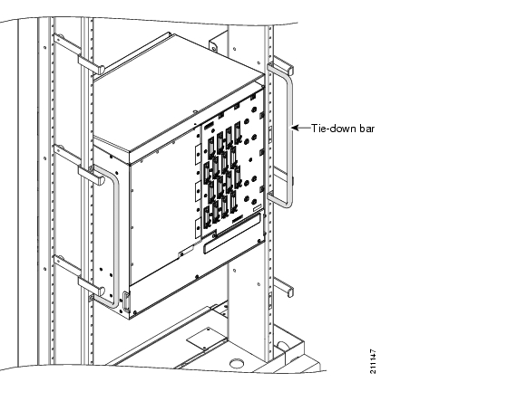
Install the Tie-Down Bar
Tie-down bars can be installed to secure cabling on the rear of the bay assembly rack. The tie-down bar can be used to provide a diverse path for redundant power feeds and cables. Up to eight tie-down bars can be installed in the four-shelf bay assembly rack, one on each side of each bay ( Figure 9).
Step 1
Step 2
Figure 9 Installing the Tie-Down Bar
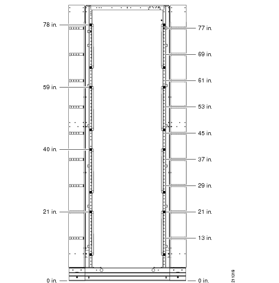
Tie-Down Bar and Fiber Bracket Locations
Figure 10 shows the proper location of the tie-down bars and fiber brackets on the rear of the bay assembly rack. Measuring the height in inches from the floor, the locations of the top screw hole on each tie-down bar are shown on the left side of the figure. The attachment points for the fiber brackets are shown on the right side of the figure.
Figure 10 Location of Tie-Down Bars and Fiber Brackets (Rear View of Rack)
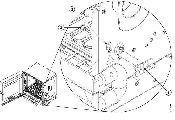
Attach the ESD Bracket
To provide electrostatic discharge (ESD) protection when handling cards, one ESD bracket can be attached to the side of each bay ( Figure 11). You can attach one per bay (up to four maximum) for ease of access.
Step 1
Step 2
Step 3
Figure 11 Attaching the ESD Bracket
Cabling Illustrations
Figure 12 through Figure 26 illustrate cabling schemes for a bay assembly.
Route Fiber from the Top
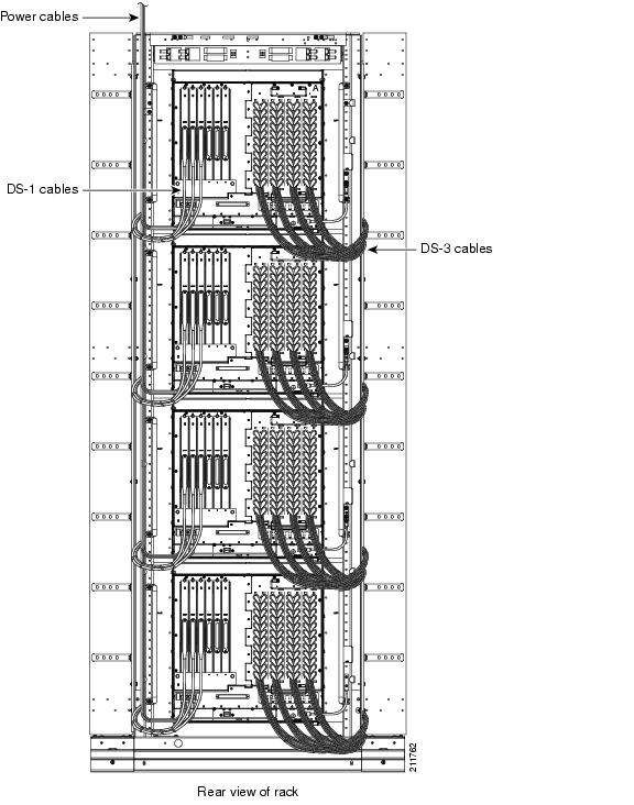
Fiber and power cables to each node are typically routed from the top of the rack, as shown in Figure 12 and Figure 13.
Figure 12 Routing Cables from the Top on a Four-Node Rack (Rear View)
Figure 13 Routing Cables from the Top on a Four-Node Rack (Side View)
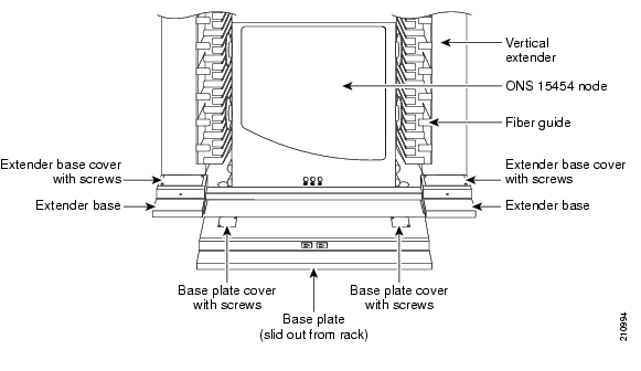
Route Fiber Through the Base
Cutouts in the extender base units at the bottom of the rack provide the option of routing cables from the raised floor tile through the bottom of the rack.
Step 1
Figure 14 Sliding the Base Plate Out from the Rack
Step 2
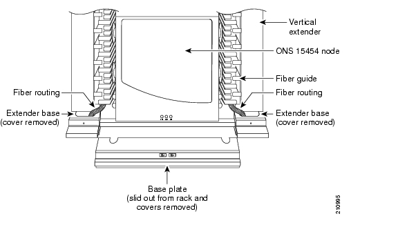
Figure 15 Base Plate and Extender Bases with Covers Removed
When the covers have been removed, you have access to the base of the rack and any holes previously cut into the raised floor tile, as shown in Figure 16.
Figure 16 Raised Floor Base Fiber Routing Close-up
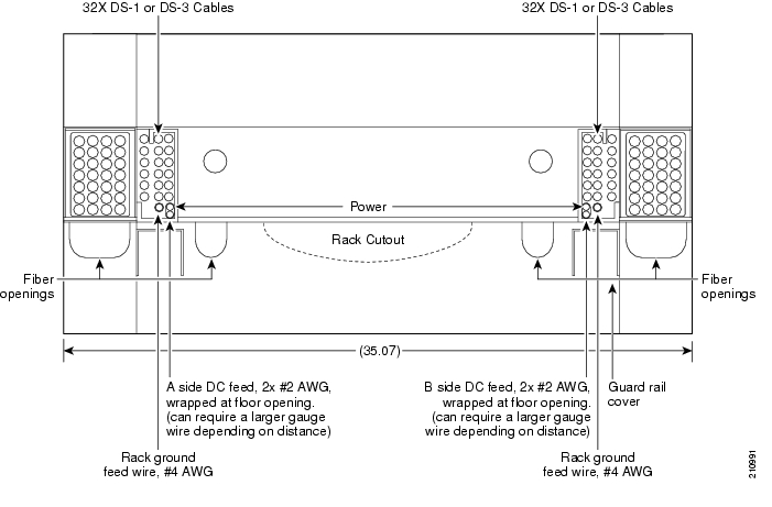
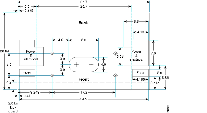
You can use the base plate or extender base holes to route the fibers. Cisco recommends using the base plate holes for the bottom node and the extender base holes for the other three nodes on the four-node rack. All electrical cables will be routed in the back of the rack in the extender bases. Holes should already be cut out in the raised floor tile to compensate for any DS-1, DS-3, ground, and power cables.
Step 3
Figure 17 Raised Floor Base Fiber Routing
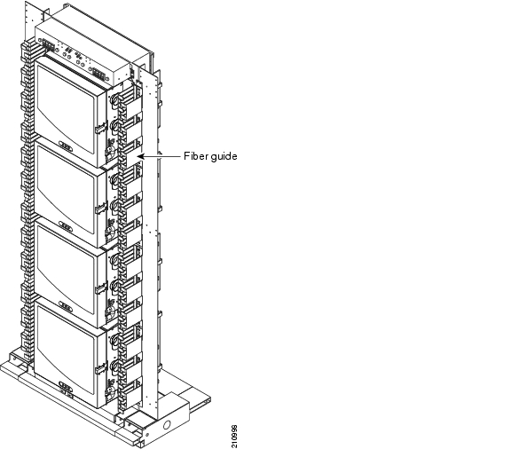
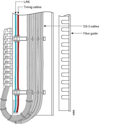
Figure 18 Fiber Guide on a Four-Node Rack
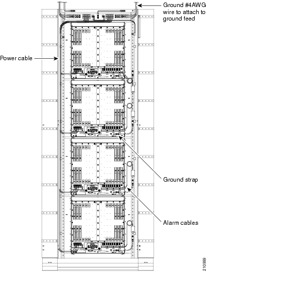
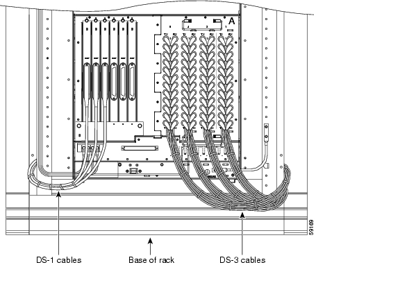
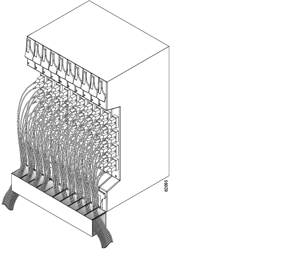
Figure 19 Rear View of a Four-Node Rack
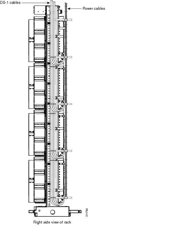
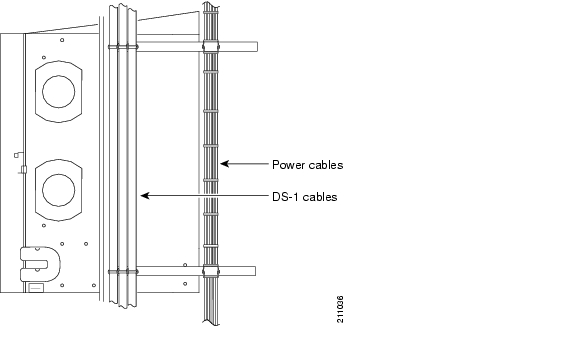
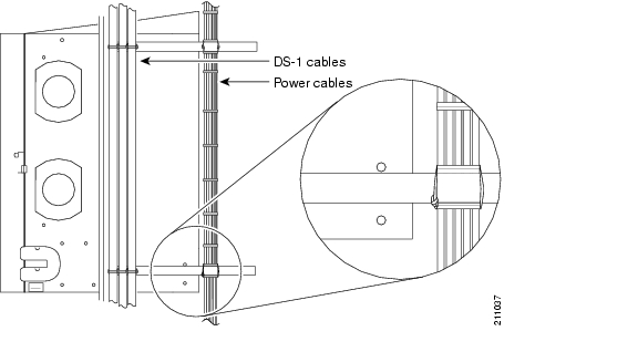
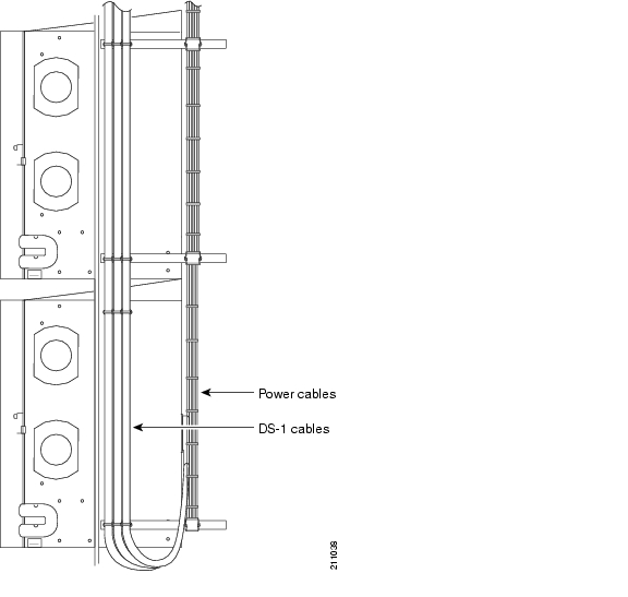
Figure 20 Side View of DS-1 and Power Cables
Figure 21 Close-Up of Power Cable Lacing
Figure 22 Side Rack View of DS-1 and Power Cables
Figure 23 Cabling on One Node
Figure 24 Standoff with Wiring
Figure 25 Standoff at Bottom of Rack
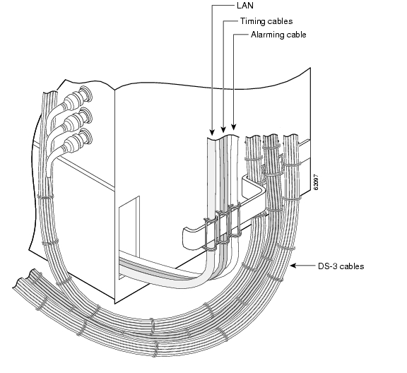
Figure 26 48 Fibers from One Node
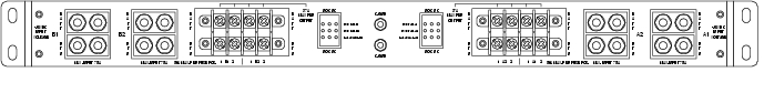
Fuse and Alarm Panel Wiring
The Fuse and Alarm Panel (FAP) included in the four-shelf and zero-shelf bay assemblies provides four sets of two 30-A fused drops, for powering the redundant A and B inputs of four ONS 15454 nodes. The FAP has integrated low voltage disconnect (LVD) circuitry to provide a shutdown of the output power due to a drop in input voltage from the network power source.
Necessary overload protection is provided with eight user pluggable TPA fuses, separated into two sets of four fuses, to allow for diverse routing of two power sources to each shelf assembly. Also provided is an LED alarm display for visual fault identification, with the capability for external alarm closures for remote fault signaling.
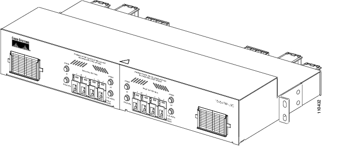
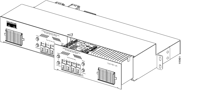
The FAP has the capability to report six alarms to a network operations center (NOC). Equipped with an alarm interface card, the ONS 15454 has the capability to report up to 32 environmental alarms, depending on which alarm interface card is installed. Only one shelf (with an AIC/AIC-I card) is needed to monitor alarming for a loss of power and a blown fuse condition. The alarms are reported to the NOC through the connected LAN wire also tied to the same shelf. Figure 27 through Figure 30 show different views of the FAP including front, rear, Side A, Side B, and alarming. Refer to the latest release of the Cisco ONS 15454-FAP-LVD Operations Guide for more information on the fuse and alarm panel.
Figure 27 FAP (Front View)
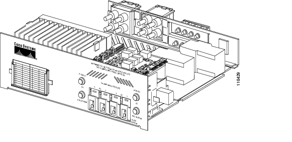
Figure 28 FAP Side A
Figure 29 FAP Side B
Figure 30 FAP (Rear View)
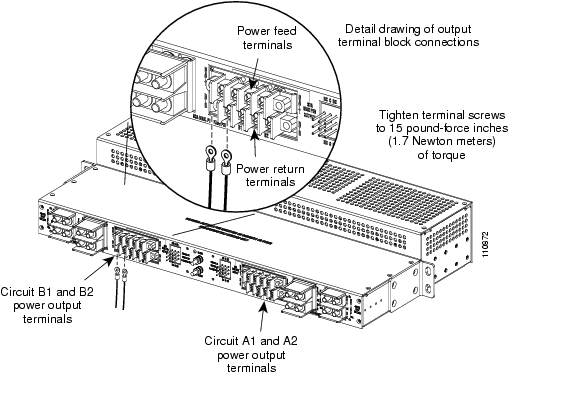
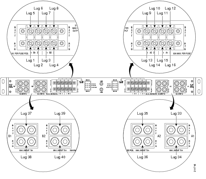
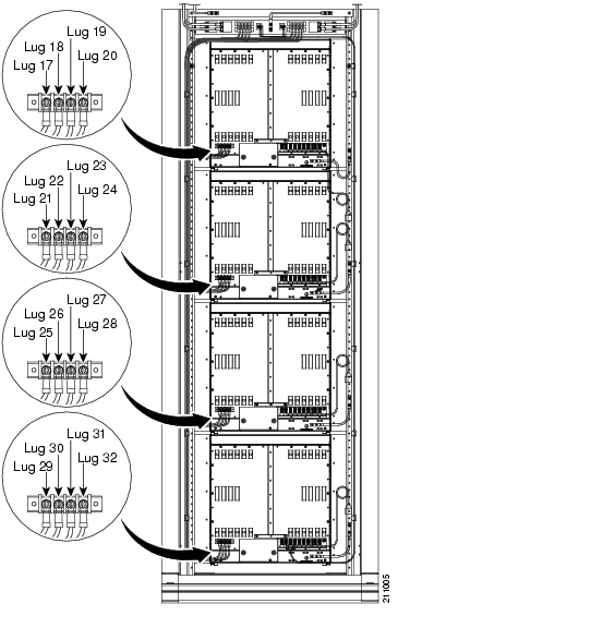
FAP Output and Input Power
Route output and input power according to local site practice. Refer to the latest release of the
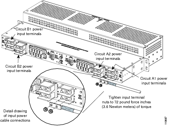
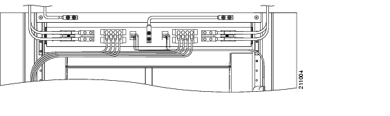
Cisco ONS 15454-FAP-LVD Operations Guide for more information. Figure 31 through Figure 35 show output and input lugs and wiring and Table 1 lists lug wiring positions.
Note
Figure 31 Connecting Output Power Using Ring-Type Compression Lugs
Figure 32 Close-Up of Lugs on Rear of FAP
Figure 33 Lug Wiring from Rear of FAP to Shelf Lugs
Figure 34 Connecting Input Power
Figure 35 Wiring from Rear of FAP
Replace Side A or Side B of the FAP
Note
Step 1
Warning
Step 2
Step 3
Step 4
Step 5
Figure 36 Removing or Replacing FAP Side B
Step 6
Step 7
Step 8
Step 9
Ground and Power
The ground studs and power input and output terminals are mounted on the rear side of the FAP. The plastic protective covers install over the input and output power terminals to prevent accidental contact with the terminals when power is present in the panel.
Warning
Warning
Warning
Warning
Warning
Warning
Warning
Caution
Central Office Ground to Bay Wire Ground
Connect the common central office (CO) ground to the bay wire ground according to local site practice.
Note
Central Office Power to FAP
Connect the CO power to the FAP according to local site practice.
Note
Optional Kits
There are four optional kits that can be ordered separately as needed for cable protection, aisle guards, and supplementary installation components. This section lists the kits by title and provides descriptions for each kit.
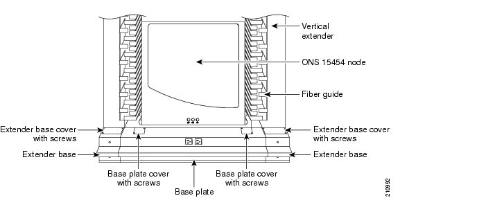
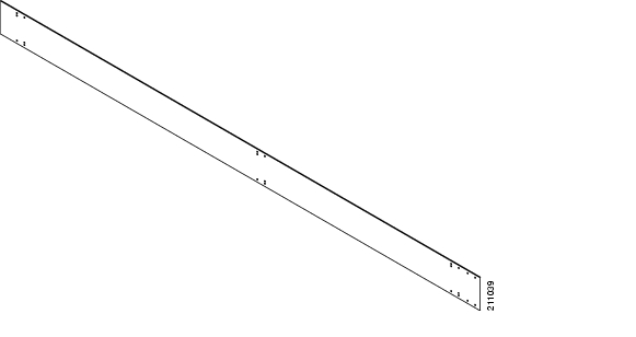
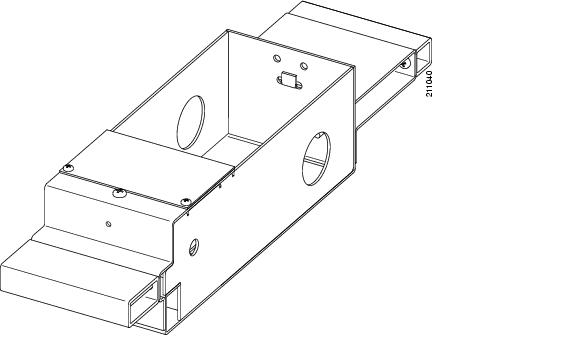
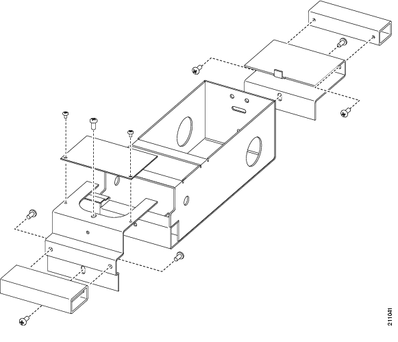
ONS 15454 Bay Extender Kit (5-inch)
The ONS 15454 Bay Extender Kit provides rear cable protection and additional cable management space. It includes a 5-inch (12.7-cm) vertical extender ( Figure 37) and extender base ( Figure 38 and Figure 39).
Figure 37 Vertical Extender
Figure 38 Extender Base
Figure 39 Extender Base Assembly
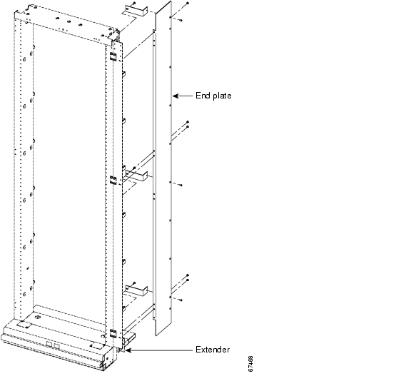
ONS 15454 Bay End Plate Cover Kit
The ONS 15454 Bay End Plate Cover Kit provides a basic end plate for temporary cable protection. It contains parts that mount flush against the rack with no major footprint change (thickness of the metal only) against the edge of the rack to protect the cables. This plate is usually used for an aisle that is not complete, or as an aisle guard for aisles. The end plate cover can be mounted with the vertical extender as shown in Figure 40 or mounted directly as shown in Figure 41.
Figure 40 End Plate Cover Assembly Mounted with Extender
Figure 41 End Plate Cover Assembly Mounted Directly
ONS 15454 Bay End Guard Kit
The ONS 15454 Bay End Guard Kit provides a full aisle guard with AC on/off switch cutout. It is used to complete the end of the aisle (about 2.50-inch (6.35-cm) wide or thick). The end guard may or may not have power (110 VAC), 110 VAC outlets, and a visual light for alarms. See Figure 42 for end guard components.
Figure 42 End Guard Assembly
ONS 15454 First Aid Kit
The ONS 15454 First Aid Kit contains extra items such as tape, cord, tags, and cosmetic items such as touch-up paint to promote a quality installation.
This document is to be used in conjunction with Cisco ONS 15454 user documentation and 15454-FAP-LVD documentation.
Copyright © 2007, Cisco Systems, Inc.
All rights reserved.
![]()
![]()
![]()
![]()
![]()
![]()
![]()
![]()
Posted: Tue Oct 9 23:56:28 PDT 2007
All contents are Copyright © 1992--2007 Cisco Systems, Inc. All rights reserved.
Important Notices and Privacy Statement.