Table Of Contents
Performance Monitoring
8.1 Using the Performance Monitoring Screen
8.1.1 Viewing PMs
8.1.2 Changing the Screen Intervals
8.1.3 Viewing Near End and Far End PMs
8.1.4 Using the Signal-Type Menu
8.1.5 Using the Baseline Button
8.1.6 Using the Clear Button
8.2 Changing Thresholds
8.3 Enabling Intermediate-Path Performance Monitoring
8.4 Pointer Justification Count Parameters
8.5 Performance Monitoring for Electrical Cards
8.5.1 EC1 Card Performance Monitoring Parameters
8.5.2 DS1 and DS1N Card Performance Monitoring Parameters
8.5.3 DS3 and DS3N Card Performance Monitoring Parameters
8.5.4 DS3-12E and DS3N-12E Card Performance Monitoring Parameters
8.5.5 DS3XM-6 Card Performance Monitoring Parameters
8.6 Performance Monitoring for Optical Cards
8.6.1 OC-3 Card Performance Monitoring Parameters
8.6.2 OC-12, OC-48, and OC-192 Card Performance Monitoring Parameters
Performance Monitoring
Performance monitoring parameters (PMs) are used by service providers to gather, store, threshold, and report performance data for early detection of problems. PM terms are defined for both electrical cards and optical cards.
This chapter provides the:
• "Using the Performance Monitoring Screen" section
• "Changing Thresholds" section
• "Enabling Intermediate-Path Performance Monitoring" section
• "Pointer Justification Count Parameters" section
• "Performance Monitoring for Electrical Cards" section
• "Performance Monitoring for Optical Cards" section
For information about:
•Ethernet PMs, see Chapter 9, "Ethernet Operation"
•Troubleshooting UPSR switch counts, see the alarm troubleshooting information in the Cisco ONS 15454 Troubleshooting and Reference Guide, Release 3.1
•Editing UPSR circuits, see Chapter 6, "Circuits and Tunnels."
•Digital transmission surveillance, see Telcordia's GR-1230-CORE, GR-820-CORE, and GR-253-CORE documents and the ANSI document entitled Digital Hierarchy - Layer 1 In-Service Digital Transmission Performance Monitoring
8.1 Using the Performance Monitoring Screen
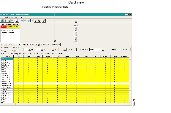
The following sections describe how to use basic screen elements such as tabs, menus, and informational columns. Figure 8-1 shows the Performance tab of Cisco Transport Controller (CTC) card-level view.
Figure 8-1 Viewing performance monitoring information
8.1.1 Viewing PMs
Before you view PMs, be sure you have created the appropriate circuits and provisioned the card according to your specifications. For information about circuit creation and card provisioning, see the Cisco ONS 15454 Installation and Operations Guide.
Procedure: View PMs
Step 1 Open the electrical or optical card of choice. Double-click the card's graphic in the main (node) view or right-click the card and select Open Card. (Clicking a card once highlights the card only.)
Step 2 From the card view, click the Performance tab.
Step 3 View the PM parameter names that appear on the left portion of the screen in the Param column. The parameter numbers appear on the right portion of the screen in the Curr (current), and Prev (previous) columns.
8.1.2 Changing the Screen Intervals
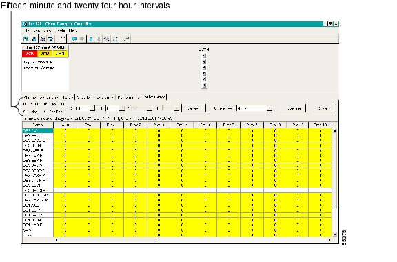
Changing the screen view allows you to view PMs in 15-minute intervals or 24-hour periods. Figure 8-2 shows the time interval buttons on the Performance Monitoring screen.
Figure 8-2 Time interval buttons on the card view Performance tab
Procedure: Select Fifteen-Minute PM Intervals on the Performance Monitoring Screen
Step 1 Open the electrical or optical card of choice. Double-click the card's graphic in the main (node) view or right-click the card and select Open Card. (Clicking a card once highlights the card only.)
Step 2 From the card view, click the Performance tab.
Step 3 Click the 15 min button.
Step 4 Click the Refresh button. Performance monitoring parameters display in 15-minute intervals synchronized with the time of day.
Step 5 View the Current column to find PM counts for the current 15-minute interval.
Each monitored performance parameter has corresponding threshold values for the current time period. If the value of the counter exceeds the threshold value for a particular 15-minute interval, a threshold crossing alert (TCA) will be raised. The value represents the counter for each specific performance monitoring parameter.
Step 6 View the Prev-N columns to find PM counts for the preceding 15-minute intervals.
Note If a complete 15-minute interval count is not possible, the value displays with a yellow background. An incomplete or incorrect count can be caused by changing node timing settings, changing the time zone settings on CTC, replacing a card, resetting a card, changing port states, or by using the Baseline button. When a complete count occurs, the subsequent 15-minute interval appears with a white background.
Procedure: Select Twenty-Four Hour PM Intervals on the Performance Monitoring Screen
Step 1 Open the electrical or optical card of choice. Double-click the card's graphic in the main (node) view or right-click the card and select Open Card. (Clicking a card once highlights the card only.)
Step 2 From the card view, click the Performance tab.
Step 3 Click the 1 day button.
Step 4 Click the Refresh button. Performance monitoring displays in 24-hour periods synchronized with the time of day.
Step 5 View the Current column to find PM counts for the current 24-hour period.
Each monitored performance parameter has corresponding threshold values for the current time period. If the value of the counter exceeds the threshold value for a particular 24-hour period, a threshold crossing alert (TCA) will be raised. The value represents the counter for each specific performance monitoring parameter.
Step 6 View the Prev columns to find PM counts for the preceding 24-hour period.
Note If a complete count over a 24-hour period is not possible, the value displays with a yellow background. An incomplete or incorrect count can be caused by changing node timing settings, changing the time zone settings on CTC, replacing a card, resetting a card, changing port states, or by using the Baseline button. When a complete count occurs, the subsequent 24-hour period appears with a white background.
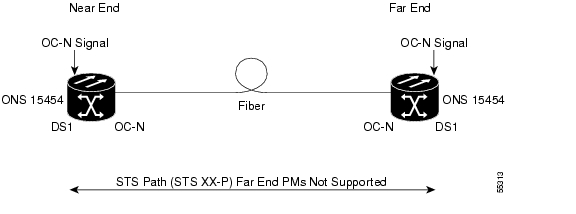
8.1.3 Viewing Near End and Far End PMs
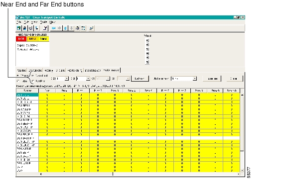
Select the Near End or Far End button depending on the PMs you wish to view. Only cards that allow both near-end and far-end monitoring have these buttons as an option. Figure 8-3 shows the Near End and Far End buttons on the Performance Monitoring screen.
Figure 8-3 Near End and Far End buttons on the card view Performance tab
Procedure: Select Near End PMs on the Performance Monitoring Screen
Step 1 Open the electrical or optical card of choice. Double-click the card's graphic in the main (node) view or right-click the card and select Open Card. (Clicking a card once highlights the card only.)
Step 2 From the card view, click the Performance tab.
Step 3 Click the Near End button.
Step 4 Click the Refresh button. All PMs occurring for the selected card on the incoming signal are displayed.
Procedure: Select Far End PMs on the Performance Monitoring Screen
Step 1 Open the electrical or optical card of choice. To do so, double-click the card's graphic in the main (node) view or right-click the card and select Open Card. (Clicking a card once highlights the card only.)
Step 2 From the card view, click the Performance tab.
Step 3 Click the Far End button.
Step 4 Click the Refresh button. All PMs recorded by the far-end node for the selected card on the outgoing signal are displayed.
8.1.4 Using the Signal-Type Menu
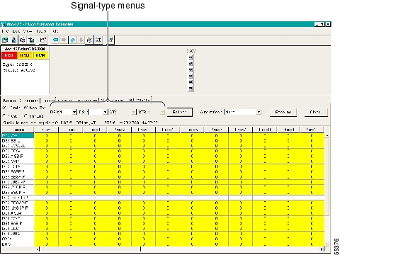
Use the signal-type menus to monitor PMs for near-end or far-end signals on a selected port. Different signal-type menus appear depending on the card type and the circuit type. The appropriate types (DS1, DS3, VT path, STS path, OCn section, line) appear based on the card. For example, the DS3XM has DS3, DS1, VT path, and STS path PMs. Figure 8-4 shows the signal-type menus on the Performance Monitoring screen for a DS3XM-6 card.
Figure 8-4 Signal-type menus for a DS3XM-6 card
Procedure: Select Signal-Type Menus on the Performance Monitoring Screen
Step 1 Open the electrical or optical card of choice. Double-click the card's graphic in the main (node) view or right-click the card and select Open Card. (Clicking a card once highlights the card only.)
Step 2 From the card view, click the Performance tab.
Step 3 Click the signal-type menu. (For example, the DS3XM card has menus labeled DS3, DS1, VT, and STS.)
Step 4 Select a port using the signal-type menu.
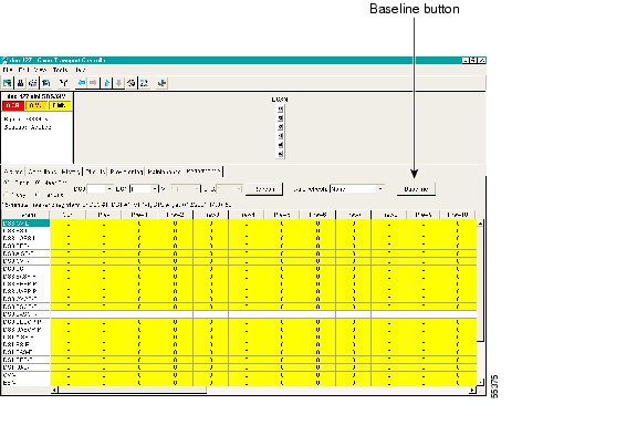
8.1.5 Using the Baseline Button
In Software R3.0 and higher, the Baseline button located on the far right of the screen clears the PM count displayed in the Current column, but does not clear the PM count on the card. When the current 15-minute or 24-hour time interval expires or the screen view changes, the total number of PM counts on the card and on the screen appear in the appropriate column.
The baseline values are discarded if you change views to a different screen and then return to the Performance Monitoring screen. The Baseline button enables you to easily see how quickly PM counts are rising without having to perform calculations. Figure 8-5 shows the Baseline button on the Performance Monitoring screen.
Figure 8-5 Baseline button for clearing displayed PM counts
Procedure: Use the Baseline Button on the Performance Monitoring Screen
Step 1 Open the electrical or optical card of choice. Double-click the card's graphic in the main (node) view or right-click the card and select Open Card. (Clicking a card once highlights the card only.)
Step 2 From the card view, click the Performance tab.
Step 3 Click the Baseline button.
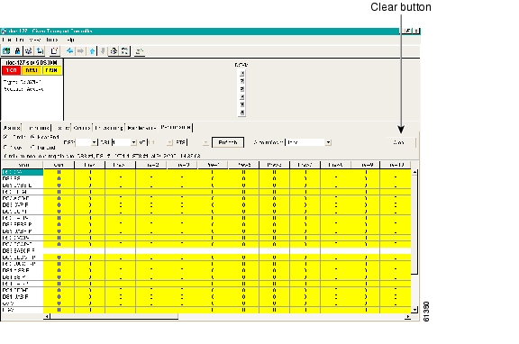
8.1.6 Using the Clear Button
The Clear button located on the far right of the Performance Monitoring screen clears certain PM counts depending on the option selected. Figure 8-6 shows the Clear button on the Performance Monitoring screen.
Caution Pressing the Clear button can potentially mask problems if used incorrectly. This button is commonly used for testing purposes.
Figure 8-6 Clear button for clearing PM counts
Procedure: Use the Clear Button on the Performance Monitoring Screen
Step 1 Open the electrical or optical card of choice. Double-click the card's graphic in the main (node) view or right-click the card and select Open Card. (Clicking a card once highlights the card only.)
Step 2 From the card view, click the Performance tab.
Step 3 Click the Clear button.
Step 4 From the Clear Statistics menu, choose one of three options:
•Selected Interfaces: Clearing selected interfaces erases all PM counts associated with the selected radio buttons. For example, if the 15 min and the Near End buttons are selected and you click the Clear button, all near-end PM counts in the current 15-minute interval are erased from the card and the screen display.
•All interfaces on port x: Clearing all interfaces on port x erases from the card and the screen display all PM counts associated with all combinations of the radio buttons on the selected port. This means the 15-minute near-end and far-end counts are cleared, and 24-hour near-end and far-end counts are cleared from the card and the screen display.
•All interfaces on card: Clearing all interfaces on the card erases from the card and the screen display all PM counts for data and ports on all interfaces.
Step 5 From the Zero Data menu, click Yes to clear the selected statistics.
Note The Ethernet cards are the only cards without the Clear button option.
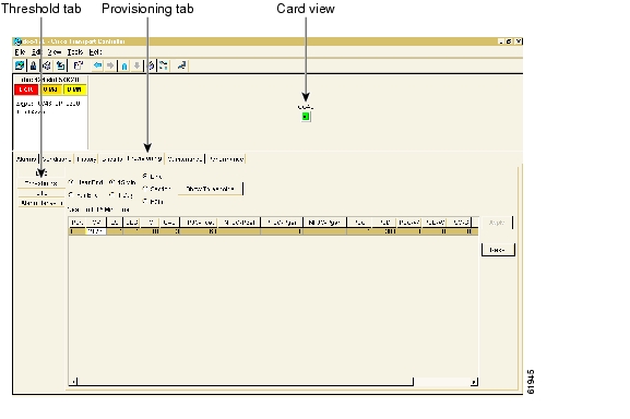
8.2 Changing Thresholds
Thresholds are used to set error levels for each PM. You can program PM threshold ranges from the Provisioning > Threshold tabs on the card view. For procedures on provisioning card thresholds, such as line, path, and SONET thresholds, see Chapter 7, "Card Provisioning."
During the accumulation cycle, if the current value of a performance monitoring parameter reaches or exceeds its corresponding threshold value, a threshold crossing alert (TCA) is generated by the node and sent to CTC. TCAs provide early detection of performance degradation. When a threshold is crossed, the node continues to count the errors during a given accumulation period. If 0 is entered as the threshold value, the performance monitoring parameter is disabled. Figure 8-7 shows the Provisioning > Threshold tabs for an OC-48 card.
Figure 8-7 Threshold tab for setting threshold values
Change the threshold if the default value does not satisfy your error monitoring needs. For example, customers with a critical DS1 installed for 911 calls must guarantee the best quality of service on the line; therefore, they lower all thresholds so that the slightest error raises a TCA.
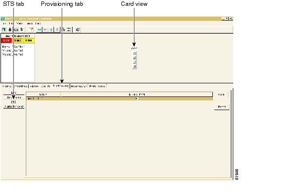
8.3 Enabling Intermediate-Path Performance Monitoring
Intermediate-path performance monitoring (IPPM) allows transparent monitoring of a constituent channel of an incoming transmission signal by a node that does not terminate that channel. Many large ONS 15454 networks only use line terminating equipment (LTE) not path terminating equipment (PTE). Table 8-1 shows ONS 15454 cards that are considered LTEs. Figure 8-8 shows the Provisioning > STS tabs for an OC-3 card.
Table 8-1 Traffic Cards That Terminate the Line, Called LTEs
Line Terminating Equipment
|
EC1-12
|
OC3 IR 4/STM1 SH 1310
|
OC12 IR/STM4 SH 1310
|
OC12 LR/STM4 LH 1310
|
OC12 LR/STM4 LH 1550
|
OC48 IR 1310
|
OC48 LR 1550
|
OC48 IR/STM16 SH AS 1310
|
OC48 LR/STM16 LH AS 1550
|
OC48 ELR/STM16 EH 100 GHz
|
OC48 ELR/STM16 EH 200 GHz
|
OC192 LR/STM64 LH 1550
|
Figure 8-8 STS tab for enabling IPPM
Software R3.0 and higher allows LTE cards to monitor near-end PM data on individual STS payloads by enabling IPPM. After enabling IPPM provisioning on the line card, service providers can monitor large amounts of STS traffic through intermediate nodes, thus making troubleshooting and maintenance activities more efficient.
IPPM occurs only on STS paths which have IPPM enabled, and TCAs are raised only for PM parameters on the selected IPPM paths. The monitored IPPMs are STS CV-P, STS ES-P, STS SES-P, STS UAS-P, and STS FC-P. For detailed information about provisioning cards and the procedure for enabling IPPM, see Chapter 7, "Card Provisioning."
Note The far-end IPPM feature is not supported in Software R3.1. However, SONET path PMs can be monitored by logging into the far-end node directly.
The ONS 15454 performs IPPM by examining the overhead in the monitored path and by reading all of the near-end path PMs in the incoming direction of transmission. The IPPM process allows the path signal to pass bidirectionally through the node completely unaltered.
For detailed information about specific PMs, locate the card name in the following sections and review the appropriate definition.
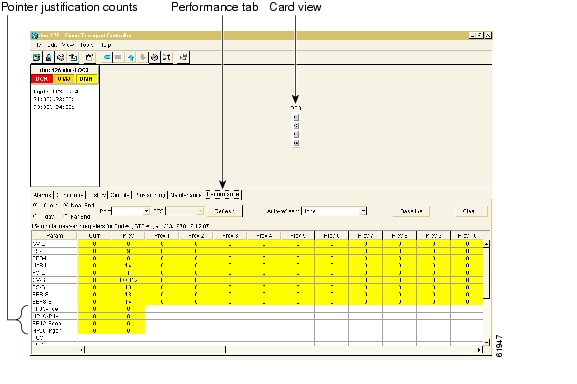
8.4 Pointer Justification Count Parameters
Pointers are used to compensate for frequency and phase variations. Pointer justification counts indicate timing errors on SONET networks. There are positive (PPJC) and negative (NPJC) pointer justification count parameters. PPJC is a count of path-detected (PPJC-Pdet) or path-generated (PPJC-Pgen) positive pointer justifications. NPJC is a count of path-detected (NPJC-Pdet) or path-generated (NPJC-Pgen) negative pointer justifications depending on the specific PM name.
Figure 8-9 shows pointer justification count parameters on the Performance Monitoring screen. You can enable PPJC and NPJC performance monitoring parameters for LTE cards. See Table 8-1 for a list of Cisco ONS 15454 LTE cards.
For pointer justification count definitions, see the "EC1 Card Performance Monitoring Parameters" section, the "OC-3 Card Performance Monitoring Parameters" section, or the "OC-12, OC-48, and OC-192 Card Performance Monitoring Parameters" section depending on the cards in use.
Figure 8-9 Viewing pointer justification count parameters
Pointers provide a way to align the phase variations in STS and VT payloads. The STS payload pointer is located in the H1 and H2 bytes of the line overhead. Clocking differences are measured by the offset in bytes from the pointer to the first byte of the STS synchronous payload envelope (SPE) called the J1 byte. Clocking differences that exceed the normal range of 0 to 782 can cause data loss.
A consistent pointer justification count indicates clock synchronization problems between nodes. Detected and generated counts should be equal. A difference between the counts means the node transmitting the original pointer justification has timing variations with the node detecting and transmitting this count. Positive pointer adjustments occur when the frame rate of the SPE is too slow in relation to the rate of the STS 1.
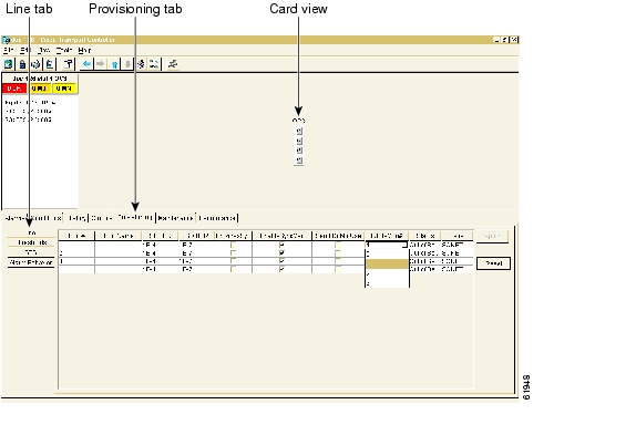
On CTC, the count fields for PPJC and NPJC PMs appear white and blank unless they are enabled on the Provisioning > Line tabs. Figure 8-10 shows the PJStsMon# menu on the Provisioning screen.
Figure 8-10 Line tab for enabling pointer justification count parameters
Procedure: Enable Pointer Justification Count Performance Monitoring
Step 1 Open the electrical or optical card of choice. Double-click the card's graphic in the main (node) view or right-click the card and select Open Card. (Clicking a card once highlights the card only.)
Step 2 From the card view, click the Provisioning > Line tabs.
Step 3 Click the PJStsMon# menu and select a number.
•The value of 0 means pointer justification monitoring is disabled.
•The values 1-N are the STS numbers on one port. One STS per port can be enabled from the PJStsMon# menu.
EC1 PJStsMon# card menu: 0 or 1 can be selected on a total of 12 ports.
OC-3 PJStsMon# card menu: 1, 2, or 3 can be selected on a total of 4 ports.
OC-12 PJStsMon# card menu: 1 or any number through 12 can be selected on 1 port.
OC-48 PJStsMon# card menu: 1 or any number through 48 can be selected on 1 port.
OC-192 PJStsMon# card menu: 1 or any number through 192 can be selected on 1 port.
Step 4 Click Apply and return to the Performance tab to view PM parameters.
8.5 Performance Monitoring for Electrical Cards
The following sections define performance monitoring parameters for the EC1, DS1, DS1N, DS3, DS3N, DS3-12E, DS3N-12E, and DS3XM electrical cards.
8.5.1 EC1 Card Performance Monitoring Parameters
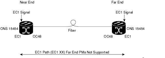
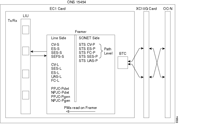
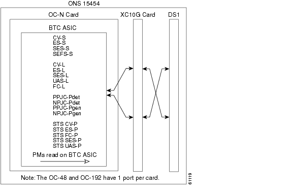
Figure 8-11 shows signal types that support far-end PMs. Far-end performance monitoring is not reported for EC1. Figure 8-12 shows where overhead bytes detected on the application specific integrated circuits (ASICs) produce performance monitoring parameters for the EC1 card.
Figure 8-11 Monitored signal types for the EC1 card
Note The XX in the illustration above represents all PMs listed below with the given prefix and/or suffix.
Figure 8-12 PM read points on the EC1 card
Note SONET path PMs will not count unless IPPM is enabled. For additional information, see the "Enable Intermediate-Path Performance Monitoring" procedure on page 7-25. The far-end IPPM feature is not supported in Software R3.1. However, SONET path PMs can be monitored by logging into the far-end node directly.
Table 8-2 Near-End Section PMs for the EC1 Card
Parameter
|
Definition
|
CV-S
|
Section Coding Violation (CV-S) is a count of BIP errors detected at the section-layer (i.e. using the B1 byte in the incoming SONET signal). Up to eight section BIP errors can be detected per STS-N frame; each error increments the current CV-S second register.
|
ES-S
|
Section Errored Seconds (ES-S) is a count of the number of seconds when at least one section-layer BIP error was detected or an SEF or loss of signal (LOS) defect was present.
|
SES-S
|
Section Severely Errored Seconds (SES-S) is a count of the seconds when K (see GR-253-CORE for value) or more section-layer BIP errors were detected or a severely errored frame (SEF) or LOS defect was present.
|
SEFS-S
|
Section Severely Errored Framing Seconds (SEFS-S) is a count of the seconds when an SEF defect was present. An SEF defect is expected during most seconds where an LOS or loss of frame (LOF) defect is present. However, there may be situations when that is not the case, and the SEFS-S parameter is only incremented based on the presence of the SEF defect.
|
Table 8-3 Near-End Line Layer PMs for the EC1 Card
Parameter
|
Definition
|
CV-L
|
Near-End Line Code Violation (CV-L) is a count of BIP errors detected at the line-layer (i.e. using the B2 bytes in the incoming SONET signal). Up to 8 x N BIP errors can be detected per STS-N frame, with each error incrementing the current CV-L second register.
|
ES-L
|
Near-End Line Errored Seconds (ES-L) is a count of the seconds when at least one line-layer BIP error was detected or an alarm indication signal-line (AIS-L) defect was present.
|
SES-L
|
Near-End Line Severely Errored Seconds (SES-L) is a count of the seconds when K (see GR-253 for values) or more line-layer BIP errors were detected or an AIS-L defect was present.
|
UAS-L
|
Near-End Line Unavailable Seconds (UAS-L) is a count of the seconds when the line is unavailable. A line becomes unavailable when ten consecutive seconds occur that qualify as SES-Ls, and the line continues to be unavailable until ten consecutive seconds occur that do not qualify as SES-Ls.
|
FC-L
|
Near-End Line Failure Count (FC-L) is a count of the number of near-end line failure events. A failure event begins when an AIS-L failure or a lower-layer, traffic-related, near-end failure is declared. This failure event ends when the failure is cleared. A failure event that begins in one period and ends in another period is counted only in the period where it begins.
|
Table 8-4 Near-End SONET Path PMs for the EC1 Card
Parameter
|
Definition
|
Note SONET path PMs will not count unless IPPM is enabled. For additional information, see the "Enable Intermediate-Path Performance Monitoring" procedure on page 7-25. The far-end IPPM feature is not supported in Software R3.1. However, SONET path PMs can be monitored by logging into the far-end node directly.
|
STS CV-P
|
Near-End STS Path Coding Violations (CV-P) is a count of BIP errors detected at the STS path layer (i.e., using the B3 byte). Up to eight BIP errors can be detected per frame; each error increments the current CV-P second register.
|
STS ES-P
|
Near-End STS Path Errored Seconds (ES-P) is a count of the seconds when at least one STS path BIP error was detected. STS ES-P can also be caused by an AIS-P defect (or a lower-layer, traffic-related, near-end defect) or an LOP-P defect.
|
STS FC-P
|
Near-End STS Path Failure Counts (FC-P) is a count of the number of near-end STS path failure events. A failure event begins when an AIS-P failure, an LOP-P failure, a unequipped path (UNEQ-P) or a trace identifier mismatch (TIM-P) failure is declared. A failure event also begins if the STS PTE monitoring the path supports ERDI-P for that path. The failure event ends when these failures are cleared.
|
STS SES-P
|
Near-End STS Path Severely Errored Seconds (SES-P) is a count of the seconds when K (2400) or more STS path BIP errors were detected. STS SES-P can also be caused by an AIS-P defect (or a lower-layer, traffic-related, near-end defect) or an LOP-P defect.
|
STS UAS-P
|
Near-End STS Path Unavailable Seconds (UAS-P) is a count of the seconds when the STS path was unavailable. An STS path becomes unavailable when ten consecutive seconds occur that qualify as SES-Ps, and it continues to be unavailable until ten consecutive seconds occur that do not qualify as SES-Ps.
|
Table 8-5 Near-End SONET Path BIP PMs for the EC1 Card
Parameter
|
Definition
|
PPJC-Pdet
|
Positive Pointer Justification Count, STS Path Detected (PPJC-Pdet) is a count of the positive pointer justifications detected on a particular path in an incoming SONET signal.
|
NPJC-Pdet
|
Negative Pointer Justification Count, STS Path Detected (NPJC-Pdet) is a count of the negative pointer justifications detected on a particular path in an incoming SONET signal.
|
PPJC-Pgen
|
Positive Pointer Justification Count, STS Path Generated (PPJC-Pgen) is a count of the positive pointer justifications generated for a particular path to reconcile the frequency of the SPE with the local clock.
|
NPJC-Pgen
|
Negative Pointer Justification Count, STS Path Generated (NPJC-Pgen) is a count of the negative pointer justifications generated for a particular path to reconcile the frequency of the synchronous payload envelope (SPE) with the local clock.
|
Table 8-6 Far-End Line Layer PMs for the EC-1 Card
Parameter
|
Definition
|
CV-L
|
Far-End Line Code Violation (CV-L) is a count of BIP errors detected by the far-end line terminating equipment (LTE) and reported back to the near-end LTE using the REI-L indication in the line overhead. For SONET signals at rates below OC-48, up to 8 x N BIP errors per STS-N frame can be indicated using the REI-L. For OC-48 signals, up to 255 BIP errors per STS-N frame can be indicated. The current CV-L second register is incremented for each BIP error indicated by the incoming REI-L.
|
ES-L
|
Far-End Line Errored Seconds (ES-L) is a count of the seconds when at least one line-layer BIP error was reported by the far-end LTE or an RDI-L defect was present.
|
SES-L
|
Far-End Line Severely Errored Seconds (SES-L) is a count of the seconds when K (see GR-253-CORE for values) or more line-layer BIP errors were reported by the far-end LTE or an RDI-L defect was present.
|
UAS-L
|
Far-End Line Unavailable Seconds (UAS-L) is a count of the seconds when the line is unavailable at the far end. A line becomes unavailable at the far end when ten consecutive seconds occur that qualify as SES-LFEs and it continues to be unavailable until ten consecutive seconds occur that do not qualify as SES-LFEs.
|
FC-L
|
Far-End Line Failure Count (FC-L) is a count of the number of far-end line failure events. A failure event begins when RFI-L failure is declared, and it ends when the RFI-L failure clears. A failure event that begins in one period and ends in another period is counted only in the period where it began.
|
8.5.2 DS1 and DS1N Card Performance Monitoring Parameters
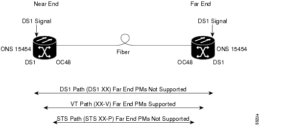
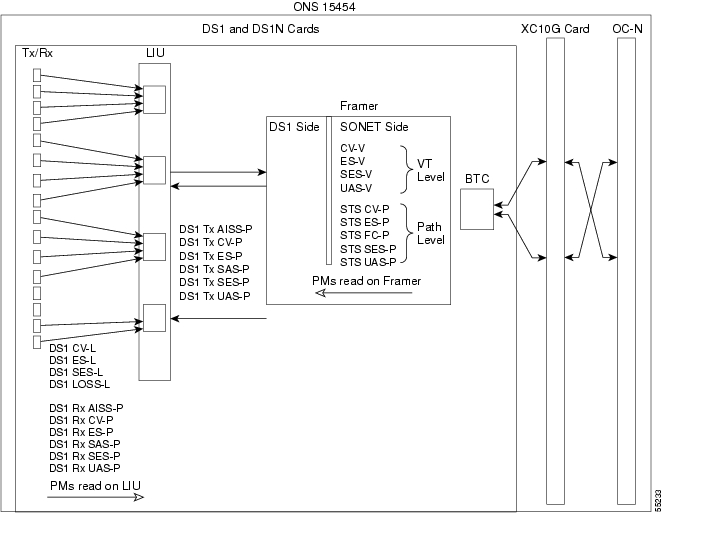
Figure 8-13 shows the signal types that support far-end PMs. Far-end VT and STS path performance monitoring is supported for the DS1 card. Far-end DS1 path performance monitoring is not supported for the DS1 card. Figure 8-14 shows where overhead bytes detected on the ASICs produce performance monitoring parameters for the DS1 and DS1N cards.
Figure 8-13 Monitored signal types for the DS1 and DS1N cards
Note The XX in the illustration above represents all PMs listed below with the given prefix and/or suffix.
Figure 8-14 PM read points on the DS1 and DS1N cards
Table 8-7 DS1 Line PMs for the DS1 and DS1N Cards
Parameter
|
Definition
|
DS1 CV-L
|
Code Violation Line (CV-L) indicates the number of coding violations occurring on the line. This parameter is a count of bipolar violations (BPVs) and excessive zeros (EXZs) occurring over the accumulation period.
|
DS1 ES-L
|
Errored Seconds Line (ES-L) is a count of the seconds containing one or more anomalies (BPV + EXZ) and/or defects (loss of signal) on the line.
|
DS1 SES-L
|
Severely Errored Seconds Line (SES-L) is a count of the seconds containing more than a particular quantity of anomalies (BPV + EXZ > 1544) and/or defects on the line.
|
DS1 LOSS-L
|
Loss of Signal Seconds Line (LOSS-L) is a count of one-second intervals containing one or more LOS defects.
|
Table 8-8 DS1 Receive Path PMs for the DS1 and DS1N Cards
Parameter
|
Definition
|
DS1 Rx AISS-P
|
Receive Path Alarm Indication Signal (Rx AIS-P) means an alarm indication signal occurred on the receive end of the path. This parameter is a count of seconds containing one or more AIS defects.
|
DS1 Rx CV-P
|
Receive Path Code Violation (Rx CV-P) means a coding violation occurred on the receive end of the path. For DS1-ESF paths, this parameter is a count of detected CRC-6 errors. For the DS1-SF paths, the Rx CV-P parameter is a count of detected frame bit errors (FE).
|
DS1 Rx ES-P
|
Receive Path Errored Seconds (Rx ES-P) is a count of the seconds containing one or more anomalies and/or defects for paths on the receive end of the signal. For DS1-ESF paths, this parameter is a count of one-second intervals containing one or more CRC-6 errors, or one or more CS events, or one or more SEF or AIS defects. For DS1-SF paths, the Rx ES-P parameter is a count of one-second intervals containing one or more FE events, or one or more CS events, or one or more SEF or AIS defects.
|
DS1 Rx SAS-P
|
Receive Path Severely Errored Seconds Frame/Alarm Indication Signal (Rx SAS-P) is a count of one-second intervals containing one or more SEFs or one or more AIS defects on the receive end of the signal.
|
DS1 Rx SES-P
|
Receive Path Severely Errored Seconds (Rx SES-P) is a count of the seconds containing more than a particular quantity of anomalies and/or defects for paths on the receive end of the signal. For the DS1-ESF paths, this parameter is a count of seconds when 320 or more CRC-6 errors or one or more SEF or AIS defects occurred. For DS1-SF paths, an SES is a second containing either the occurrence of four FEs or one or more SEF or AIS defects.
|
DS1 Rx UAS-P
|
Receive Path Unavailable Seconds (Rx UAS-P) is a count of one-second intervals when the DS1 path is unavailable on the receive end of the signal. The DS1 path is unavailable when ten consecutive SESs occur. The ten SESs are included in unavailable time. Once unavailable, the DS1 path becomes available when ten consecutive seconds occur with no SESs. The ten seconds with no SESs are excluded from unavailable time.
|
Table 8-9 DS1 Transmit Path PMs for the DS1 and DS1N Cards
Parameter
|
Definition
|
DS1 Tx AISS-P
|
Transmit Path Alarm Indication Signal (Tx AIS-P) means an alarm indication signal occurred on the transmit end of the path. This parameter is a count of seconds containing one or more AIS defects.
|
DS1 Tx CV-P
|
Transmit Path Code Violation (Tx CV-P) means a coding violation occurred on the transmit end of the path. For DS1-ESF paths, this parameter is a count of detected CRC-6 errors. For the DS1-SF paths, the Tx CV-P parameter is a count of detected FEs.
|
DS1 Tx ES-P
|
Transmit Path Errored Seconds (Tx ES-P) is a count of the seconds containing one or more anomalies and/or defects for paths on the transmit end of the signal. For DS1-ESF paths, this parameter is a count of one-second intervals containing one or more CRC-6 errors, or one or more CS events, or one or more SEF or AIS defects. For DS1-SF paths, the Tx ES-P parameter is a count of one-second intervals containing one or more FE events, or one or more CS events, or one or more SEF or AIS defects.
|
DS1 Tx SAS-P
|
Transmit Path Severely Errored Seconds Frame/Alarm Indication Signal (Tx SAS-P) is a count of one-second intervals containing one or more SEFs or one or more AIS defects on the receive end of the signal.
|
DS1 Tx SES-P
|
Transmit Path Severely Errored Seconds (Tx SES-P) is a count of the seconds containing more than a particular quantity of anomalies and/or defects for paths on the transmit end of the signal. For the DS1-ESF paths, this parameter is a count of seconds when 320 or more CRC-6 errors or one or more SEF or AIS defects occurred. For DS1-SF paths, an SES is a second containing either the occurrence of four FEs or one or more SEF or AIS defects.
|
DS1 Tx UAS-P
|
Transmit Path Unavailable Seconds (Tx UAS-P) is a count of one-second intervals when the DS1 path is unavailable on the transmit end of the signal. The DS1 path is unavailable when ten consecutive SESs occur. The ten SESs are included in unavailable time. Once unavailable, the DS1 path becomes available when ten consecutive seconds occur with no SESs. The ten seconds with no SESs are excluded from unavailable time.
|
Table 8-10 VT Path PMs for the DS1 and DS1N Cards
Parameter
|
Definition
|
CV-V
|
Code Violation VT Layer (CV-V) is a count of the BIP errors detected at the VT path layer. Up to two BIP errors can be detected per VT superframe, with each error incrementing the current CV-V second register.
|
ES-V
|
Errored Seconds VT Layer (ES-V) is a count of the seconds when at least one VT Path BIP error was detected. An AIS-V defect (or a lower-layer, traffic-related, near-end defect) or an LOP-V defect can also cause an ES-V.
|
SES-V
|
Severely Errored Seconds VT Layer (SES-V) is a count of seconds when K (600) or more VT Path BIP errors were detected. SES-V can also be caused by an AIS-V defect (or a lower-layer, traffic-related, near-end defect) or an LOP-V defect.
|
UAS-V
|
Unavailable Second VT Layer (UAS-V) is a count of the seconds when the VT path was unavailable. A VT path becomes unavailable when ten consecutive seconds occur that qualify as SES-Vs, and it continues to be unavailable until ten consecutive seconds occur that do not qualify as SES-Vs.
|
Table 8-11 SONET Path PMs for the DS1 and DS1N Cards
Parameter
|
Definition
|
STS CV-P
|
Near-End STS Path Coding Violations (CV-P) is a count of BIP errors detected at the STS path layer (i.e., using the B3 byte). Up to eight BIP errors can be detected per frame, with each error incrementing the current CV-P second register.
|
STS ES-P
|
Near-End STS Path Errored Seconds (ES-P) is a count of the seconds when at least one STS path BIP error was detected. An AIS-P defect (or a lower-layer, traffic-related, near-end defect) or an LOP-P defect can also cause an STS ES-P.
|
STS FC-P
|
Near-End STS Path Failure Counts (FC-P) is a count of the number of near-end STS path failure events. A failure event begins when an AIS-P failure, an LOP-P failure, a UNEQ-P, or a TIM-P failure is declared. A failure event also begins if the STS PTE that is monitoring the path supports ERDI-P for that path. The failure event ends when these failures are cleared.
|
STS SES-P
|
Near-End STS Path Severely Errored Seconds (SES-P) is a count of the seconds when K (2400) or more STS path BIP errors were detected. An AIS-P defect (or a lower-layer, traffic-related, near-end defect) or an LOP-P defect can also cause an STS SES-P.
|
STS UAS-P
|
Near-End STS Path Unavailable Seconds (UAS-P) is a count of the seconds when the STS path was unavailable. An STS path becomes unavailable when ten consecutive seconds occur that qualify as SES-Ps, and it continues to be unavailable until ten consecutive seconds occur that do not qualify as SES-Ps.
|
Table 8-12 Far-End VT Path PMs for the DS1 Card
Parameter
|
Definition
|
CV-V
|
Far-End VT Path Coding Violations (CV-VFE) is a count of the number of BIP errors detected by the far-end VT path terminating equipment (PTE) and reported back to the near-end VT PTE using the REI-V indication in the VT path overhead. Only one BIP error can be indicated per VT superframe using the REI-V bit. The current CV-VFE second register is incremented for each BIP error indicated by the incoming REI-V.
|
ES-V
|
Far-End VT Path Errored Seconds (ES-VFE) is a count of the seconds when at least one VT path BIP error was reported by the far-end VT PTE, or a one-bit RDI-V defect was present.
|
SES-V
|
Far-End VT Path Severely Errored Seconds (SES-VFE) is a count of the seconds when K (600) or more VT path BIP errors were reported by the far-end VT PTE or a one-bit RDI-V defect was present.
|
UAS-V
|
Far-End VT Path Unavailable Seconds (UAS-VFE) is a count of the seconds when the VT path is unavailable at the far-end. A VT path is unavailable at the far-end when ten consecutive seconds occur that qualify as SES-VFEs.
|
8.5.3 DS3 and DS3N Card Performance Monitoring Parameters
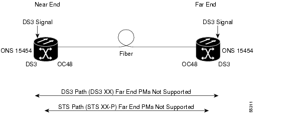
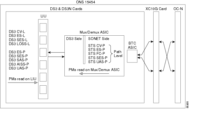
Figure 8-15 shows the signal types that support far-end PMs. Figure 8-16 shows where overhead bytes detected on the ASICs produce performance monitoring parameters for the DS3 and DS3N cards.
Figure 8-15 Monitored signal types for the DS3 and DS3N cards
Note The XX in the illustration above represents all PMs listed below with the given prefix and/or suffix.
Figure 8-16 PM read points on the DS3 and DS3N cards
Table 8-13 Near-End DS3 Line PMs for the DS3 and DS3N Cards
Parameter
|
Definition
|
DS3 CV-L
|
Code Violation Line (CV-L) indicates the number of coding violations occurring on the line. This parameter is a count of bipolar violations (BPVs) and excessive zeros (EXZs) occurring over the accumulation period.
|
DS3 ES-L
|
Errored Seconds Line (ES-L) is a count of the seconds containing one or more anomalies (BPV + EXZ) and/or defects (loss of signal) on the line.
|
DS3 SES-L
|
Severely Errored Seconds Line (SES-L) is a count of the seconds containing more than a particular quantity of anomalies (BPV + EXZ > 44) and/or defects on the line.
|
DS3 LOSS-L
|
Line Loss of Signal (LOSS-L) is a count of one-second intervals containing one or more LOS defects.
|
Table 8-14 Near-End DS3 Path PMs for the DS3 and DS3N Cards
Parameter
|
Definition
|
DS3 ES-P
|
Errored Seconds-Path (ES-P) is a count of one-second intervals containing one or more CRC-6 errors, or one or more CS events, or one or more SEF or AIS defects.
|
DS3 SES-P
|
Severely Errored Seconds-Path (SES-P) is a count of seconds where 320 or more CRC-6 errors occur or one or more SEF or AIS defects occur.
|
DS3 SAS-P
|
Severely Errored Frame/Alarm Indication Signal-Path (SAS-P) is a count of seconds containing one or more SEFs or one or more AIS defects.
|
DS3 AISS-P
|
Alarm Indication Signal Seconds-Path (AISS-P) is a count of seconds containing one or more AIS defects.
|
DS3 UAS-P
|
Unavailable Seconds-Path (UAS-P) is a count of one-second intervals during which the DS3 path is unavailable.
|
Table 8-15 Near-End SONET Path PMs for the DS3 and DS3N Cards
Parameter
|
Definition
|
STS CV-P
|
Near-End STS Path Coding Violations (CV-P) is a count of BIP errors detected at the STS path layer (i.e., using the B3 byte). Up to eight BIP errors can be detected per frame; each error increments the current CV-P second register.
|
STS ES-P
|
Near-End STS Path Errored Seconds (ES-P) is a count of the seconds when at least one STS path BIP error was detected. An AIS-P defect (or a lower-layer, traffic-related, near-end defect) or an LOP-P defect can also cause an STS ES-P.
|
STS FC-P
|
Near-End STS Path Failure Counts (FC-P) is a count of the number of near-end STS path failure events. A failure event begins when an AIS-P failure, an LOP-P failure, a UNEQ-P, or a TIM-P failure is declared. A failure event also begins if the STS PTE that is monitoring the path supports ERDI-P for that path. The failure event ends when these failures are cleared.
|
STS SES-P
|
Near-End STS Path Severely Errored Seconds (SES-P) is a count of the seconds when K (2400) or more STS path BIP errors were detected. An AIS-P defect (or a lower-layer, traffic-related, near-end defect) or an LOP-P defect can also cause an STS SES-P.
|
STS UAS-P
|
Near-End STS Path Unavailable Seconds (UAS-P) is a count of the seconds when the STS path was unavailable. An STS path becomes unavailable when ten consecutive seconds occur that qualify as SES-Ps, and it continues to be unavailable until ten consecutive seconds occur that do not qualify as SES-Ps.
|
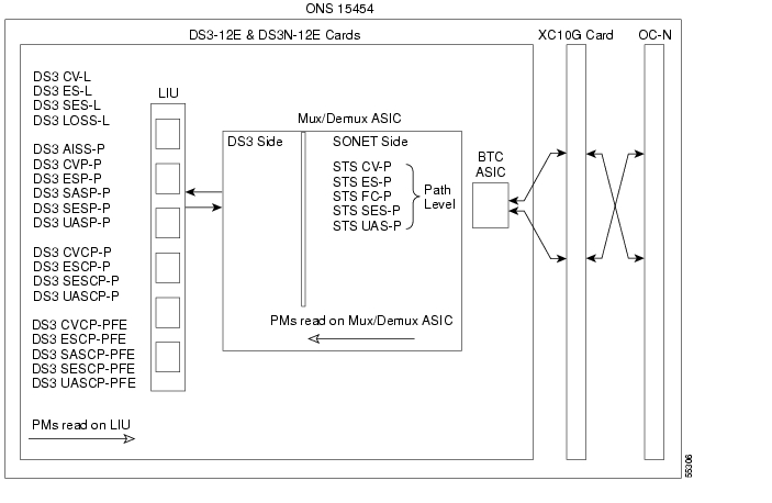
8.5.4 DS3-12E and DS3N-12E Card Performance Monitoring Parameters
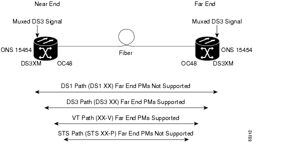
Figure 8-17 shows the signal types that support far-end PMs. Figure 8-18 shows where overhead bytes detected on the ASICs produce performance monitoring parameters for the DS3-12E and DS3N-12E cards.
Figure 8-17 Monitored signal types for the DS3-12E and DS3N-12E cards
Note The XX in the illustration above represents all PMs listed below with the given prefix and/or suffix.
Figure 8-18 PM read points on the DS3-12E and DS3N-12E cards
Table 8-16 Near-End DS3 Line PMs for the DS3-12E and DS3N-12E Cards
Parameter
|
Definition
|
DS3 CV-L
|
Code Violation Line (CV-L) indicates the number of coding violations occurring on the line. This parameter is a count of bipolar violations (BPVs) and excessive zeros (EXZs) occurring over the accumulation period.
|
DS3 ES-L
|
Errored Seconds Line (ES-L) is a count of the seconds containing one or more anomalies (BPV + EXZ) and/or defects (i.e. loss of signal) on the line.
|
DS3 SES-L
|
Severely Errored Seconds Line (SES-L) is a count of the seconds containing more than a particular quantity of anomalies (BPV + EXZ > 44) and/or defects on the line.
|
DS3 LOSS-L
|
Line Loss of Signal (LOSS-L) is a count of one-second intervals containing one or more LOS defects.
|
Table 8-17 Near-End DS3 Path PMs for the DS3-12E and DS3N-12E Cards
Parameter
|
Definition
|
DS3 AISS-P
|
AIS Seconds Path (AISS-P) is a count of one-second intervals containing one or more AIS defects.
|
DS3 CVP-P
|
Code Violation Path (CVP-P) is a code violation parameter for M23 applications. CVP-P is a count of P-bit parity errors occurring in the accumulation period.
|
DS3 ESP-P
|
Errored Second Path (ESP-P) is a count of seconds containing one or more P-bit parity errors, one or more SEF defects, or one or more AIS defects.
|
DS3 SASP-P
|
SEF/AIS Seconds Path (SASP-P) is a count of one-second intervals containing one or more SEFs or one or more AIS defects on the path.
|
DS3 SESP-P
|
Severely Errored Seconds Path (DS3 SESP-P) is a count of seconds containing more than 44 P-bit parity violations, one or more SEF defects, or one or more AIS defects.
|
DS3 UASP-P
|
Unavailable Second Path (DS3 UASP-P) is a count of one-second intervals when the DS3 path is unavailable. A DS3 path becomes unavailable when ten consecutive SESP-Ps occur. The ten SESP-Ps are included in unavailable time. Once unavailable, the DS3 path becomes available when ten consecutive seconds with no SESP-Ps occur. The ten seconds with no SESP-Ps are excluded from unavailable time.
|
Table 8-18 Near-End CP-bit Path PMs for the DS3-12E and DS3N-12E Cards
Parameter
|
Definition
|
DS3 CVCP-P
|
Code Violation Path (CVCP-P) is a count of CP-bit parity errors occurring in the accumulation period.
|
DS3 ESCP-P
|
Errored Second Path (ESCP-P) is a count of seconds containing one or more CP-bit parity errors, one or more SEF defects, or one or more AIS defects. ESCP-P is defined for the C-bit parity application.
|
DS3 SESCP-P
|
Severely Errored Seconds Path (SESCP-P) is a count of seconds containing more than 44 CP-bit parity errors, one or more SEF defects, or one or more AIS defects.
|
DS3 UASCP-P
|
Unavailable Second Path (UASCP-P) is a count of one-second intervals when the DS3 path is unavailable. A DS3 path becomes unavailable when ten consecutive SESCP-Ps occur. The ten SESCP-Ps are included in unavailable time. Once unavailable, the DS3 path becomes available when ten consecutive seconds with no SESCP-Ps occur. The ten seconds with no SESCP-Ps are excluded from unavailable time.
|
Table 8-19 Near-End SONET Path PMs for the DS3-12E and DS3N-12E Cards
Parameter
|
Definition
|
STS CV-P
|
Near-End STS Path Coding Violations (CV-P) is a count of BIP errors detected at the STS path layer (i.e., using the B3 byte). Up to eight BIP errors can be detected per frame; each error increments the current CV-P second register.
|
STS ES-P
|
Near-End STS Path Errored Seconds (ES-P) is a count of the seconds when at least one STS path BIP error was detected. An AIS-P defect (or a lower-layer, traffic-related, near-end defect) or an LOP-P defect can also cause an STS ES-P.
|
STS FC-P
|
Near-End STS Path Failure Counts (FC-P) is a count of the number of near-end STS path failure events. A failure event begins when an AIS-P failure, an LOP-P failure, a UNEQ-P, or a TIM-P failure is declared. A failure event also begins if the STS PTE that is monitoring the path supports ERDI-P for that path. The failure event ends when these failures are cleared.
|
STS SES-P
|
Near-End STS Path Severely Errored Seconds (SES-P) is a count of the seconds when K (2400) or more STS path BIP errors were detected. An AIS-P defect (or a lower-layer, traffic-related, near-end defect) or an LOP-P defect can also cause an STS SES-P.
|
STS UAS-P
|
Near-End STS Path Unavailable Seconds (UAS-P) is a count of the seconds when the STS path was unavailable. An STS path becomes unavailable when ten consecutive seconds occur that qualify as SES-Ps, and continues to be unavailable until ten consecutive seconds occur that do not qualify as SES-Ps.
|
Table 8-20 Far-End CP-bit Path PMs for the DS3-12E and DS3N-12E Cards
Parameter
|
Definition
|
DS3 CVCP-P
|
Code Violation (CVCP-PFE) is a parameter that is counted when the three far-end block error (FEBE) bits in a M-frame are not all collectively set to 1.
|
DS3 ESCP-P
|
Errored Second (ESCP-PFE) is a count of one-second intervals containing one or more M-frames with the three FEBE bits not all collectively set to 1 or one or more far-end SEF/AIS defects.
|
DS3 SASCP-P
|
SEF/AIS Second (SASCP-PFE) is a count of one-second intervals containing one or more far-end SEF/AIS defects.
|
DS3 SESCP-P
|
Severely Errored Second (SESCP-PFE) is a count of one-second intervals containing one or more 44 M-frames with the three FEBE bits not all collectively set to 1 or one or more far-end SEF/AIS defects.
|
DS3 UASCP-P
|
Unavailable Second (UASCP-PFE) is a count of one-second intervals when the DS3 path becomes unavailable. A DS3 path becomes unavailable when ten consecutive far-end CP-bit SESs occur. The ten CP-bit SESs are included in unavailable time. Once unavailable, the DS3 path becomes available when ten consecutive seconds occur with no CP-bit SESs. The ten seconds with no CP-bit SESs are excluded from unavailable time.
|
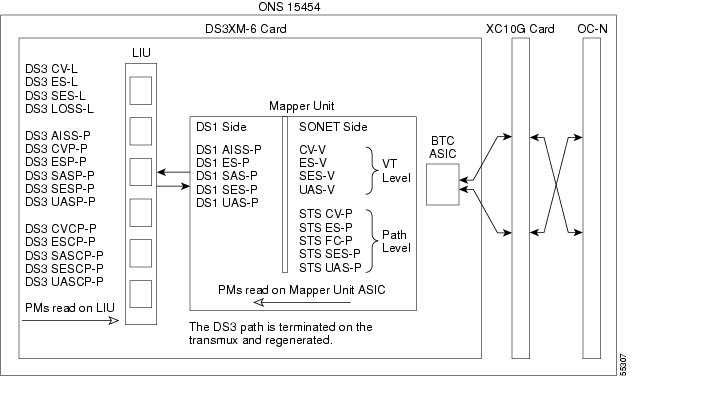
8.5.5 DS3XM-6 Card Performance Monitoring Parameters
Figure 8-19 shows the signal types that support far-end PMs. Figure 8-20 shows where overhead bytes detected on the ASICs produce performance monitoring parameters for the DS3XM-6 card.
Figure 8-19 Monitored signal types for the DS3XM-6 card
Note The XX in the illustration above represents all PMs listed below with the given prefix and/or suffix.
Figure 8-20 PM read points on the DS3XM-6 card
Table 8-21 Near-End DS3 Line PMs for the DS3XM-6 Card
Parameter
|
Definition
|
DS3 CV-L
|
Code Violation Line (CV-L) indicates the number of coding violations occurring on the line. This parameter is a count of bipolar violations (BPVs) and excessive zeros (EXZs) occurring over the accumulation period.
|
DS3 ES-L
|
Errored Seconds Line (ES-L) is a count of the seconds containing one or more anomalies (BPV + EXZ) and/or defects (i.e. LOS) on the line.
|
DS3 SES-L
|
Severely Errored Seconds Line (SES-L) is a count of the seconds containing more than a particular quantity of anomalies (BPV + EXZ > 44) and/or defects on the line.
|
DS3 LOSS-L
|
Line Loss of Signal (LOSS-L) is a count of one-second intervals containing one or more LOS defects.
|
Table 8-22 Near-End DS3 Path PMs for the DS3XM-6 Card
Parameter
|
Definition
|
DS3 AISS-P
|
AIS Seconds Path (AISS-P) is a count of one-second intervals containing one or more AIS defects.
|
DS3 CVP-P
|
Code Violation Path (CVP-P) is a code violation parameter for M23 applications. CVP-P is a count of P-bit parity errors occurring in the accumulation period.
|
DS3 ESP-P
|
Errored Second Path (ESP-P) is a count of seconds containing one or more P-bit parity errors, one or more SEF defects, or one or more AIS defects.
|
DS3 SASP-P
|
SEF/AIS Seconds Path (SASP-P) is a count of one-second intervals containing one or more SEFs or one or more AIS defects on the path.
|
DS3 SESP-P
|
Severely Errored Seconds Path (SESP-P) is a count of seconds containing more than 44 P-bit parity violations, one or more SEF defects, or one or more AIS defects.
|
DS3 UASP-P
|
Unavailable Second Path (UASP-P) is a count of one-second intervals when the DS3 path is unavailable. A DS3 path becomes unavailable when ten consecutive SESP-Ps occur. The ten SESP-Ps are included in unavailable time. Once unavailable, the DS3 path becomes available when ten consecutive seconds with no SESP-Ps occur. The ten seconds with no SESP-Ps are excluded from unavailable time.
|
Table 8-23 Near-End CP-bit Path PMs for the DS3XM-6 Card
Parameter
|
Definition
|
DS3 CVCP-P
|
Code Violation Path (CVCP-P) is a count of CP-bit parity errors occurring in the accumulation period.
|
DS3 ESCP-P
|
Errored Second Path (ESCP-P) is a count of seconds containing one or more CP-bit parity errors, one or more SEF defects, or one or more AIS defects.
|
DS3 SESCP-P
|
Severely Errored Seconds Path (SESCP-P) is a count of seconds containing more than 44 CP-bit parity errors, one or more SEF defects, or one or more AIS defects.
|
DS3 UASCP-P
|
Unavailable Seconds Path (DS3 UASCP-P) is a count of one-second intervals when the DS3 path is unavailable. A DS3 path becomes unavailable when ten consecutive SESCP-Ps occur. The ten SESCP-Ps are included in unavailable time. Once unavailable, the DS3 path becomes available when ten consecutive seconds with no SESCP-Ps occur. The ten seconds with no SESCP-Ps are excluded from unavailable time.
|
Table 8-24 Near-End DS1 Path PMs for the DS3XM-6 Card
Parameter
|
Definition
|
DS1 AISS-P
|
Alarm Indication Signal Path (AIS-P) means an AIS occurred on the path. This parameter is a count of seconds containing one or more AIS defects.
|
DS1 ES-P
|
Errored Seconds Path (ES-P) is a count of the seconds containing one or more anomalies and/or defects for paths. For DS1-ESF paths, this parameter is a count of one-second intervals containing one or more CRC-6 errors, or one or more CS events, or one or more SEF or AIS defects. For DS1-SF paths, the ES-P parameter is a count of one-second intervals containing one or more FE events, or one or more CS events, or one or more SEF or AIS defects.
|
DS1 SAS-P
|
Severely Errored Seconds Path Frame/Alarm Indication Signal (SAS-P) is a count of one-second intervals containing one or more SEFs or one or more AIS defects.
|
DS1 SES-P
|
Severely Errored Seconds Path (SES-P) is a count of the seconds containing more than a particular quantity of anomalies and/or defects for paths. For the DS1-ESF paths, this parameter is a count of seconds when 320 or more CRC-6 errors or one or more SEF or AIS defects occurs. For DS1-SF paths, an SES is a second containing either the occurrence of eight FEs, four FEs, or one or more SEF or AIS defects.
|
DS1 UAS-P
|
Unavailable Seconds Path (UAS-P) is a count of one-second intervals when the DS1 path is unavailable. The DS1 path is unavailable when ten consecutive SESs occur. The ten SESs are included in unavailable time. Once unavailable, the DS1 path becomes available when ten consecutive seconds occur with no SESs. The ten seconds with no SESs are excluded from unavailable time.
|
Table 8-25 Near-End VT PMs for the DS3XM-6 Card
Parameter
|
Definition
|
CV-V
|
Code Violation VT Layer (CV-V) is a count of the BIP errors detected at the VT path layer. Up to two BIP errors can be detected per VT superframe; each error increments the current CV-V second register.
|
ES-V
|
Errored Seconds VT Layer (ES-V) is a count of the seconds when at least one VT Path BIP error was detected. An AIS-V defect (or a lower-layer, traffic-related, near-end defect) or an LOP-V defect can also cause ES-V.
|
SES-V
|
Severely Errored Seconds VT Layer (SES-V) is a count of seconds when K (600) or more VT Path BIP errors were detected. An AIS-V defect (or a lower-layer, traffic-related, near-end defect) or an LOP-V defect can also cause SES-V.
|
UAS-V
|
Unavailable Seconds VT Layer (UAS-V) is a count of the seconds when the VT path was unavailable. A VT path becomes unavailable when ten consecutive seconds occur that qualify as SES-Vs and continues to be unavailable until ten consecutive seconds occur that do not qualify as SES-Vs.
|
Table 8-26 Near-End SONET Path PMs for the DS3XM-6 Card
Parameter
|
Definition
|
STS CV-P
|
Near-End STS Path Coding Violations (CV-P) is a count of BIP errors detected at the STS path layer (i.e., using the B3 byte). Up to eight BIP errors can be detected per frame; each error increments the current CV-P second register.
|
STS ES-P
|
Near-End STS Path Errored Seconds (ES-P) is a count of the seconds when at least one STS path BIP error was detected. An AIS-P defect (or a lower-layer, traffic-related, near-end defect) or an LOP-P defect can also cause an STS ES-P.
|
STS FC-P
|
Near-End STS Path Failure Counts (FC-P) is a count of the number of near-end STS path failure events. A failure event begins when an AIS-P failure, an LOP-P failure, a UNEQ-P, or a TIM-P failure is declared. A failure event also begins if the STS PTE that is monitoring the path supports ERDI-P for that path. The failure event ends when these failures are cleared.
|
STS SES-P
|
Near-End STS Path Severely Errored Seconds (SES-P) is a count of the seconds when K (2400) or more STS path BIP errors were detected. An AIS-P defect (or a lower-layer, traffic-related, near-end defect) or an LOP-P defect can also cause an STS SES-P.
|
STS UAS-P
|
Near-End STS Path Unavailable Seconds (UAS-P) is a count of the seconds when the STS path was unavailable. An STS path becomes unavailable when ten consecutive seconds occur that qualify as SES-Ps, and it continues to be unavailable until ten consecutive seconds occur that do not qualify as SES-Ps.
|
Table 8-27 Far-End CP-bit Path PMs for the DS3XM-6 Card
Parameter
|
Definition
|
DS3 CVCP-P
|
Code Violation (CVCP-PFE) is a parameter that is counted when the three FEBE bits in a M-frame are not all collectively set to 1.
|
DS3 ESCP-P
|
Errored Second (ESCP-PFE) is a count of one-second intervals containing one or more M-frames with the three FEBE bits not all collectively set to 1 or one or more far-end SEF/AIS defects.
|
DS3 SASCP-P
|
SEF/AIS Second (SASCP-PFE) is a count of one-second intervals containing one or more far-end SEF/AIS defects.
|
DS3 SESCP-P
|
Severely Errored Second (SESCP-PFE) is a count of one-second intervals containing one or more 44 M-frames with the three FEBE bits not all collectively set to 1 or one or more far-end SEF/AIS defects.
|
DS3 UASCP-P
|
Unavailable Second (UASCP-PFE) is a count of one-second intervals when the DS3 path becomes unavailable. A DS3 path becomes unavailable when ten consecutive far-end CP-bit SESs occur. The ten CP-bit SESs are included in unavailable time. Once unavailable, the DS3 path becomes available when ten consecutive seconds with no CP-bit SESs occur. The ten seconds with no CP-bit SESs are excluded from unavailable time.
|
Table 8-28 Far-End VT PMs for the DS3XM-6 Card
Parameter
|
Definition
|
CV-V
|
Code Violation VT Layer (CV-V) is a count of the BIP errors detected at the VT path layer. Up to two BIP errors can be detected per VT superframe; each error increments the current CV-V second register.
|
ES-V
|
Errored Seconds VT Layer (ES-V) is a count of the seconds when at least one VT Path BIP error was detected. An AIS-V defect (or a lower-layer, traffic-related, near-end defect) or an LOP-V defect can also cause an ES-V.
|
SES-V
|
Severely Errored Seconds VT Layer (SES-V) is a count of seconds when K (600) or more VT Path BIP errors were detected. An AIS-V defect (or a lower-layer, traffic-related, near-end defect) or an LOP-V defect can also cause an SES-V.
|
UAS-V
|
Unavailable Second VT Layer (UAS-V) is a count of the seconds when the VT path was unavailable. A VT path becomes unavailable when ten consecutive seconds occur that qualify as SES-Vs and continues to be unavailable until ten consecutive seconds occur that do not qualify as SES-Vs.
|
8.6 Performance Monitoring for Optical Cards
The following sections define performance monitoring parameters and definitions for the OC-3, OC-12, OC-48, and OC-192.
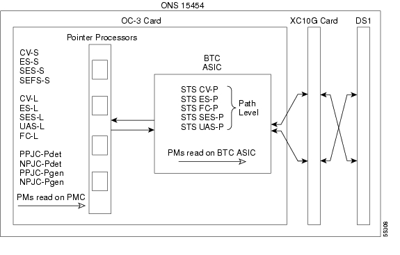
8.6.1 OC-3 Card Performance Monitoring Parameters
Figure 8-21 shows where overhead bytes detected on the ASICs produce performance monitoring parameters for the OC-3 card.
Figure 8-21 PM read points on the OC-3 card
Note For PM locations relating to protection switch counts, see the GR-253-CORE document.
Table 8-29 Near-End Section PMs for the OC-3 Card
Parameter
|
Definition
|
CV-S
|
Section Coding Violation (CV-S) is a count of BIP errors detected at the section-layer (i.e. using the B1 byte in the incoming SONET signal). Up to eight section BIP errors can be detected per STS-N frame, with each error incrementing the current CV-S second register.
|
ES-S
|
Section Errored Seconds (ES-S) is a count of the number of seconds when at least one section-layer BIP error was detected or an SEF or LOS defect was present.
|
SES-S
|
Section Severely Errored Seconds (SES-S) is a count of the seconds when K (see GR-253 for value) or more section-layer BIP errors were detected or an SEF or LOS defect was present.
|
SEFS-S
|
Section Severely Errored Framing Seconds (SEFS-S) is a count of the seconds when an SEF defect was present. An SEF defect is expected to be present during most seconds when an LOS or LOF defect is present. However, there can be situations when the SEFS-S parameter is only incremented based on the presence of the SEF defect.
|
Table 8-30 Near-End Line Layer PMs for the OC-3 Card
Parameter
|
Definition
|
CV-L
|
Near-End Line Code Violation (CV-L) is a count of BIP errors detected at the line-layer (i.e. using the B2 bytes in the incoming SONET signal). Up to 8 x N BIP errors can be detected per STS-N frame; each error increments the current CV-L second register.
|
ES-L
|
Near-End Line Errored Seconds (ES-L) is a count of the seconds when at least one line-layer BIP error was detected or an AIS-L defect was present.
|
SES-L
|
Near-End Line Severely Errored Seconds (SES-L) is a count of the seconds when K (see GR-253-CORE for values) or more line-layer BIP errors were detected or an AIS-L defect was present.
|
UAS-L
|
Near-End Line Unavailable Seconds (UAS-L) is a count of the seconds when the line is unavailable. A line becomes unavailable when ten consecutive seconds occur that qualify as SES-Ls, and it continues to be unavailable until ten consecutive seconds occur that do not qualify as SES-Ls.
|
FC-L
|
Near-End Line Failure Count (FC-L) is a count of the number of near-end line failure events. A failure event begins when an AIS-L failure is declared or when a lower-layer traffic-related, near-end failure is declared. This failure event ends when the failure is cleared. A failure event that begins in one period and ends in another period is counted only in the period where it begins.
|
Table 8-31 Near-End Line Layer PMs for the OC-3 Cards
Parameter
|
Definition
|
PSC (1+1 protection)
|
In a 1 + 1 protection scheme for a working card, Protection Switching Count (PSC) is a count of the number of times service switches from a working card to a protection card plus the number of times service switches back to the working card.
For a protection card, PSC is a count of the number of times service switches to a working card from a protection card plus the number of times service switches back to the protection card. The PSC PM is only applicable if revertive line-level protection switching is used.
Note BLSR is not supported on the OC-3 card; therefore, the PSC-W, PSC-S, and PSC-R PMs do not increment.
|
PSD
|
Protection Switching Duration (PSD) applies to the length of time, in seconds, that service is carried on another line. For a working line, PSD is a count of the number of seconds that service was carried on the protection line.
For the protection line, PSD is a count of the seconds that the line was used to carry service. The PSD PM is only applicable if revertive line-level protection switching is used.
Note BLSR is not supported on the OC-3 card; therefore, the PSD-W, PSD-S, and PSD-R PMs do not increment.
|
Table 8-32 Near-End SONET Path H-byte PMs for the OC-3 Card
Parameter
|
Definition
|
PPJC-Pdet
|
Positive Pointer Justification Count, STS Path Detected (PPJC-Pdet) is a count of the positive pointer justifications detected on a particular path on an incoming SONET signal.
|
NPJC-Pdet
|
Negative Pointer Justification Count, STS Path Detected (NPJC-Pdet) is a count of the negative pointer justifications detected on a particular path on an incoming SONET signal.
|
PPJC-Pgen
|
Positive Pointer Justification Count, STS Path Generated (PPJC-Pgen) is a count of the positive pointer justifications generated for a particular path to reconcile the frequency of the SPE with the local clock.
|
NPJC-Pgen
|
Negative Pointer Justification Count, STS Path Generated (NPJC-Pgen) is a count of the negative pointer justifications generated for a particular path to reconcile the frequency of the synchronous payload envelope (SPE) with the local clock.
|
Table 8-33 Near-End SONET Path PMs for the OC-3 Card
Parameter
|
Definition
|
Note SONET path PMs will not count unless IPPM is enabled. For additional information, see the "Enable Intermediate-Path Performance Monitoring" procedure on page 7-25. The far-end IPPM feature is not supported in Software R3.1. However, SONET path PMs can be monitored by logging into the far-end node directly.
|
STS CV-P
|
Near-End STS Path Coding Violations (CV-P) is a count of BIP errors detected at the STS path layer (i.e., using the B3 byte). Up to eight BIP errors can be detected per frame; each error increments the current CV-P second register.
|
STS ES-P
|
Near-End STS Path Errored Seconds (ES-P) is a count of the seconds when one or more STS path BIP errors were detected. An AIS-P defect (or a lower-layer, traffic-related, near-end defect) or an LOP-P defect can also cause an STS ES-P.
|
STS FC-P
|
Near-End STS Path Failure Counts (FC-P) is a count of the number of near-end STS path failure events. A failure event begins with an AIS-P failure, an LOP-P failure, a UNEQ-P failure, or a TIM-P failure is declared, or if the STS PTE that is monitoring the path supports ERDI-P for that path. The failure event ends when these failures are cleared.
|
STS SES-P
|
Near-End STS Path Severely Errored Seconds (SES-P) is a count of the seconds when K (2400) or more STS path BIP errors were detected. An AIS-P defect (or a lower-layer, traffic-related, near-end defect) or an LOP-P defect can also cause an STS SES-P.
|
STS UAS-P
|
Near-End STS Path Unavailable Seconds (UAS-P) is a count of the seconds when the STS path was unavailable. An STS path becomes unavailable when ten consecutive seconds occur that qualify as SES-Ps, and it continues to be unavailable until ten consecutive seconds occur that do not qualify as SES-Ps.
|
Table 8-34 Far-End Line Layer PMs for the OC-3 Card
Parameter
|
Definition
|
CV-L
|
Far-End Line Code Violation (CV-L) is a count of BIP errors detected by the far-end line terminating equipment (LTE) and reported back to the near-end LTE using the REI-L indication in the line overhead. For SONET signals at rates below OC-48, up to 8 x N BIP errors per STS-N frame can be indicated using the REI-L. For OC-48 signals, up to 255 BIP errors per STS-N frame can be indicated. The current CV-L second register is incremented for each BIP error indicated by the incoming REI-L.
|
ES-L
|
Far-End Line Errored Seconds (ES-L) is a count of the seconds when at least one line-layer BIP error was reported by the far-end LTE or an RDI-L defect was present.
|
SES-L
|
Far-End Line Severely Errored Seconds (SES-L) is a count of the seconds when K (see GR-253-CORE for values) or more line-layer BIP errors were reported by the far-end LTE or an RDI-L defect was present.
|
UAS-L
|
Far-End Line Unavailable Seconds (UAS-L) is a count of the seconds when the line is unavailable at the far end. A line becomes unavailable at the far end when ten consecutive seconds occur that qualify as SES-LFEs and it continues to be unavailable until ten consecutive seconds occur that do not qualify as SES-LFEs.
|
FC-L
|
Far-End Line Failure Count (FC-L) is a count of the number of far-end line failure events. A failure event begins when RFI-L failure is declared, and it ends when the RFI-L failure clears. A failure event that begins in one period and ends in another period is counted only in the period where it began.
|
8.6.2 OC-12, OC-48, and OC-192 Card Performance Monitoring Parameters
Figure 8-22 shows the signal types that support far-end PMs. Figure 8-23 shows where overhead bytes detected on the ASICs produce performance monitoring parameters for the OC-12, OC-48, and OC-192 cards.
Figure 8-22 Monitored signal types for the OC-12, OC-48, and OC-192 cards
Note PMs on the protect STS are not supported for BLSR. The XX in the illustration above represents all PMs listed below with the given prefix and/or suffix.
Figure 8-23 PM read points on the OC-12, OC-48, and OC-192 cards
Note For PM locations relating to protection switch counts, see the GR-1230-CORE document.
Table 8-35 Near-End Section PMs for the OC-12, OC-48, and OC-192 Cards
Parameter
|
Definition
|
CV-S
|
Section Coding Violation (CV-S) is a count of BIP errors detected at the section-layer (i.e. using the B1 byte in the incoming SONET signal). Up to eight section BIP errors can be detected per STS-N frame; each error increments the current CV-S second register.
|
ES-S
|
Section Errored Seconds (ES-S) is a count of the number of seconds when at least one section-layer BIP error was detected or an SEF or LOS defect was present.
|
SES-S
|
Section Severely Errored Seconds (SES-S) is a count of the seconds when K (see GR-253 for value) or more section-layer BIP errors were detected or an SEF or LOS defect was present.
|
SEFS-S
|
Section Severely Errored Framing Seconds (SEFS-S) is a count of the seconds when an SEF defect was present. An SEF defect is expected to be present during most seconds when an LOS or LOF defect is present. However, there may be situations when the SEFS-S parameter is only incremented based on the presence of an SEF defect.
|
Table 8-36 Near-End Line Layer PMs for the OC-12, OC-48, and OC-192 Cards
Parameter
|
Definition
|
CV-L
|
Near-End Line Code Violation (CV-L) is a count of BIP errors detected at the line-layer (i.e. using the B2 bytes in the incoming SONET signal). Up to 8 x N BIP errors can be detected per STS-N frame; each error increments the current CV-L second register.
|
ES-L
|
Near-End Line Errored Seconds (ES-L) is a count of the seconds when at least one line-layer BIP error was detected or an AIS-L defect was present.
|
SES-L
|
Near-End Line Severely Errored Seconds (SES-L) is a count of the seconds when K (see GR-253 for values) or more line-layer BIP errors were detected or an AIS-L defect was present.
|
UAS-L
|
Near-End Line Unavailable Seconds (UAS-L) is a count of the seconds when the line is unavailable. A line becomes unavailable when ten consecutive seconds occur that qualify as SES-Ls, and it continues to be unavailable until ten consecutive seconds occur that do not qualify as SES-Ls.
|
FC-L
|
Near-End Line Failure Count (FC-L) is a count of the number of near-end line failure events. A failure event begins when an AIS-L failure or a lower-layer traffic-related, near-end failure is declared. This failure event ends when the failure is cleared. A failure event that begins in one period and ends in another period is counted only in the period where it begins.
|
Table 8-37 Near-End SONET Path H-byte PMs for the OC-12, OC-48, and OC-192 Cards
Parameter
|
Definition
|
PPJC-Pdet
|
Positive Pointer Justification Count, STS Path Detected (PPJC-Pdet) is a count of the positive pointer justifications detected on a particular path on an incoming SONET signal.
|
NPJC-Pdet
|
Negative Pointer Justification Count, STS Path Detected (NPJC-Pdet) is a count of the negative pointer justifications detected on a particular path on an incoming SONET signal.
|
PPJC-Pgen
|
Positive Pointer Justification Count, STS Path Generated (PPJC-Pgen) is a count of the positive pointer justifications generated for a particular path to reconcile the frequency of the SPE with the local clock.
|
NPJC-Pgen
|
Negative Pointer Justification Count, STS Path Generated (PPJC-Pgen) is a count of the negative pointer justifications generated for a particular path to reconcile the frequency of the synchronous payload envelope (SPE) with the local clock.
|
Table 8-38 Near-End Line Layer PMs for the OC-12, OC-48, and OC-192 Cards
Parameter
|
Definition
|
PSC (BLSR)
|
For a protect line in a 2-fiber ring, Protection Switching Count (PSC) refers to the number of times a protection switch has occurred either to a particular span's line protection or away from a particular span's line protection. Therefore, if a protection switch occurs on a 2-fiber BLSR, the PSC of the protection span to which the traffic is switched will increment, and when the switched traffic returns to its original working span from the protect span, the PSC of the protect span will increment again.
|
PSC (1+1 protection)
|
In a 1 + 1 protection scheme for a working card, Protection Switching Count (PSC) is a count of the number of times service switches from a working card to a protection card plus the number of times service switches back to the working card.
For a protection card, PSC is a count of the number of times service switches to a working card from a protection card plus the number of times service switches back to the protection card. The PSC PM is only applicable if revertive line-level protection switching is used.
|
PSD
|
For an active protection line in a 2-fiber BLSR, Protection Switching Duration (PSD) is a count of the number of seconds that the protect line is carrying working traffic following the failure of the working line. PSD increments on the active protect line and PSD-W increments on the failed working line.
|
PSC-W
|
For a working line in a 2-fiber BLSR, Protection Switching Count-Working (PSC-W) is a count of the number of times traffic switches away from the working capacity in the failed line and back to the working capacity after the failure is cleared. PSC-W increments on the failed working line and PSC increments on the active protect line.
For a working line in a 4-fiber BLSR, PSC-W is a count of the number of times service switches from a working line to a protection line plus the number of times it switches back to the working line. PSC-W increments on the failed line and PSC-R or PSC-S increments on the active protect line.
|
PSD-W
|
For a working line in a 2-fiber BLSR, Protection Switching Duration-Working (PSD-W) is a count of the number of seconds that service was carried on the protection line. PSD-W increments on the failed working line and PSD increments on the active protect line.
|
PSC-S
|
In a 4-fiber BLSR, Protection Switching Count-Span (PSC-S) is a count of the number of times service switches from a working line to a protection line plus the number of times it switches back to the working line. A count is only incremented if span switching is used.
|
PSD-S
|
In a 4-fiber BLSR, Protection Switching Duration-Span (PSD-S) is a count of the seconds that the protection line was used to carry service. A count is only incremented if span switching is used.
|
PSC-R
|
In a 4-fiber BLSR, Protection Switching Count-Ring (PSC-R) is a count of the number of times service switches from a working line to a protection line plus the number of times it switches back to a working line. A count is only incremented if ring switching is used.
|
PSD-R
|
In a 4-fiber BLSR, Protection Switching Duration-Ring (PSD-R) is a count of the seconds that the protection line was used to carry service. A count is only incremented if ring switching is used.
|
Table 8-39 Near-End SONET Path PMs for the OC-12, OC-48, and OC-192 Cards
Parameter
|
Definition
|
Note SONET path PMs will not count unless IPPM is enabled. For additional information, see the "Enable Intermediate-Path Performance Monitoring" procedure on page 7-25. The far-end IPPM feature is not supported in Software R3.1. However, SONET path PMs can be monitored by logging into the far-end node directly.
|
STS CV-P
|
Near-End STS Path Coding Violations (CV-P) is a count of BIP errors detected at the STS path layer (i.e., using the B3 byte). Up to eight BIP errors can be detected per frame; each error increments the current CV-P second register.
|
STS ES-P
|
Near-End STS Path Errored Seconds (ES-P) is a count of the seconds when at least one STS path BIP error was detected. An AIS-P defect (or a lower-layer, traffic-related, near-end defect) or an LOP-P defect can also cause an STS ES-P.
|
STS FC-P
|
Near-End STS Path Failure Counts (FC-P) is a count of the number of near-end STS path failure events. A failure event begins with an AIS-P failure, an LOP-P failure, a UNEQ-P failure or a TIM-P failure is declared, or if the STS PTE that is monitoring the path supports ERDI-P for that path. The failure event ends when these failures are cleared.
|
STS SES-P
|
Near-End STS Path Severely Errored Seconds (SES-P) is a count of the seconds when K (2400) or more STS path BIP errors were detected. An AIS-P defect (or a lower-layer, traffic-related, near-end defect) or an LOP-P defect can also cause an STS SES-P.
|
STS UAS-P
|
Near-End STS Path Unavailable Seconds (UAS-P) is a count of the seconds when the STS path was unavailable. An STS path becomes unavailable when ten consecutive seconds occur that qualify as SES-Ps, and it continues to be unavailable until ten consecutive seconds occur that do not qualify as SES-Ps.
|
Table 8-40 Far-End Line Layer PMs for the OC-12, OC-48, and OC-192 Cards
Parameter
|
Definition
|
CV-L
|
Far-End Line Code Violation (CV-L) is a count of BIP errors detected by the far-end line terminating equipment (LTE) and reported back to the near-end LTE using the REI-L indication in the line overhead. For SONET signals at rates below OC-48, up to 8 x N BIP errors per STS-N frame can be indicated using the REI-L. For OC-48 signals, up to 255 BIP errors per STS-N frame can be indicated. The current CV-L second register is incremented for each BIP error indicated by the incoming REI-L.
|
ES-L
|
Far-End Line Errored Seconds (ES-L) is a count of the seconds when at least one line-layer BIP error was reported by the far-end LTE or an RDI-L defect was present.
|
SES-L
|
Far-End Line Severely Errored Seconds (SES-L) is a count of the seconds when K (see GR-253-CORE for values) or more line-layer BIP errors were reported by the far-end LTE or an RDI-L defect was present.
|
UAS-L
|
Far-End Line Unavailable Seconds (UAS-L) is a count of the seconds when the line is unavailable at the far end. A line becomes unavailable at the far end when ten consecutive seconds occur that qualify as SES-LFEs, and it continues to be unavailable until ten consecutive seconds occur that do not qualify as SES-LFEs.
|
FC-L
|
Far-End Line Failure Count (FC-L) is a count of the number of far-end line failure events. A failure event begins when RFI-L failure is declared and ends when the RFI-L failure clears. A failure event that begins in one period and ends in another period is counted only in the period where it began.
|