cc/td/doc/product/ong/15400/454rel31
hometocprevnextglossaryfeedbacksearchhelp
PDF

Table Of Contents

Circuit Routing

Automatic Circuit Routing

Circuit Routing Characteristics

Bandwidth Allocation and Routing

Secondary Sources and Drops

Manual Circuit Routing

Constraint-Based Circuit Routing


Circuit Routing


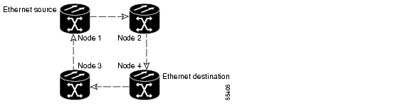
This appendix provides an in-depth explanation of ONS 15454 circuit routing and VT tunneling in mixed protection or meshed environments, such as the one shown in Figure A-1. For circuit creation and provisioning procedures, see Chapter 6, "Circuits and Tunnels."

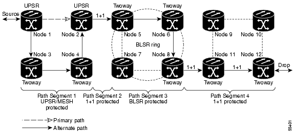
Figure A-1 Multiple protection domains

Automatic Circuit Routing

If you select automatic routing during circuit creation, Cisco Transport Controller (CTC) routes the circuit by dividing the entire circuit route into segments based on protection domains. For unprotected segments of protected circuits, CTC finds an alternate route to protect the segment in a virtual UPSR fashion. Each path segment is a separate protection domain, and each protection domain is protected in a specific fashion (virtual UPSR, BLSR, or 1+1).

Circuit Routing Characteristics

The following list provides principles and charactistics of automatic circuit routing:

Circuit routing tries to use the shortest path within the user-specified or network-specified constraints. VT tunnels are preferable for VT circuits because VT tunnels are considered shortcuts when CTC calculates a circuit path in path-protected mesh networks.

If you do not choose Fully Path Protected during circuit creation, circuits may still contain protected segments. Because circuit routing always selects the shortest path, one or more links and/or segments may have some protection. CTC does not look at link protection while computing a path for unprotected circuits.

Circuit routing will not use links that are down. If you want all links to be considered for routing, do not create circuits when a link is down.

Circuit routing computes the shortest path when you add a new drop to an existing circuit. It tries to find a shortest path from the new drop to any nodes on the existing circuit.

If the network has a mixture of VT-capable nodes and nodes that are not VT capable, depending on the route found, CTC will automatically force creation of a VT tunnel. Otherwise, CTC asks you whether a VT tunnel is needed.

Bandwidth Allocation and Routing

Within a given network, CTC will route circuits on the shortest possible path between source and destination based on the circuit attributes, such as protection and type. CTC will consider using a link for the circuit only if the link meets the following requirements:

The link has sufficient bandwidth to support the circuit

The link does not change the protection characteristics of the path

The link has the required time slots to enforce the same time slot restrictions for BLSR

If CTC cannot find a link that meets these requirements, it displays an error

The same logic applies to VT circuits on VT tunnels. Circuit routing typically favors VT tunnels because, based on topology maintained by circuit routing, VT tunnels are shortcuts between a given source and destination. If the VT tunnel in the route is full (no more bandwidth), CTC asks whether you want to create an additional VT tunnel.

Secondary Sources and Drops

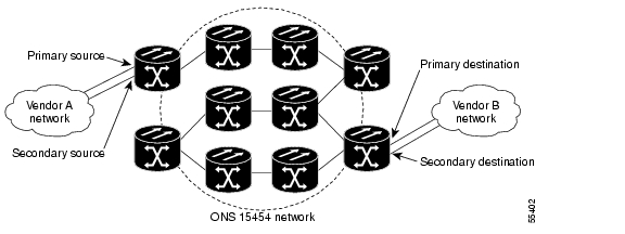
CTC supports secondary sources and drops. Secondary sources and drops typically interconnect two "foreign" networks, as shown in Figure A-2. Traffic is protected while it goes through a network of ONS 15454s.

Figure A-2 Secondary sources and drops

Several rules apply to secondary sources and drops:

CTC does not allow a secondary destination for unidirectional circuits because you can always specify additional destinations (drops) after you create the circuit

Primary and secondary sources should be on the same node

Primary and secondary destinations should be on the same node

The sources and drops cannot be DS-3, DS3XM, or DS-1 based STS-1s or VTs

Secondary sources and destinations are permitted only for regular STS/VT connections (not for VT tunnels and multicard EtherSwitch circuits)

For point-to-point (straight) Ethernet circuits, only SONET STS endpoints can be specified as multiple sources or drops

For bidirectional circuits, CTC creates a UPSR connection at the source node that allows traffic to be selected from one of the two sources on the ONS 15454 network. If you check the Fully Path Protected option during circuit creation, traffic is protected within the ONS 15454 network. At the destination, another UPSR connection is created to bridge traffic from the ONS 15454 network to the two destinations. A similar but opposite path exists for the reverse traffic flowing from the destinations to the sources.

For unidirectional circuits, a UPSR drop-and-continue connection is created at the source node.

Manual Circuit Routing

Routing circuits manually allows you to:

Choose a specific path, not just the shortest path chosen by automatic routing

Choose a specific STS/VT on each link along the route

Create a shared packet ring for Multicard EtherSwitch circuits

Choose a protected path for Multicard EtherSwitch circuits, allowing virtual UPSR segments

CTC imposes the following rules on manual routes:

All circuits, except Multicard EtherSwitch circuits in a shared packet ring, should have links with a direction that flows from source to destination. This is true for Multicard EtherSwitch circuits that are not in a shared packet ring (see Figure A-1).

If you enabled Fully Path Protected, choose a diverse protect (alternate) path for every unprotected segment (see Figure A-3).

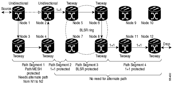
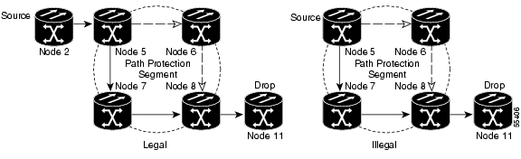
Figure A-3 Alternate paths for virtual UPSR segments

For Multicard EtherSwitch circuits, the Fully Path Protected option is ignored.

For a node that has a UPSR selector based on the links chosen, the input links to the UPSR selectors cannot be 1+1 or BLSR protected (see Figure A-4). The same rule applies at the UPSR bridge.

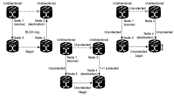
Figure A-4 Mixing 1+1 or BLSR protected links with a UPSR

Choose the links of Multicard EtherSwitch circuits in a shared packet ring to route from source to destination back to source (see Figure A-5). Otherwise, a route (set of links) chosen with loops is invalid.

Figure A-5 Ethernet shared packet ring routing

Multicard EtherSwitch circuits can have virtual UPSR segments if the source or destination is not in the UPSR domain. This restriction also applies after circuit creation; therefore if you create a circuit with UPSR segments, Ethernet node drops cannot exist anywhere on the UPSR segment (see Figure A-6).

Figure A-6 Ethernet and UPSR

VT Tunnels cannot be an endpoint of a UPSR segment. A UPSR segment endpoint is where the UPSR selector resides.

If Fully Path Protected is chosen, CTC verifies that the route selection is protected at all segments. A route can have multiple protection domains with each domain protected by a different mechanism.

The following tables summarize the available node connections. Any other combination is invalid and will generate an error.

Table A-1 Bidirectional STS/VT/Regular Multicard EtherSwitch/Point-to-Point (straight) Ethernet Circuits 

# of Inbound Links
# of Outbound Links
# of Sources
# of Drops
Connection Type

-

2

1

-

UPSR

2

-

-

1

UPSR

2

1

-

-

UPSR

1

2

-

-

UPSR

1

-

-

2

UPSR

-

1

2

-

UPSR

2

2

-

-

Double UPSR

2

-

-

2

Double UPSR

-

2

2

-

Double UPSR

1

1

-

-

Two Way

0 or 1

0 or 1

Ethernet Node Source

-

Ethernet

0 or 1

0 or 1

-

Ethernet Node Drop

Ethernet


Table A-2 Unidirectional STS/VT Circuit

# of Inbound Links
# of Outbound Links
# of Sources
# of Drops
Connection Type

1

1

-

-

One way

1

2

-

-

UPSR Head End

-

2

1

-

UPSR Head End

2

-

-

1+

UPSR drop and continue


Table A-3 Multicard Group Ethernet Shared Packet Ring Circuit

# of Inbound Links
# of Outbound Links
# of Sources
# of Drops
Connection Type
At intermediate nodes only

2

1

-

-

UPSR

1

2

-

-

UPSR

2

2

-

-

Double UPSR

1

1

-

-

Two way

At source or destination nodes only

1

1

-

-

Ethernet


Table A-4 Bidirectional VT Tunnels 

# of Inbound Links
# of Outbound Links
# of Sources
# of Drops
Connection Type
At intermediate nodes only

2

1

-

-

UPSR

1

2

-

-

UPSR

2

2

-

-

Double UPSR

1

1

-

-

Two way

At source nodes only

-

1

-

-

VT tunnel end point

At destination nodes only

1

-

-

-

VT tunnel end point


Although virtual UPSR segments are possible in VT Tunnels, VT tunnels are still considered unprotected. If you need to protect VT circuits either use two independent VT tunnels that are diversely routed or use a VT tunnel that is routed over only 1+1 or BLSR (or a mix) links.

Constraint-Based Circuit Routing

When you create circuits, you can choose Fully Protected Path to protect the circuit from source to destination. The protection mechanism used depends on the path CTC calculates for the circuit. If the network is comprised entirely of BLSR and/or 1+1 links, or the path between source and destination can be entirely protected using 1+1 and/or BLSR links, no PPMN (virtual UPSR) protection is used.

If virtual UPSR (PPMN) protection is needed to protect the path, set the level of node diversity for the PPMN portions of the complete path on the Circuit Creation dialog box:

Required—Ensures that the primary and alternate paths of each PPMN domain in the complete path have a diverse set of nodes.

Desired—CTC looks for a node diverse path; if a node diverse path is not available, CTC finds a link diverse path for each PPMN domain in the complete path.

Don't Care—Creates only a link diverse path for each PPMN domain

When you choose automatic circuit routing during circuit creation, you have the option to require and/or exclude nodes and links in the calculated route. You can use this option to:

Simplify manual routing, especially if the network is large and selecting every span is tedious. You can select a general route from source to destination and allow CTC to fill in the route details.

Balance network traffic; by default CTC chooses the shortest path, which can load traffic on certain links while other links are either free or less used. By selecting a required node and/or a link, you force the CTC to use (or not use) an element, resulting in more efficent use of network resources.

CTC considers required nodes and links to be an ordered set of elements. CTC treats the source nodes of every required link as required nodes. When CTC calculates the path, it makes sure the computed path traverses the required set of nodes and links and does not traverse excluded nodes and links.

The required nodes and links constraint is only used during the primary path computation and only for PPMN domains/segments. The alternate path is computed normally; CTC uses excluded nodes/links when finding all primary and alternate paths on PPMNs.


hometocprevnextglossaryfeedbacksearchhelp

Posted: Fri Feb 22 16:27:46 PST 2008
All contents are Copyright © 1992--2008 Cisco Systems, Inc. All rights reserved.
Important Notices and Privacy Statement.