|
|

Table Of Contents
5.3.1 Configuring ONS 15305 SDH Port Structure (Channelization)
5.3.2 Modifying or Removing ONS 15305 SDH Port Structure
5.3.3 Setting and Reading Path Trace Identifiers
5.3.4 Monitoring SDH Port Performance
5.3.5 Enabling the SDH Port to Carry Traffic and Report Alarms
5.3.6 ONS 15305 SDH Port Synchronization Quality Output Signaling
5.3.7 Use the SDH Port as a Synchronization Source Input
5.3.8 Carry Management Traffic DCC by SDH Port Channels
5.4.1 Setting the Port Mode for ONS 15305
5.4.2 Setting a Loop in an ONS 15305 PDH Port
5.4.3 Setting a Loop in an ONS 15302 PDH port
5.4.4 Releasing a Loop in a PDH Port
5.4.5 Assign VC12s in ONS 15302
5.4.6 Setting and Reading Path Trace Identifiers
5.4.7 Monitoring PDH Port VC-n Performance
5.4.8 Monitoring PDH E1 Port Performance
5.4.9 Enabling the PDH Port to Carry Traffic and Report Alarms
5.4.10 Cross-connect the ONS 15305 PDH Port to another Port
5.5.1 ONS 15305 - LAN Port Attributes
5.5.2 ONS 15302 LAN Port Attributes
5.6 ONS 15305 SDH Cross-Connection Management
5.6.1 SDH Layer Network and Cross Connections
5.6.2 Open the Cross Connection GUI
5.6.3 Browsing Existing Cross-connections
5.6.4 Setting up Cross-connections
5.6.5 Modifying Cross Connections
5.6.6 Protecting Cross Connections
5.6.7 Deleting Cross-connections
5.6.8 Advanced Cross-connection Operations
5.7 ONS 15305 SDH Protection Management
5.7.6 Legal combinations of SNCP and MSP
5.7.7 SubNetwork Connection Protection
5.8 ONS 15302 SDH Protection Management
5.8.1 Multiplex Section Protection
5.9 Ethernet Standardized Mapping
5.9.2 GFP Alarm and Event Conditions
5.9.3 GFP Performance Monitoring
5.9.4 VCAT - Virtual Concatenation
5.9.6 LCAS- Link Capacity Adjustment Scheme
5.9.7 VCAT and LCAS Alarms and Events
5.10 VCAT and LCAS Configuration Modes
5.10.1 VCAT with LCAS Enabled- Mode 1
5.10.2 VCAT Without LCAS Enabled- Mode 2
5.11 Administrative Bandwidth for VCAT
5.11.1 Bandwidth for uni-directional VCAT
5.12 Circuit Protection for VCAT
5.12.1 CirCuit Protection For Uni-directional Modes For ONS 15305
5.12.2 Circuit proTection For Symmetrical VCAT
5.13 Establish a standardized Mapping With CEC
5.14 Bi-directional VCAT Without LCAS
5.15 ONS 15305 Proprietary NxVC-12 EoS Mapping
5.15.2 WAN to SDH mapping- Custom GUI
5.15.3 Add Initial WAN Port Capacity
5.15.4 Modify WAN Port Capacity
5.15.6 Modifying Protection Parameters of the WAN Port
5.15.7 Commanding WAN Port Protection Switch
5.15.8 Setting Path Trace Identifiers for WAN Port
5.15.9 Reading Path Trace Identifiers for WAN Port
5.15.10 Monitoring WAN Port Performance
5.15.11 Advanced WAN Port Operations
5.16 ONS 15302 Proprietary NxVC-12 EoS Mapping
5.16.1 WAN ports and the Mapping
5.16.2 Differences between ONS 15305 and ONS 15302
5.16.4 Increase Capacity in the SDH Server Layer
5.16.5 Decrease Capacity in the SDH Server Layer
5.16.6 Setting Path Trace Identifiers for WAN Port
5.16.7 Reading Path Trace Identifiers for WAN Port
5.16.8 Monitoring WAN Port Performance
5.16.9 Advanced WAN Port Operations
Traffic Port Management
5.1 About Port Types
One of the advantages of the ONS 15305 compared to other products is the possibility to equip it with a number of different port types. Some ports are part of the base unit and always present, (management port, AUX ports, alarm input and output ports). The alarm ports and auxiliary port cannot be created or deleted.
See also the "4.2.1 Manage the Management Interfaces of the Network Element" section on page 4-2, the "Alarm Ports" section on page 4-35, and the "AUX Port - ONS 15305" section on page 4-36.
Traffic ports are available on replacable traffic modules. When a slot is configured to support a specific traffic module the ports of the traffic module is automatically created as described in the "4.11 Manage Slots on ONS 15305" section on page 4-85.
In this chapter we concentrate on the configuration of the traffic ports. The chapter is organized according to the following structure:
•
SDH ports
•
•
•
5.2 Selecting a Traffic Port
Traffic ports are always located on a traffic module in slot 1 to 4. In ONS 15305 managed objects for modules and ports are available when the slot is configured for a specific module type. This section describes how to select a traffic port regardless of the traffic it carries.
Step 1
Step 2
Step 3
The physical port usually carries a set of protocols (for example SDH) and the protocols are available from the management tree.5.3 SDH Ports
Note
5.3.1 Configuring ONS 15305 SDH Port Structure (Channelization)
By default the SDH ports are unstructured (or not-channelized) when created. Only the SDH port, rs, ms and aug1 managed objects are available. In this state the paths inside the STM-N frame cannot be terminated nor cross-connected, but the port can be used as a protection port in an MSP protection scheme and as a synchronization source candidate. It can also carry DCN traffic in the DCC channels.
The motivation for structuring an SDH port is to identify the paths in the STM-N frame and make them available for cross-connection. As you structure the port it will fan out in the management tree, showing termination points that are now available for cross-connection.
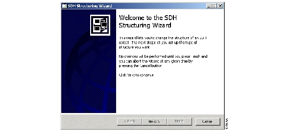
5.3.1.1 SDH Structuring Wizard
This wizard lets you to change the structure of an SDH object. The next steps let you set up the type of structure you want.
Figure 5-1 Open The Structuring Wizard
Step 1
Step 2
Figure 5-2 SDH Structuring Wizard
No changes will be performed until you press Finish and you can abort the wizard at any given time by pressing the Cancel button.
Structure Information displays the current SDH structure. The decisions you make in subsequent steps will affect this structure
Structure Type; Select the type of SDH structure you want.
Completing the Structure SDH Structuring Wizard; This step lists all the changes that will be performed when you press Finish.
The following sections show how to perform structuring using the Management Tree.
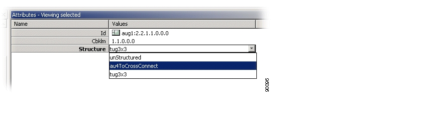
5.3.1.2 AU4 Termination Points for Cross-connection
Step 1
Step 2
Step 3
Figure 5-3 Select the Aug1 Managed Object
Step 4
Figure 5-4 Set the Structure Attribute
Step 5
Step 6
5.3.1.3 Tu3 Termination Points for XC
Tu3 termination points for XC.
Step 1
Step 2
Step 3
Step 4
Step 5
Step 6
5.3.1.4 Tu12 Managed Objects for XC
Tu12 managed objects for XC.
Step 1
Step 2
Step 3
Step 4
5.3.2 Modifying or Removing ONS 15305 SDH Port Structure
It is also possible to modify or remove the structure of an SDH port when the involved termination points are not cross-connected.
5.3.2.1 Modify between Tu12 and Tu3 Objects
Modify between Tu12 and Tu3 objects.
Step 1
Step 2
5.3.2.2 Modify between Au4 and Tu3 or Tu12 Objects
How to modify between Au4 and Tu3 or Tu12 objects.
Step 1
Step 2
Step 3
Note
Note
5.3.3 Setting and Reading Path Trace Identifiers
Path Trace are available at two levels in the SDH port:
•
•
5.3.3.1 Set or Read RS Path Trace Identifiers
How to set or read RS path trace identifiers:
Step 1
Step 2
Step 3
Step 4
•
Set to enable if TIM alarms should be reported when there is a mismatch between. PathTraceReceived and PathTraceExpected.
•
Enter a value for the path trace identifier that you expect to receive from the other side of the path.
•
Enter a value for the path trace identifier that you want to transmit to the other side of the path.
Step 5
•
The actual received path trace identifier from the other side of the link.
Step 6
5.3.3.2 Set or Read VC-4 Path Trace Identifiers
Note
Step 1
Step 2
Step 3
Step 4
Step 5
The attributes are the same as for RS path trace Step 4.
Step 6
Note
5.3.4 Monitoring SDH Port Performance
Performance Monitoring is available at three levels in the SDH port:
•
•
•
5.3.4.1 Read RS PM Counters
How to read rs pm counters
Step 1
Step 2
Step 3
Step 4
Step 5
•
•
Step 6
Step 7
•
•
5.3.4.2 Read MS PM Counters
How to read ms pm counters
Step 1
Step 2
Step 3
Step 4
5.3.4.3 Read VC-4 PM Counters
How to read VC-4 pm counters
Step 1
Step 2
Step 3
Step 4
Step 5
Step 6
5.3.5 Enabling the SDH Port to Carry Traffic and Report Alarms
By default the Administrative Status of the SDH port is set to disabled when the port is created. No alarms are reported before it is enabled.
Step 1
Step 2
Step 3
Note
- No alarms are reported towards the port.
- PM counters for the port will only count 0.
- If the port is part of MSP, the port will not be selected for traffic (unless this is a working port and the protecting port also is disabled or has SPI/RS/MS alarm).
Note
5.3.6 ONS 15305 SDH Port Synchronization Quality Output Signaling
STM-N signals are often used to carry synchronization information. A dedicated protocol is used to indicate the quality of the signal that is output from one SDH node to the next SDH node.
Step 1
Step 2
Step 3
Note
5.3.7 Use the SDH Port as a Synchronization Source Input
See the "4.6.4 Add Synchronization Source Candidate (T0 or T4)" section on page 4-44.
5.3.8 Carry Management Traffic DCC by SDH Port Channels
See the "4.3.2 DCC Configuration" section on page 4-17.
5.4 PDH Ports
ONS 15305 can be equipped with two different PDH port types:
•
•
ONS 15302 is equipped with E1 ports.)
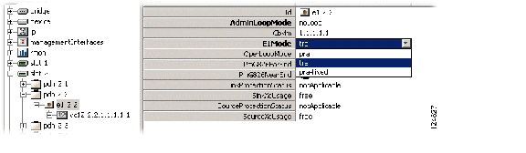
5.4.1 Setting the Port Mode for ONS 15305
How to set the port mode for ONS 15305:
Step 1
Step 2
Step 3
pra-fixed ( ISDN primary rate access with fixed timing)Figure 5-5 Set the E1 Mode Attribute
.
Step 4
Step 5
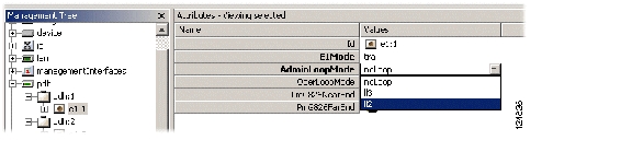
5.4.2 Setting a Loop in an ONS 15305 PDH Port
How to set a loop in an ONS 15305 PDH port
Step 1
Step 2
Step 3
Figure 5-6 Set Admin Loop Mode Attributes
Step 4
Note
5.4.3 Setting a Loop in an ONS 15302 PDH port
How to set a loop in an ONS 15302 PDH port
Step 1
Step 2
Step 3
Step 4
5.4.4 Releasing a Loop in a PDH Port
Release a loop in a PDH port:
Step 1
Step 2
Step 3
Step 4
Note
5.4.5 Assign VC12s in ONS 15302
Assign VC12s in ONS 15302:
Step 1
Step 2
You can use the WAN to SDH mapping window to view available VC12s with cbklm values.
Step 3
Figure 5-7 Assign VC 12 Por
t
5.4.6 Setting and Reading Path Trace Identifiers
Set and read path trace identifiers
Step 1
Step 2
Step 3
Step 4
The following attributes can be set:
•
Set to enable if TIM alarms should be reported when there is a mismatch between PathTraceReceived and PathTraceExpected.
•
Enter a value for the path trace identifier that you expect to receive from the other side of the path.
•
Enter a value for the path trace identifier that you want to transmit to the other side of the path.
Step 5
•
The actual received path trace identifier from the other side of the link.
Step 6
Note
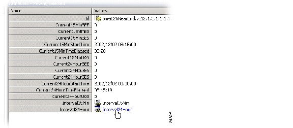
5.4.7 Monitoring PDH Port VC-n Performance
Monitor PDH port VC-n performance:
Step 1
Step 2
Step 3
Step 4
Step 5
•
•
Step 6
Step 7
•
•
Figure 5-8 Select Interval24Hour
Figure 5-9 Set Interval24Hour Attributes
5.4.8 Monitoring PDH E1 Port Performance
The E1 counters are based on CRC-4 counters for near end and E-bit counters for far end monitoring.
Defect criteria for near end is LOS-TX(Loss Of Signal), LOF-TX(Loss Of Frame) and module/slot alarms. For far end there are no alarms present to indicate any defects.
The valid flag for previous intervals and past 24 hours is set only when the port has been in PRA-mode during the whole period. For ports in TRA-mode, the PM counters can only be used to indicate SES/UAS due to LOS-TX or module/slot alarms.
Step 1
Step 2
Step 3
Step 4
•
•
Step 5
Step 6
•
•
5.4.9 Enabling the PDH Port to Carry Traffic and Report Alarms
By default the administrative status of the PDH port is set to disabled when the port is created. No traffic will pass through the port and no alarms are reported before it is enabled.
Step 1
Step 2
Step 3
Note
5.4.10 Cross-connect the ONS 15305 PDH Port to another Port
See the "ONS 15305 SDH Cross-Connection Management" section.
5.5 LAN Ports
About port attributes and their modification options.
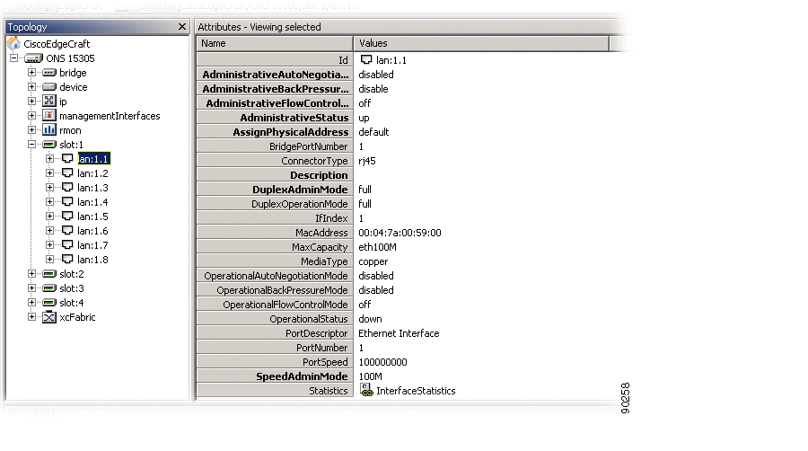
5.5.1 ONS 15305 - LAN Port Attributes
An ONS 15305 slot can for example be configured to carry an E100-WAN-8 module, see "4.11 Manage Slots on ONS 15305" section on page 4-85 for details.
Step 1
Step 2
Figure 5-10 LAN Port Attributes
:
These Attributes are modifiable:
•
disabled or enabled
•
disabled or enabled
•
on, off or auto negotiation
•
up, down or testing
•
reserve or default
•
string
•
none, half or full
•
not set, 10M, 100M or 1000M
Step 3
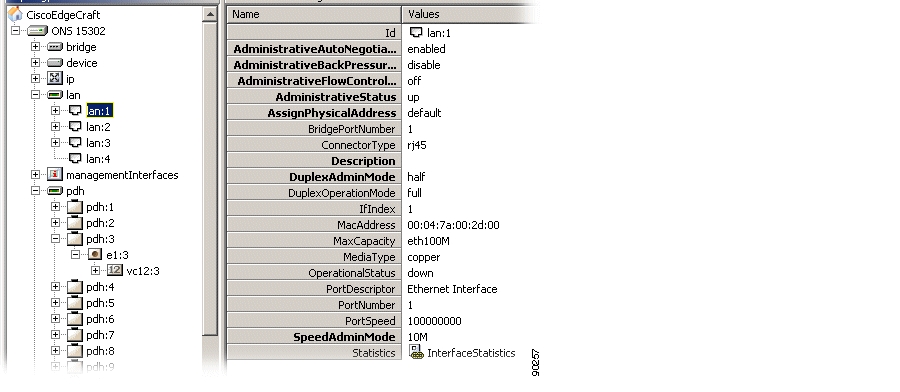
5.5.2 ONS 15302 LAN Port Attributes
The ONS 15302 is equipped with 4 LAN ports, Figure 5-11. For configuration of LAN ports see "ONS 15305 - LAN Port Attributes" section.
Figure 5-11 LAN Port Attributes - ONS 15302
5.6 ONS 15305 SDH Cross-Connection Management
The purpose of this section is to describe the tasks involved when managing cross connections between termination points on the network element.
The section involves management of the complete life cycle of a cross connection, including creation, presentation, modification, deletion and manual operation of the sub-network connection protection switch.
A cross connection is defined by its termination points. Only termination points with the same characteristic information can be cross-connected. The characteristic information of a termination point defines the format of the signal that can be transferred by this termination point. Format defines the capacity of the signal, for example TU-12 and VC-12 have the same characteristic information since they both have a 2 Mbps traffic capacity.
Unidirectional and bidirectional point to point cross connections with or without protection are supported.
The protection scheme supported by the first release of ONS 15305 is SNC/I, (inherent monitoring). ONS 15305 Release. 2.0 supports Non-intrusive monitoring SNC/N
The first part of this section gives a short introduction to SDH layers and cross connections which is meant to help the reader in understanding the requirements specified in this document. For further reading on SDH and cross connections, please see ITU-T Recommendations G-Series.
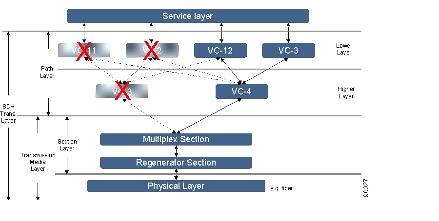
5.6.1 SDH Layer Network and Cross Connections
An SDH network has layered structure as depicted in Figure 5-12. The layers operate in a client/server based scenario. The service layer generates the bit streams that are to be carried across the SDH network. This layer is not part of SDH. The path layer is a virtual layer and can only be observed through a management system. It is in this layer that the cross connection management and structuring of the SDH ports are performed. The path layer works on containers.
Figure 5-12 SDH Layer Network
The ONS 15305 network element has support for VC-4 in the higher order layer and in the lower order layer VC-12 and VC-3.
5.6.1.1 SDH Port Structuring
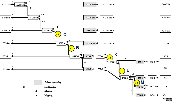
The multiplexing structure of the SDH ports determine which layers and their termination points that are available to be cross connected. The multiplexing structure for SDH in all layers are shown in Figure 5-13 (taken from ITU-T Recommendation G.707.) The C.B.K.L.M value determines the path trough the structure. The usage of the C.B.K.L.M value follows the rules defined in Table 5-1.
Only traffic on non-terminated containers called connection termination points can be cross connected, that means AU-4, TU-3, and TU-12. The other containers, VC-4, VC-3, and VC-12, represent trail termination points where the traffic can be read.
Figure 5-13 SDH Multiplexing Structure
The original illustration used in Figure 5-13, is found in ITU-T G.707/Y1322 (10/2000).
C.B.K.L.M Value Usage
Cross-Connection Management
Cross-connection management is the management of connectivity within the network element itself. Cross-connections (XC) are set up between connection termination points with the same characteristic information, for example cross connections between AU-4s, or between TU-3s, between VC-12 and TU-12, or between two VC-12s.
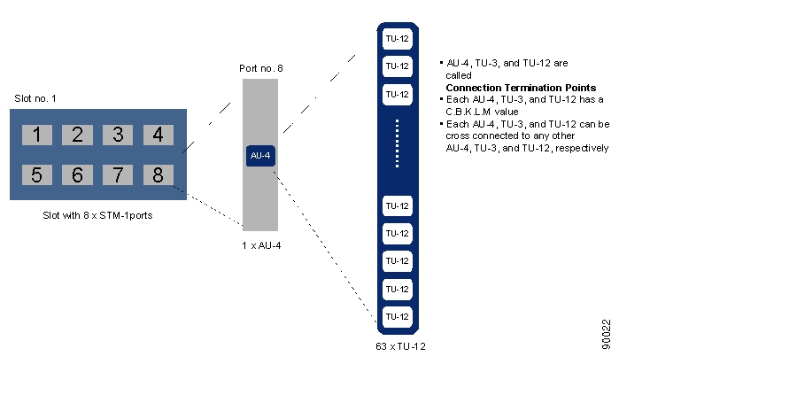
Figure 5-14 Slot - Port - CTP Relations
In ONS 15305 there are four slots that can hold an SDH module. The module can be of different types, that means, STM-1, STM-4, or STM-16. In this document the STM-1 module with 8 ports is used as an example.
In addition the ONS 15305 can have PDH modules with a number of E1 or E3 ports. The E1 and E3 ports have a corresponding VC-12 or VC-3, respectively. These VCs can be cross connected to termination points on the SDH modules or with each other.
5.6.1.2 Example
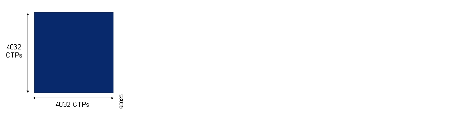
A slot with an 8 x STM-1 module has eight ports. Available CTPs on port no.8 in slot no. 1 are shown in Figure 5-14. There is one AU-4 on the port and depending on the structuring of the AU-4 container, there are 63 TU-12s, 3 TU-3s, or a combination of TU-12s and TU-3s since the TUG-3s can be structured independently, which can be cross connected. This means that in this single slot there are 8 x 63 = 504 CTPs (maximum) in the lower layer and 8 x 1 = 8 CTPs in the higher layer. And what are the possible CTPs to be cross connected to? If we assume that all four slots in this ONS 15305 are equipped with 8 x STM-1 modules there are 3 x 504 = 1512 possible choices for the connecting CTP in the lower layer and 8 x 3 = 24 in the higher layer. If an ONS 15305 is equipped with four STM-16 modules, each of these modules has 4 x 4 x 63 = 1008 TU-12 CTPs. This means that the cross connect matrix in the fabric has the dimension 4032 x 4032.
Figure 5-15 Largest Possible Cross Connect Matrix
This is a very large number of choices and impossible for a user to keep track of.
In addition there are several different types of cross connections:
•
•
•
•
All of these types can be with or without protection and uni-directional or bidirectional, Figure 5-16 to Figure 5-21.
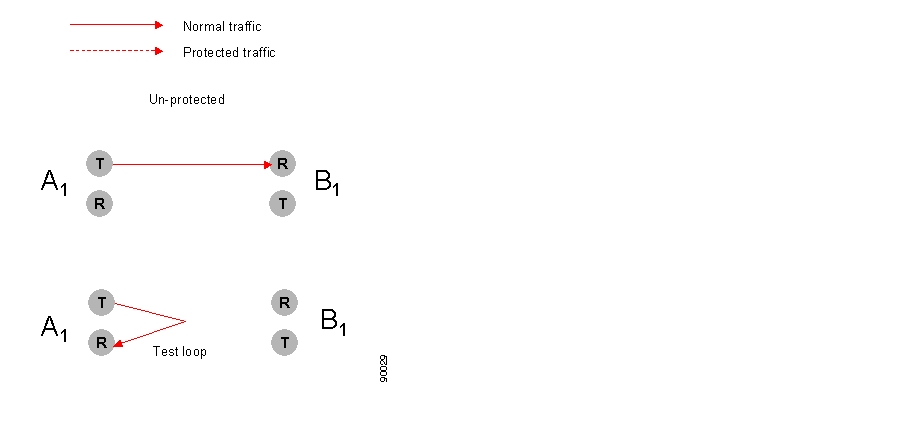
Figure 5-16 Unidirectional XC, Unprotected
Unprotected, unidirectional cross connects can be used for test loops, as illustrated in Figure 5-16.
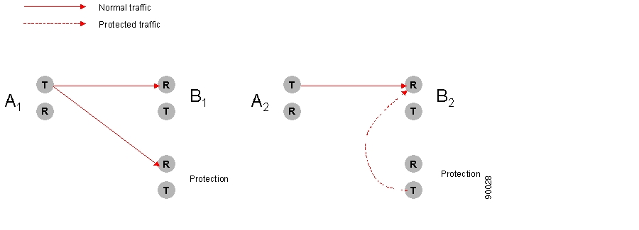
In Figure 5-17 protection has been set up for the termination point A1 and B2. The protected termination point A1 has no switching possibility since the cross connection is uni-directional, but termination point B2 has switching.
Figure 5-17 Uni-directional XC, Protected
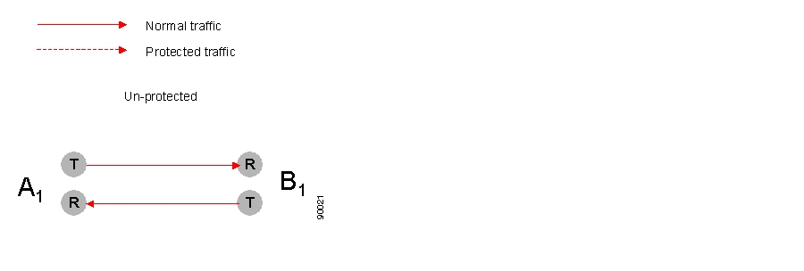
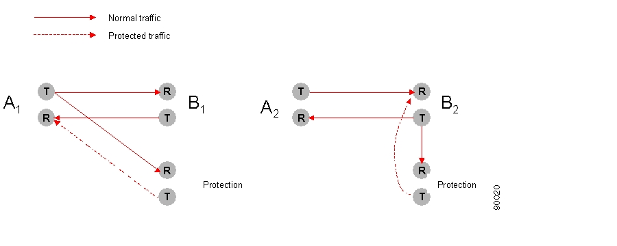
The bidirectional, unprotected cross connection is depicted in Figure 5-18. For bidirectional cross- connections all termination points have switching possibilities when protected. In Figure 5-19 the termination points A1 and B2 are protected, that means A1 can choose to receive from either B1 or the protection and B2 can switch between A2 or the protection.
Figure 5-18 Bidirectional XC, Unprotected
Figure 5-19 Bidirectional, Protected
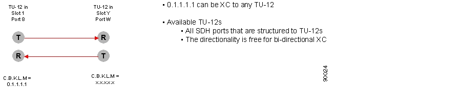
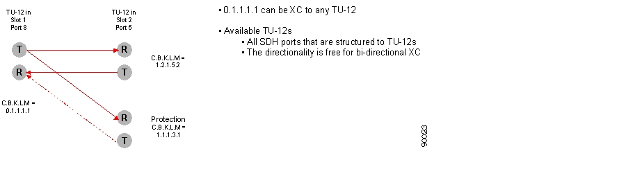
Figure 5-20 Example of Bidirectional, Unprotected, Point-to-point XC
Figure 5-21 Example of Bidirectional, Protected, Point-to-point XC
Examples of an unprotected, bidirectional, point-to-point cross connect and a protected, bidirectional, point-to-point cross connect are given in Figure 5-20 and Figure 5-21, respectively.
5.6.1.3 XC Fabric
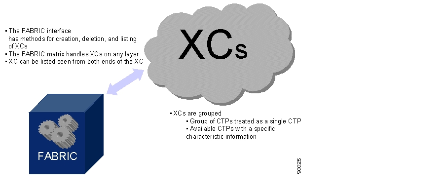
The connection management is taken care of by a Fabric as depicted in Figure 5-22. The Fabric has an interface that offers a set of methods that helps you in the cross connection management tasks on any layer. The Fabric can create, delete, and modify cross connections. It has several options for listing of XCs, for example, all XCs with the same characteristic information, all available CTPs on one port of a specific characteristic information. A third possible listing of CTPs can be a pre-defined grouping of points. A user might be indifferent to which specific CTP that is used in a XC as long as it a member of a specific group of CTPs. The system will choose an arbitrary CTP in the group. This will simplify the selection of CTP for you.
Figure 5-22 XC Fabric
5.6.2 Open the Cross Connection GUI
You have two possible choices for opening of the Cross Connection GUI.
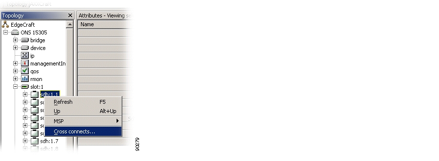
Step 1
Figure 5-23 Select Cross Connect
or;
Step 2
Figure 5-24 Select SDH Port Cross Connect
The system presents the cross-connection GUI with the relevant data from the selected managed object in the management tree.
The cross-connection GUI allows you to filter the selection based on predefined set of queries.
5.6.2.1 Cancelling a query
Queries in progress can be cancelled by selecting the Stop operation from the tool bar or the menu.
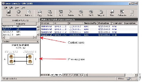
5.6.2.2 Cross-connection GUI - Overview
Figure 5-18 displays the cross-connection screen.
Figure 5-25 Cross-connection GUI - Overview
5.6.3 Browsing Existing Cross-connections
Cross connections can be browsed in the cross connect window in the following manner:
5.6.3.1 Browsing all Cross-connections
To browse all:
Step 1
Step 2
Note
5.6.3.2 Browsing Cross-connections of a Port
Browse a port:
Step 1
Step 2
A list of all cross-connections to and from the port is shown.
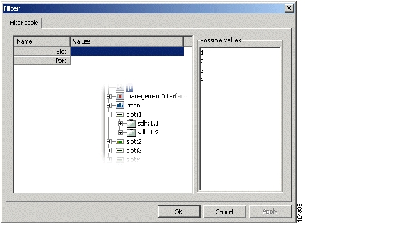
5.6.3.3 Filtering the Content of the Cross-connection List
To filter the content of the cross connection list, follow these steps:
Step 1
Step 2
Step 3
Figure 5-26 Example of Filtering Criteria - Cross-connections
.
Step 4
The cross-connects window shows only cross-connections where at least one of the termination points are included in the filtering criteria.
A filter icon is displayed in the status bar of the window to indicate that the filter is active.
5.6.3.4 Refreshing the Cross-connect Window
Refreshing the window will refresh the available TP list and cross-connection list based on the last operations performed by the local user of Cisco Edge Craft.
Step 1
5.6.4 Setting up Cross-connections
Cross connections can be se up between a number of different ports.
5.6.4.1 From a 2 Mbps E1 Port to a Timeslot in an SDH Port
Creating a cross-connection from a 2 Mbps E1 port to a timeslot in an SDH port (TU-12 termination point).
Step 1
Step 2
Figure 5-27 Select the VC/TU12 Tab
.
Step 3
Step 4
Note
Note
Note
Step 5
Step 6
Step 7
Step 8
Note
5.6.4.2 From a 45 Mbps E3 (T3) Port to a Timeslot in an SDH Port
Creating a cross-connection from a 45 Mbps E3 (T3) port to a timeslot in an SDH port (TU-3 termination point):
Step 1
Step 2
Figure 5-28 Select the VC/TU12 Tab
.
5.6.4.3 Creating a Pass-through Cross-connection
Creating a pass-through cross-connection from one SDH port to another SDH port:
Step 1
Step 2
5.6.5 Modifying Cross Connections
A cross-connection is a relationship between termination points and the relationship cannot be modified after it has been created.
It is not possible to modify the direction (bidirectional or unidirectional) of a cross-connection in the supported release of ONS 15305. The only parameter that can be modified is the description of the cross-connection.
Cross-connections can be protected after they have been created, Protecting Cross Connections.
5.6.6 Protecting Cross Connections
The A-end or B-end of a cross-connection can be protected by the SNC protection scheme when a cross-connection is being set up or after the cross-connection has been set up.
Note
Note
Step 1
Step 2
Step 3
Step 4
Step 5
Note
Note
Step 6
Step 7
Step 8
Step 9
Note
5.6.6.1 SNC Protection
How to set up a Sub network connection protection:
Step 1
Step 2
Step 3
Figure 5-29 Select Enabled Attributes
.
Step 4
Note
5.6.6.2 Modifying Protection Parameters of a Cross-connection
A-end or B-end of cross-connections are protected as described in the "Protecting Cross Connections" section. The SNC is then set up with a number of default parameters. The parameters can easily be modified.
Step 1
Step 2
Step 3
Step 4
Step 5
Step 6
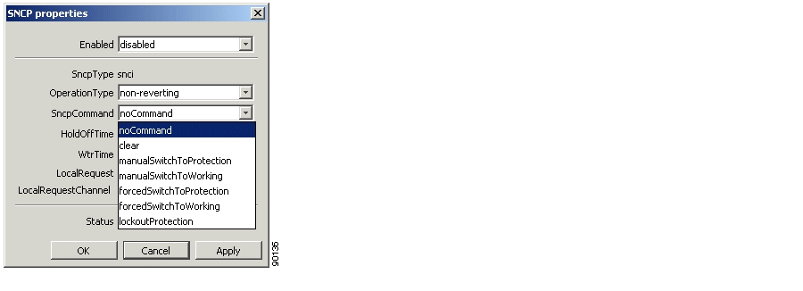
5.6.6.3 Commanding Cross-connection Protection Switch
The Cisco Edge Craft user can control the SNC protection switch by sending a command.
Step 1
Step 2
Step 3
Step 4
Figure 5-30 Select SNCP Command
.
Step 5
Depending on the priority of the command and current status of each channel, a switch can now take place for some or all selected cross-connections.
5.6.7 Deleting Cross-connections
A cross connection can be deleted in the following manner:
Step 1
Step 2
Step 3
Step 4
Step 5
5.6.8 Advanced Cross-connection Operations
For frequent users of Cisco Edge Craft, it is possible to make use of the enhanced editing facilities to speed up the configuration work.
5.6.8.1 Setting up of Multiple Cross-connections by Multiple Selection
You can set up multiple cross connections this way:
Step 1
Step 2
Step 3
Step 4
Step 5
Step 6
Step 7
Note
If you want to modify the A or B termination point the cross-connection must be deleted and created again.
If you want to modify the protection termination point the ProtectedTP must first be saved as none. Then the protection TP can be modified. Remember to set the ProtectedTP back to a.
Note
5.6.8.2 Setting up Multiple Cross-connections by Repeated Operations
Another way to set up multiple cross connections is to repeat an operation:
Step 1
Step 2
Step 3
Step 4
5.6.8.3 Entering Termination Points Manually
You can enter termination points manually like this:
Step 1
Step 2
Step 3
Step 4
Step 5
Step 6
Step 7
Note
5.7 ONS 15305 SDH Protection Management
The purpose of this section is to guide the user through management of the 1+1 linear multiplex section Protection (MSP) between two SDH ports.
5.7.1 Introduction
The section involves management of the complete life cycle of an MSP, including creation, presentation, modification, deletion and manual operation the MSP switch.
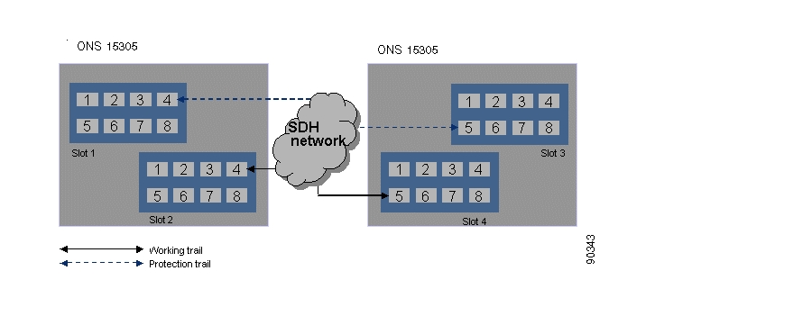
5.7.1.1 Multiplex Section Protection
Figure 5-31 1+1 MSP between two ONS 15305
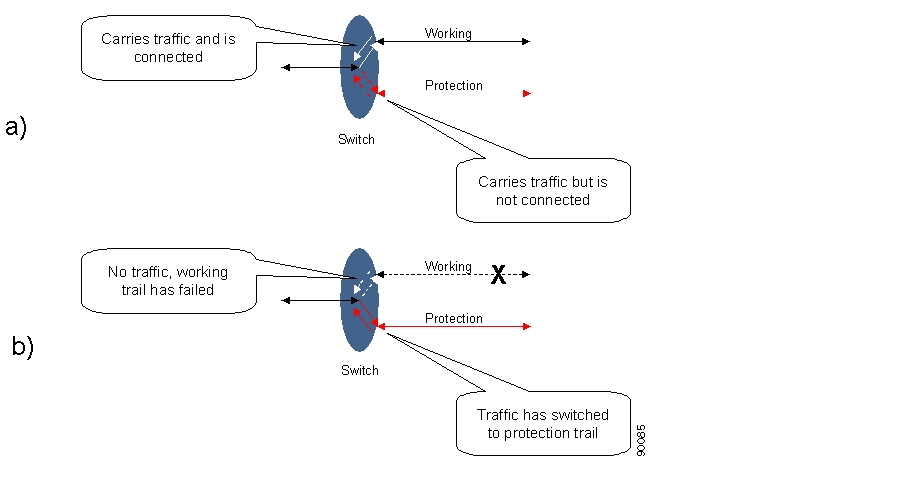
The 1+1 MSP provides protection of the SDH ports by replacing the supporting trail when it fails as illustrated in Figure 5-31. This is a 100% redundant protection scheme.
Figure 5-32 Protection Switching Scenarios
Both working and protection trails are enabled and the signal is bridged to both, Figure 5-32.
a.
b.
The switching has two different modes:
•
•
The time to wait before restoring the trail can be defined.
When switching either from or to protection, an event notification will be emitted.
5.7.2 Protect Section by MSP
MSP object for SDH port protection:
Step 1
Figure 5-33 Select SDH Port
.
Step 2
Step 3
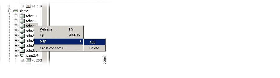
Figure 5-34 Select MSP Object
.
Step 4
Figure 5-35 Select Protection Port Attributes
Step 5
Working and Protection port must be selected from slot 1 and 2 or 3 and 4. Thus it is not possible to set up MSP protection with Working port from slot 1 and Protection port from slot 3. Working and Protection ports can be selected from the same slot.
A Protection port must be unstructured on the highest structurable level:
•
–
•
–
–
See the "Modifying or Removing ONS 15305 SDH Port Structure" section
The port must not be connected to a remote module.
Use default or fill in new values for the other attributes.
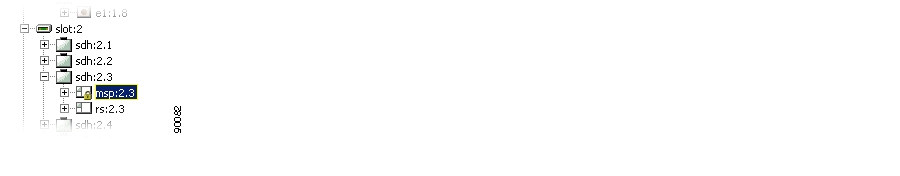
Step 6
The MSP scheme is created in ONS 15305 and starts working immediately. You will also see that the same msp object is now available under the protection port. You will also see that if the msp has the same Object identifier (for example 1.2.) as the parent SDH port, the port is a working port. If it has a number that is different from the parent SDH port (for example SDH port is 1.4 and msp is 1.2) it is a protection port for the SDH port with the same object identifier as the msp object.
5.7.3 Modify MSP
How to modify an MSP object:
Step 1
Step 2
Step 3
Step 4
Note
Note
5.7.4 Delete MSP
How to delete an MSP object:
Step 1
Step 2
Step 3
Note
Note
5.7.5 Command MSP Switch
How to set an MSP switch command:
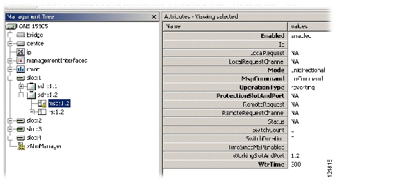
Step 1
Step 2
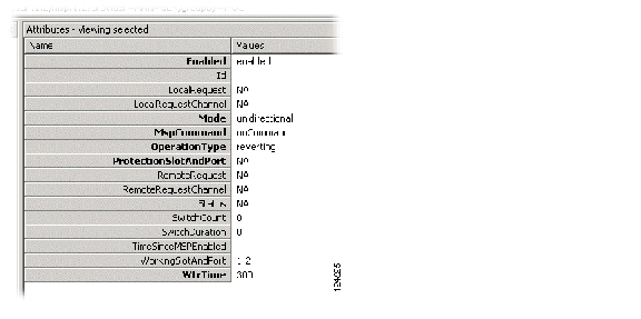
Step 3
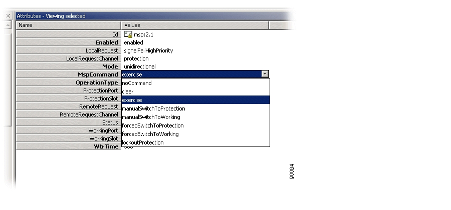
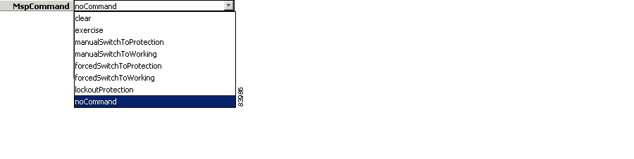
Figure 5-36 Select MspCommands Attribute
.
Step 4
Note
Note
Note
5.7.6 Legal combinations of SNCP and MSP
It is possible to use both SNCP and MSP in an ONS 15305 simultaneously, as long as the following is satisfied:
The protected SNCP entity can be part of an MSP protected port, but the working or protection entity can not, for example consider an STM-4 ring where some TU-12s are dropped off the ring and sent to an ONS 15302 via an STM-1 link. In this case, SNCP can be used in the ring, protecting the TU-12s to be dropped from the ring toward the ONS 15302. MSP can then be used for the STM-1 link to protect the traffic between the ONS 15305 and the ONS 15302. This is because the TU-12s that are dropped from the ring are the protected TU-12s, while the TU-12s in the ring are the working and protection TU-12s. Consequently, it is not possible to use MSP on the east or west links of the ring, since the TU-12s that are carried here are the working or protection part of the SNCP protected path's.
5.7.7 SubNetwork Connection Protection
SNCP is strongly related to the cross-connection that is protected in the network element. In Cisco Edge Craft SNCP related issues are handled from the cross-connections GUI.
Note
The resolution of the Hold-off timer is N x 100ms +/- 60 ms. That means for a 500 ms Hold-off timer, the real timer value can be any value between 440 ms and 560 ms. The Working, protection and protected parts of an SNCP protected path can be carried over different link rates. For example for an SNCP protected TU-12, the working TU-12 could be carried over an STM-16 link, while the protection TU-12 could be carried over an STM-4 link.5.7.7.1 Protect Connection by SNCP
See the "SNC Protection" section.
5.7.7.2 Modify SNCP
See the "Modifying Protection Parameters of a Cross-connection" section.
5.7.7.3 Command SNCP Switch
See the "Commanding Cross-connection Protection Switch" section.
5.8 ONS 15302 SDH Protection Management
The ONS 15302 offers 1+1 linear multiplex section protection (MSP).
5.8.1 Multiplex Section Protection
The protocol used for K1 and K2 (b1 to b5) is defined in ITU-T G.841, clause 7.1.4.5.1. The protocol used is 1+1 bidirectional switching compatible with 1:n bidirectional switching.
The operation of the protection switch is configurable as described in the "Modify MSP Parameters" section.
5.8.1.1 Modify MSP Parameters
How to modify MSP parameters.
Step 1
Figure 5-37 Select SDH1/MSP1 Attributes
Modifiable parameters:
•
Set to enabled or disabled.
•
Set to unidirectional or bidirectional.
•
Set one of the following.
•
Set to reverting or non-reverting.
•
Wait to restore time; number of seconds to wait before switching back to the preferred link after it has been restored (0,1....,12 minutes, default 5 min (300 seconds)).
Figure 5-38 Set MSP Command
Step 2
5.9 Ethernet Standardized Mapping
The Cisco network elements (ONS 15305 2.0 and ONS 15302 2.0) support two different modes of Ethernet over SDH (EOS) mapping:
•
See the "ONS 15305 Proprietary NxVC-12 EoS Mapping" section and the "ONS 15302 Proprietary NxVC-12 EoS Mapping" section.•
Note
This section describes EOS. The support of the different EOS modes are module dependent. WAN traffic modules support standardized mapping:
•
•
Presentation and modification of other WAN port parameters are described in the "Configuring ONS 15305 SDH Port Structure (Channelization)" section.
5.9.1 Introduction
The GFP, VCAT and LCAS standards provide a standardized (non-proprietary) way of allocating bandwidth for packet services through circuit switched networks such as SDH and SONET.
Note
These standards ensure inter-operability between mixed vendor transport networks, providing the required support for establishing packet (Ethernet) services over a circuit switched transport network. These are much required properties when extending packet switched GFP- Generic Framing Procedure
A main benefit of these standards compared to pure Ethernet/MPLS metro and national wide networks is that all the SDH benefits of network resilience provided by protection schemes (MSP, SNC) are maintained while still providing full Ethernet service interfaces at the endpoints of the transport network.
This also enables owners of existing SDH network infrastructure to adapt their existing networks to the mixed packet- and circuit switched client environments of today.
GFP is a generic format for encapsulating client-side data and control packets in order to enable controlled transport though an SDH network.
Note
GFP is a method used to encapsulate and map packet traffic in a way that is optimal for transport through circuit switched (line switched) networks such as SDH networks. The packaging conserves both client-side data and control information transparently through the switched network.
The packaging process performs the following:
•
•
•
•
•
5.9.2 GFP Alarm and Event Conditions
The following alarm and event conditions apply:
•
•
•
•
5.9.3 GFP Performance Monitoring
The following performance parameters apply:
•
•
•
•
A degrade alarm is available for the error type PMs, which are:
•
•
The error type PMs are handled in a similar way as the SDH performance parameters. The non error type PMs are handled in the same way as the RMON counters, the non error type PMs are:
•
•
5.9.4 VCAT - Virtual Concatenation
VCAT provides efficient bandwidth allocation for mapped packet traffic in the SDH network. Bandwidth is provided by assigning a group of SDH VCs to transport the GFP packet belonging to a client interface.
VCAT is a standardized end-to-end method for better bandwidth utilization of the SDH channels by allocating SDH bandwidth in increments in steps corresponding to increments of the SDH specific VC bandwidth (n*VC12, n*VC3, n*VC4 etc.).
This is a non-proprietary method similar to, but exceeding the Cisco proprietary Ethernet port bandwidth allocation by using several VC12 's to provide the required bandwidth, as described in the "Assign VC12s in ONS 15302" section.
VCAT allows using VC12's, VC3's, VC4's into VC groups, routing it through selectable AUs/TUs on different ports. Further, it compensates for delays caused by different routes through the network, and assures that end-pint traffic is assembled in the same sequence as it was disassembled at the entry-points.
5.9.5 VC Level for VCAT
The VC available VCAT VC levels depends on the Ethernet port:
Fast Ethernet
•
•
•
Gigabit Ethernet (ONS 15305)
•
•
The VC- level is individually configurable pr. mapper port. A mix of different VC- levels in one VC Group is not allowed and will result in an error.
Note
The mapping is flexible, and can be done to several SDH ports per Ethernet port within the mapping layer:
•
•
•
5.9.6 LCAS- Link Capacity Adjustment Scheme
LCAS provides on-the-fly bandwidth adjustments within a VCAT VC Group by allocating or de-allocating VCs from the VC Group. This is normally done to remove failing VCs from a VCAT VC Group, and provides both failure resilience and rapid restoration of traffic capacity.
VCAT works similar to Cisco proprietary mapping, but has more features, and is ITU-T standardized, allowing for inter operability with other vendors.
LCAS is a feature added to VCAT VC Groups, allowing for dynamic allocation and re-allocation of bandwidth in an operative Ethernet port.
LCAS is a standardized method to adjust the bandwidth of the packet transport channel through the SDH network on the fly. This bandwidth adjustment will typically be caused by the operative status (ok/fail) of the different VCs used in a VCAT Virtual Circuit group.
5.9.7 VCAT and LCAS Alarms and Events
The following alarms are related to the VCAT and LCAS:
5.10 VCAT and LCAS Configuration Modes
The two different operation modes for the VCAT and LCAS functionality are:
•
•
5.10.1 VCAT with LCAS Enabled- Mode 1
VCAT with LCAS enabled is always uni-directional, which enables the possibility to have different capacity in each direction, but requires a separate cross connect/ capacity setup in each direction.
The connections will however very often be bi-directional, and to reduce the number of configuration steps it is possible to enables the following parameter:
•
If symmetric capacity is enabled the VC Group is automatically set up with the same capacity in each direction, but the symmetric capacity consists of two uni-directional connections. With the symmetric mode disabled the capacity of the VC Group will need to be configured separately in each direction.
5.10.2 VCAT Without LCAS Enabled- Mode 2
When VCAT is used without LCAS, there is no mechanism for removing of a faulty VC container in a VCG group. To solve this problem the network element has, in addition to the standard mode, a proprietary mode.
The following configurations are available in mode 2:
•
•
If bidirectional mode is enabled, the cross connections should not be uni-directional, but bi-directional. In addition RDI signalling is enabled. A faulty container in a VC Group is removed based upon the VC alarm condition or based upon RDI signalling (similar to Cisco proprietary mapping). This will allow a VC Group to continue operation even if the VCG has a failed member. This configuration mode is proprietary.
5.11 Administrative Bandwidth for VCAT
Network elements use the administrative bandwidth as a separate defined parameter, independently of the actual assignment of TPs. The administrative bandwidth is used as a notification in case the actual (operative) bandwidth differs from the administrative bandwidth. In ONS 15302, the administrative bandwidth is implicit when selecting the TPs to be mapped to the Ethernet port.
5.11.1 Bandwidth for uni-directional VCAT
The administrative bandwidth can be:
•
Same bandwidth downstream and upstream.•
Different defined bandwidths for the two directions.In uni- directional VCAT, the upstream (traffic flow towards the SDH ports) and downstream (traffic flow towards the Ethernet port) is routed in separate, uni-directional VC Groups. An ethernet port is a LAN port with Layer 1 or WAN port, expressed with character `x' in GUI.
The bandwidth is provided by mapping STM-n port(s) as termination points to the Ethernet port. The TPs will carry VCs in a VC Group assigned to the Ethernet port.
Note
5.11.1.1 Bandwidth for Bi-directional VCAT
The administrative bandwidth for bi- directional VCAT (Equivalent to Cisco proprietary mapping) is identical for both directions (transmit and receive), as the same TUs and AU's are used to provide the bandwidth.
Note
Bi-directional VCAT is a Cisco proprietary version of VCAT. It has symmetric capacity, and LCAS is not allowed.
To circumvent transmission failures due to the loss of VCs in a VC Group, RDI signaling is enabled, allowing the network element to automatically detect and remove faulty VCs in the VC Group. Failures will be indicated by error notifications and the reduction of the displayed operative capacity.
5.12 Circuit Protection for VCAT
If the network element contains an SDH cross connect, SNC/N or SNC/I is allowed when supported by the network element.
See the "Protecting a WAN Port" section and the "Protecting Cross Connections" section.
5.12.1 CirCuit Protection For Uni-directional Modes For ONS 15305
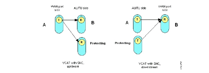
You define circuit protection when cross connecting Ethernet port channels to the SDH ports. Since the VCs are unidirectional, the VC termination can be both A-side (transmit) and B-side (receive), as illustrated in the figure below:
Figure 5-39
VCAT with SNC- Illustration
See the "Protecting Cross Connections" section.
5.12.2 Circuit proTection For Symmetrical VCAT
Circuit protection is the same for symmetrical VCAT and Cisco proprietary mapping modes.
5.13 Establish a standardized Mapping With CEC
You establish, modify and delete an Ethernet mapping at the endpoints of a Ethernet path through the network.
You can perform the standardized mapping in the Management Tree or in the WAN mapping GUI. Each mapping operation on an attribute in Management Tree results in a corresponding update of the associated network element attribute(s) in the WAN mapping GUI, see Figure 5-40.
Figure 5-40
standardized mapping- GUI overviews
5.13.0.1 BeFore You Start
•
•
The following procedures exemplifies standardized mapping types:
•
•
Note
5.13.0.2 Uni- directional VCAT with LCAS
You have selected the Ethernet mapping to be symmetrical uni- directional VCAT VC- level 3 with LCAS. ONS 15305 with Mapper module E100-WAN-8 as the Ethernet port (here: WANx) is used as an example.
Note
Step 1
Figure 5-41
Slot configuration- ONS 15305 example
Step 2
Figure 5-42
Ethernet port - VC Group view
Step 3
The appropriate structuring level is set to VCAT enabled port.Figure 5-43
VC Group concatenation- Example VC level
Step 4
LCAS is enabled for the VCAT enabled port, independent direction.Figure 5-44
Enable LCAS
Step 5
Step 6
Figure 5-45 Administrative Capacity- Symmetrical Uni- directional VCAT
Step 7
Figure 5-46 Operational Capacity- example asymmetrical capacity
Step 8
Step 9
Step 10
Step 11
Figure 5-47
WAN- to- SDH Mapping- LCAS Traffic Status
Alternative procedure:
Select one VC channel from VC group in Management Tree and choose Traffic as LCAS Channel Status. Repeat the operation for all VCs.Figure 5-48
LCAS traffic set for one VC Channel
Step 12
Step 13
A list of available VC termination points is presented.
Note
Step 14
The bandwidth is provided for distribution of the Ethernet port traffic through the STM port.
Note
Step 15
For procedure and scheme (SNC/I, SNC/N), see the "Protecting a WAN Port" section and the "Protecting Cross Connections" section.
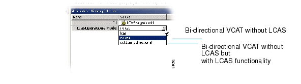
5.14 Bi-directional VCAT Without LCAS
With this VCAT configuration mode, each VC is used for traffic in both directions (equivalent to symmetrical uni- directional VCAT).
•
•
•
Figure 5-49
Lcas Operation Mode
Figure 5-50
Bi- directional VCAT- Example VC- level 12
A WAN port is mapped to the SDH network with the following parameters settings:
•
•
•
5.15 ONS 15305 Proprietary NxVC-12 EoS Mapping
The purpose of this section is to describe the tasks involved in assigning capacity from the SDH server layer to WAN ports with proprietary NxVC-12 EoS Mapping.
5.15.1 Introduction
The total assigned WAN capacity is made up of SDH channels.
One SDH channel is equivalent to a VC-12 (2 Mbps). Mapping to VC-3 and VC-4 is also supported. This section only describes the VC-12/TU-12 layer rate.
ONS 15305 supports Fast Ethernet module; Dual Optical LAN 1000Base-LX Module with Mapper, GigE-WAN-2 and
GigaBit Ethernet module: Octal LAN 10/100Base-TX Module with Mapper, E100-WAN-8.
The table below shows how many VC channels there are on each WAN port on the two modules.
The SDH channels can be from different SDH ports.
The WAN channels can be sub-network connection (SNC) protected. ONS 15305 supports the protection schemes SNC/I (inherent monitoring) and SNC/N (Non-Intrusive monitoring.
5.15.1.1 WAN Ports and the Mapping
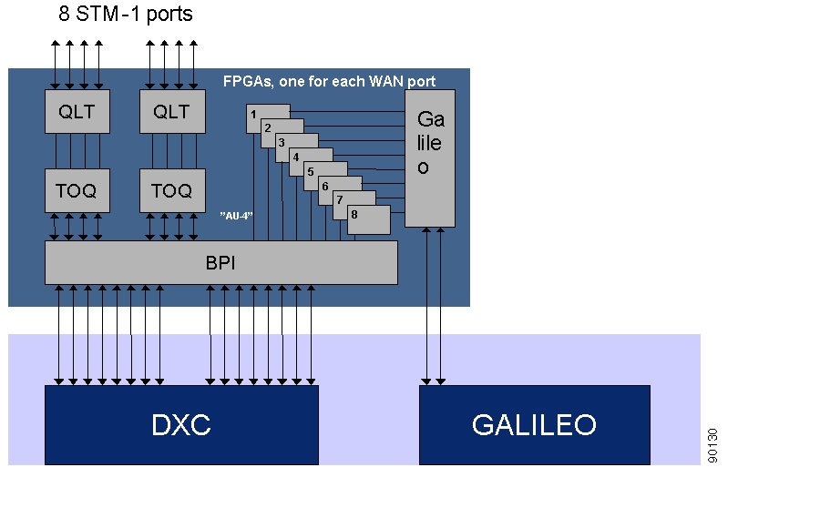
The eight WAN ports are located on the 8xSTM-1 module. They are connected to a Galileo switch, Figure 5-51. A WAN port has a maximum capacity of 100 Mbps.
Figure 5-51 The 8 x STM-1 Module with WAN Ports
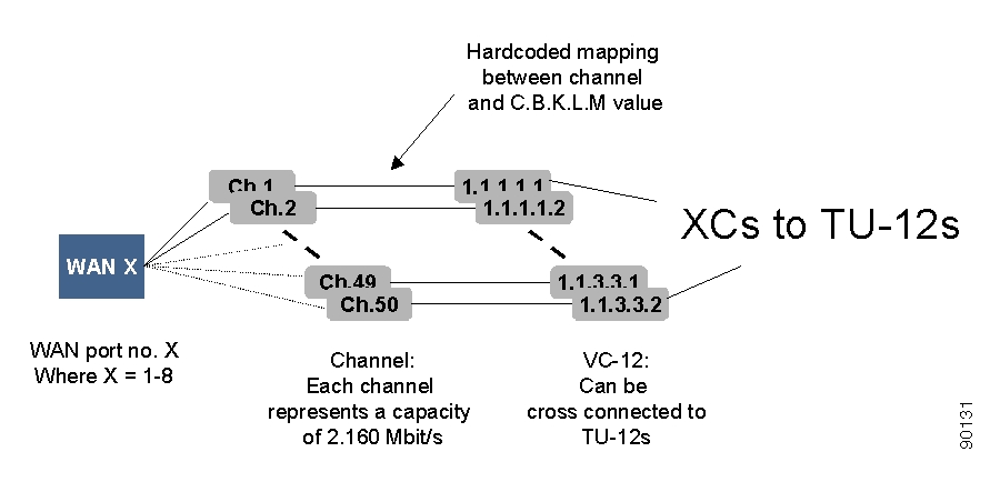
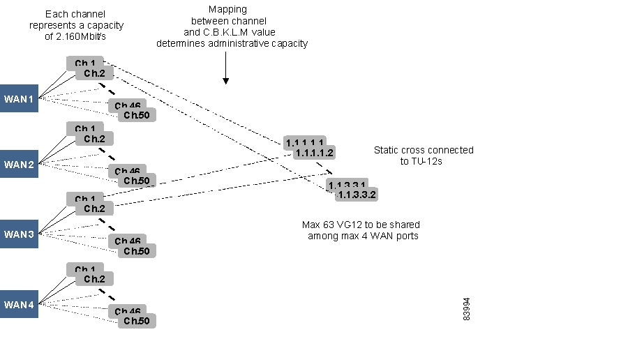
Figure 5-52 shows that the potential capacity of 100 Mbps is realized through 50 channels each able to carry 2.160 Mbps. The capacity of the WAN port is therefore decided by how many channels that are used for traffic.
A WAN port can be mapped to one STM-1 port, that means there are potentially 63 available VC-12s. Only the 50 first of these are used. These 50 channels have hard coded mapping to 50 VC-12 containers.
The C.B.K.L.M numbering is described in the "C.B.K.L.M Value Usage" section.
Figure 5-52 View of one WAN Port and its Logical View
The WAN VC-12s are cross connected to the available TU-12s on the SDH ports. All 50 WAN VC-12s are always available for cross connection. A WAN VC-12 always represents the termination point A in a cross connection and the connection is always bidirectional. The cross connection can be protected.
If a VC-12 (or channel) that is not cross connected exists inside the WAN capacity, the network element issues an alarm on the WAN VC-12 (unequipped alarm).
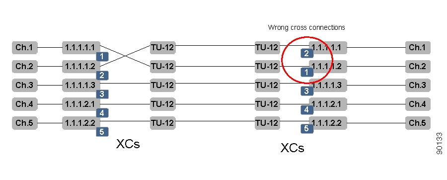
The order of the channels is essential and must be the same on both sides of a WAN connection, for example, containers sent from channel 1 must be received on channel 1. A sequence number is used to indicate the correct order of the VC-12 on the receiving side of a WAN connection between two ONS 15305. If the connection is not between two ONS 15305, the sequence number will be zero. A scenario where the cross connection between two TU-12s and two VC-12s in one ONS 15305 is wrong is illustrated in Figure 5-53.
Figure 5-53 Sequence Numbers for Correct Order of TU-12 to VC-12 Cross Connects.
Alarms and performance monitoring data are collected and reported for those VC-12s that are within the WAN capacity.
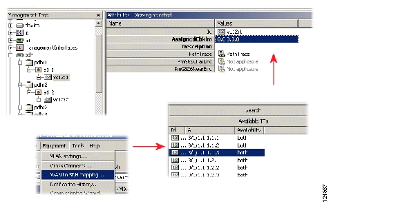
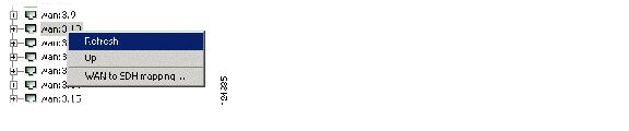
5.15.2 WAN to SDH mapping- Custom GUI
How to search, list and open terminations points for mapping
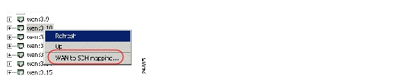
5.15.2.1 Open WAN to SDH Mapping
Step 1
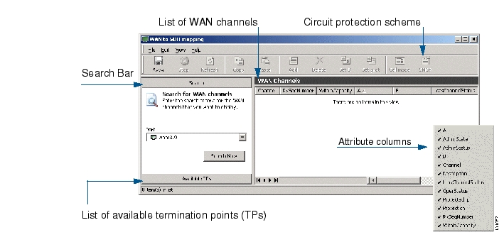
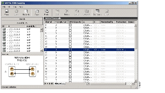
The list of WAN Channels will be empty.Figure 5-54 WAN- to- SDH Mapping- GUI Overview
A search bar is available for browsing Ethernet ports.
Step 2
Step 3
The list of WAN Channels will be displayed for the selected Ethernet port.
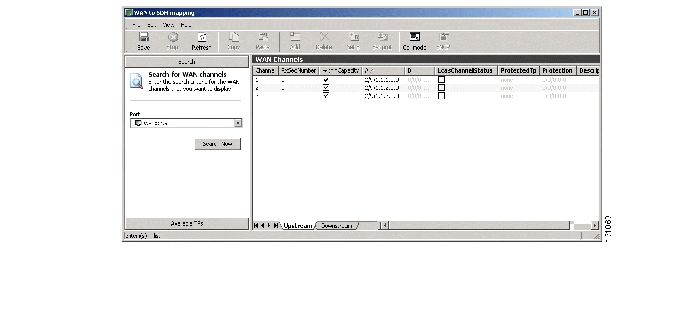
Figure 5-55 WAN port search- example uni- directional
5.15.2.2 List Available Termination Points
Step 4
A list of available STM- n ports is presented in accordance to VC- level.
Figure 5-56 WAN channels list- example VC/ TU 12
5.15.2.3 Cancelling a Query
Queries in progress can be cancelled by selecting the Stop operation.
5.15.3 Add Initial WAN Port Capacity
The addition of WAN port capacity is performed in a two step process.
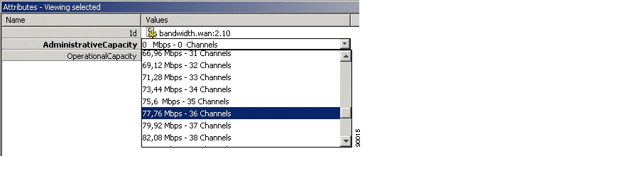
The first step is to set the administrative capacity of the WAN port. This will tell ONS 15305 how many of the 50 possible WAN channels to use for mapping into the SDH server layer.
Step 1
Step 2
Figure 5-57 Set Bandwidth
.
Step 3
Step 4
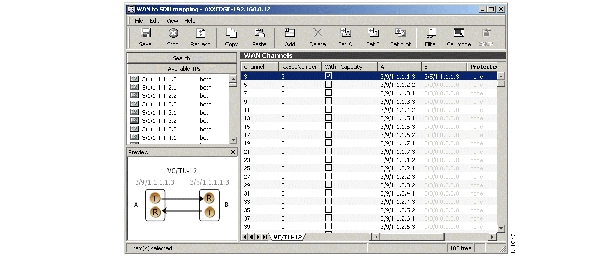
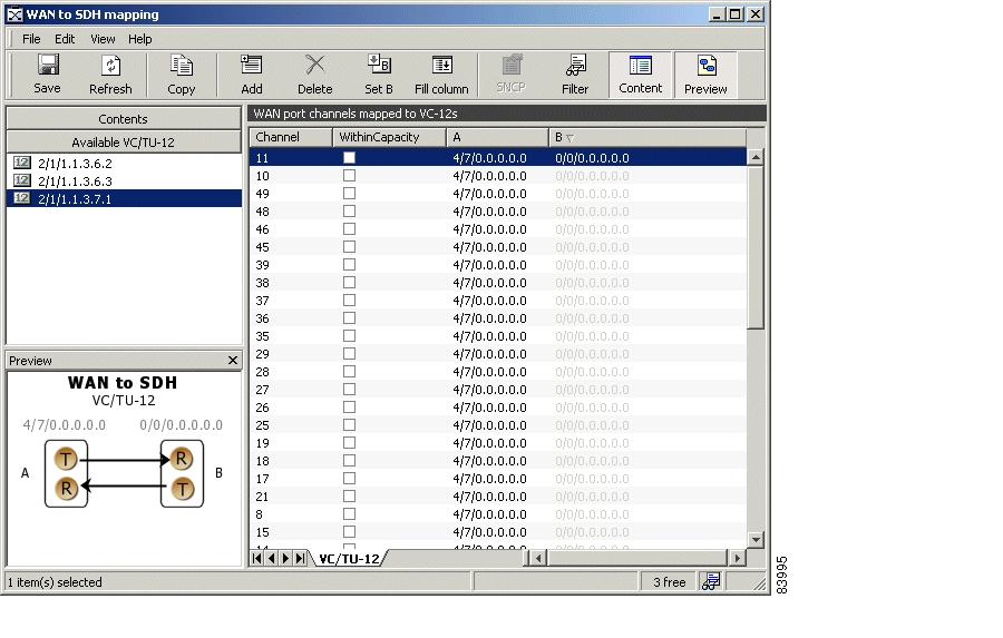
The next step is to cross-connect the WAN channels that are in use after setting the administrative capacity.
Step 5
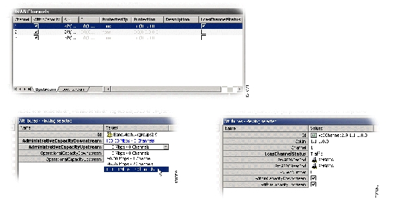
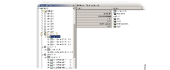
Figure 5-58 Select WAN Port Attributes
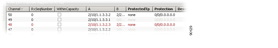
A list of all the WAN channels of the WAN port is shown. The list shows the static relation between each channel number and a VC12 object in the WAN port. The WithinCapacity attribute indicates if the channel is in use by the WAN channel (that means if it was included when setting the administrative capacity above).
Figure 5-59 Set WAN Port Attributes
.
Step 6
If it is not available select the Content button in the toolbar.
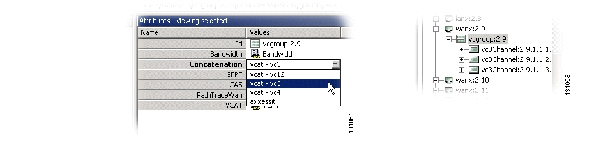
Step 7
Figure 5-60 Select Available VC/TU12
Note
Step 8
Step 9
Step 10
Step 11
Note
Note
5.15.4 Modify WAN Port Capacity
You can modify the WAN port capacity in the same way as you added the initial WAN capacity, "Add Initial WAN Port Capacity" section.
Step 1
Step 2
Step 3
Step 4
Step 5
A list of all the WAN channels of the WAN port is shown. The list shows the static relation between each channel number and a VC12 object in the WAN port. The WithinCapacity attribute indicates if the channel is in use by the WAN channel (that means if it was included when setting administrative capacity above).
Step 6
Step 7
5.15.4.1 Increasing Capacity in the SDH Server Layer:
Make sure the content panel is available in the left part of the window. If it is not available select the content button in the toolbar.
Step 1
Note
Step 2
Step 3
Step 4
Step 5
Step 6
5.15.4.2 Decreasing Capacity in the SDH Server Layer
Step 1
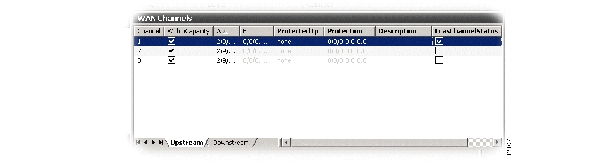
Step 2
Figure 5-61 Select WAN Channels
.
Step 3
Step 4
Note
5.15.5 Protecting a WAN Port
WAN ports can be protected by the SNC protection scheme in the VC12 or TU12 SDH layer. That means that the WAN channels (not necessarily all WAN channels of a WAN port) can have two different routes through the SDH server network, and that the receiving WAN channel selects the route with the best signal.
Step 1
Step 2
Figure 5-62 Select Protected Mode
Step 3
Step 4
Step 5
Note
Step 6
Step 7
Step 8
Step 9
Note
Step 10
Step 11
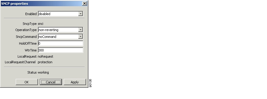
Step 12
Figure 5-63 Set SNCP Properties Enabled
.
Step 13
Note
5.15.6 Modifying Protection Parameters of the WAN Port
WAN ports are protected as described in "Protecting a WAN Port" section. The SNC is then set up with a set of default parameters. The parameters can easily be modified, Figure 5-64.
Step 1
Step 2
Step 3
Step 4
Step 5
Figure 5-64 Set SNCP Properties Protection
.
Step 6
5.15.7 Commanding WAN Port Protection Switch
The Cisco Edge Craft user can control the SNC protection switch by sending a command, Figure 5-65.
Step 1
Step 2
Step 3
Step 4
Step 5
Figure 5-65 Set SNCP Properties Command
.
Step 6
5.15.8 Setting Path Trace Identifiers for WAN Port
Path Trace parameters can be set for each channel (VC12) in the WAN port.
Step 1
Step 2
Step 3
•
Set to enable if TIM alarms should be reported for the WAN port when there is a mismatch between PathTraceReceived and PathTraceExpected.
•
Enter a value for the path trace identifier that you expect to receive from the other side of the WAN channels.
•
Enter a value for the path trace identifier that you want to transmit to the other side of the WAN channels.
Step 4
Note
5.15.9 Reading Path Trace Identifiers for WAN Port
Path trace parameters can be read for each channel (VC12) in the WAN port.
Step 1
Step 2
Step 3
Step 4
•
Set to enable if TIM alarms should be reported when there is a mismatch between PathTraceReceived and PathTraceExpected.
•
Enter a value for the path trace identifier that you expect to receive from the other side of the path.
•
Enter a value for the path trace identifier that you want to transmit to the other side of the path.
•
The actual received path trace identifier from the other side of the link.
Note
5.15.10 Monitoring WAN Port Performance
Follow the steps below to set up monitoring of WAN port performance.
Step 1
Step 2
Step 3
Step 4
•
•
Step 5
Step 6
•
•
5.15.11 Advanced WAN Port Operations
For frequent users of Cisco Edge Craft, it is possible to make use of the enhanced editing facilities to speed up the configuration work.
5.15.11.1 Selection and Insertion of Multiple Termination Points
Multiple termination points are selected like this:
Step 1
Step 2
Step 3
Step 4
Step 5
Step 6
Note
If you want to modify the B termination point the relation with the existing B termination point must first be deleted. Then a new termination point can be added.
If you want to modify the protection termination point the ProtectedTP must first be saved as none. Then the protection TP can be modified. Remember to set the ProtectedTP back to a.
Note
Entering Termination Points Manually
How to enter termination points manually.
Step 1
Step 2
Step 3
Step 4
Step 5
Step 6
Step 7
Note
5.16 ONS 15302 Proprietary NxVC-12 EoS Mapping
The purpose of this chapter is to describe the tasks involved in assigning capacity from the SDH server layer to WAN ports by proprietary NxVC-12 EoS Mapping.
ONS 15302 supports the Fast Ethernet module: WAN+
Each SDH channel is equivalent to a VC-12 (2.160 Mbps). ONS 15302 has one or four WAN ports depending on the hardware configuration. The table below shows how many VC channels there are on each WAN port.
Table 5-4
5.16.1 WAN ports and the Mapping
The network element has one or four WAN ports. A WAN port has a maximum capacity of 100 Mbps.
The WAN ports are logical ports and not physical ports. The potential capacity of 100 Mbps is realized and guaranteed through 47-50 VC12s each able to carry 2.160 Mbps. The overhead, that means, extra bits, are used to handle escaped characters. The capacity of the WAN port is therefore decided by how many VC12s that are assigned to the port.
ONS 15302 has one STM-1 port and potentially 63 VC12s are available fro a WAN port. Each WAN port has 50 channels that are dynamically mapped to VC12s.
The VC-12s have static cross connections to the available TU-12s on the SDH ports.
The order of the 0-50 channels are essential and must be the same on both sides of a WAN connection, for example containers sent from channel 1 must be received on channel 1, Figure 5-66.
Figure 5-66 View of the WAN Ports and their Logical View
Alarms and performance monitoring data is collected and reported for the VC-12s.
5.16.2 Differences between ONS 15305 and ONS 15302
In ONS 15305 each WAN port always has a potential capacity of 100 Mbps realized through 50 channels. The available capacity is not dependent on the capacity used by the other WAN ports. When you set the capacity, the system selects the first X channels corresponding to this capacity. The channels have a static mapping to VC-12s. You must cross connect the VC-12s to TU-12s to activate the capacity.
In ONS 15302 each WAN port also has a potential capacity of 100 Mbps, but the available capacity is dependent of the capacity used by the other WAN ports. You set and activate the capacity indirectly by selecting a set of channels and map them to VC-12s. The VC-12s are statically cross connected to TU-12s.
In ONS 15302 the Admin Capacity only indicates the number of channels that are mapped from the WAN to SDH GUI, and cannot be altered to choose bandwidth allocation in the way you can in ONS 15305.
5.16.3 Force LAN Down
This feature requires alternate routes for the IP traffic.
In situation where the WAN-connection is lost, the network element must be informed in order to initiate a switch-over. You can make this happen by forcing the equivalent LAN-port down.
A WAN Down situation will force down an equivalent Ethernet port. This situation will trigger the WanDown alarm. WanDown is the only trigger mechanism in forcing an equivalent LAN-port down.
Note
ONS 15302 supports the Force Ethernet Status Down feature- functioning as a new switch mode. When the mode is activated, a fixed relation between WAN-ports and LAN-ports is established, for example 1-5, 2-6, 3-7 and 4-8, that is, a WanDown alarm on WAN port 7 will autonomously force LAN port 3 down and so on. This requirement applies to all types of ONS 15302 WAN-ports, for instance ports with proprietary VC-12 mapping and ports with VC-12 or VC-3 GFP mapping, see the "Ethernet Standardized Mapping" section.
5.16.3.1 Force LAN down on WAN down alarm
In cases of mode transitions, you are recommended to follow this procedure:
Step 1
Figure 5-67 VLAN entry- example
Step 2
The WAN mode is displayed as normal (default setting.) in Attributes.
Step 3
Step 4
Figure 5-68 Force LAN down on WAN down
Step 5
5.16.3.2 Cross-connect the WAN Channels
How to cross connect WAN channels:
Step 1
Step 2
Figure 5-69 Select a WAN port
If the Administrative Capacity is set, the WithinCapacity attribute indicates if the channel is in within the desired capacity, Figure 5-70.
If the Administrative Capacity is not set, the WithinCapacity attribute indicates numbers of channels mapped.
Figure 5-70 Set WAN Attributes
Step 3
If it is not available, select the Content button in the toolbar.
Step 4
Figure 5-71 Select Available VC/TU12 Container
.
Step 5
Step 6
Step 7
Step 8
Note
Note
5.16.4 Increase Capacity in the SDH Server Layer
Make sure the content panel is available in the left part of the window. If it is not available select the content button in the toolbar
Step 1
Step 2
Note
Step 3
Step 4
Step 5
Note
5.16.5 Decrease Capacity in the SDH Server Layer
How to decrease the capacity in the SDH server layer:
Step 1
Note
Step 2
Figure 5-72 Delete WAN Port
.
Step 3
Step 4
Note
5.16.6 Setting Path Trace Identifiers for WAN Port
Path trace parameters can be read for each channel (VC12) in the WAN port.
Step 1
Step 2
Step 3
•
Set to enable if TIM alarms should be reported for the WAN port when there is a mismatch between PathTraceReceived and PathTraceExpected.
•
Enter a value for the path trace identifier that you expect to receive from the other side of the WAN channels.
•
Enter a value for the path trace identifier that you want to transmit to the other side of the WAN channels.
Step 4
Note
5.16.7 Reading Path Trace Identifiers for WAN Port
Path trace parameters can be read for each channel (VC12) in the WAN port.
Step 1
Step 2
Step 3
Step 4
•
Set to enable if TIM alarms should be reported when there is a mismatch between PathTraceReceived and PathTraceExpected.
•
Enter a value for the path trace identifier that you expect to receive from the other side of the path.
•
Enter a value for the path trace identifier that you want to transmit to the other side of the path.
•
The actual received path trace identifier from the other side of the link.
Note
5.16.8 Monitoring WAN Port Performance
The WAN port's near and far end PM data can be monitored:
Step 1
Step 2
Step 3
Step 4
•
Step 5
The following attributes are available:
•
5.16.9 Advanced WAN Port Operations
For frequent users of Cisco Edge Craft, it is possible to make use of the enhanced editing facilities to speed up the configuration work.
Selection and Insertion of Multiple Termination Points
Step 1
Step 2
Step 3
Step 4
Note
If you want to modify the B termination point the relation with the existing B termination point must first be deleted. Then a new termination point can be added.
Note
![]()
![]()
![]()
![]()
![]()
![]()
![]()
![]()
Posted: Fri Sep 14 12:45:04 PDT 2007
All contents are Copyright © 1992--2007 Cisco Systems, Inc. All rights reserved.
Important Notices and Privacy Statement.