cc/td/doc/product/ong/15305
hometocprevnextglossaryfeedbacksearchhelp
PDF

Table Of Contents

Cisco ONS 15305 Cisco Transport Controller Operations Guide, R5.0

Using Cisco Transport Controller

CTC Software Delivery Methods

CTC Installation Overview

PC and UNIX Workstation Requirements

ONS 15305 Connection

Features Not Available Through CTC for the ONS 15305

CTC Window

Common Control Card Reset

Traffic Card Reset

Database Backup

Software Revert

Connecting the PC and Logging into the GUI

Before You Begin

Set Up Computer for CTC

Set Up CTC Computer for Local Craft Connection to the ONS 15305

Set Up a CTC Computer for a Corporate LAN Connection to the ONS 15305

Log into the ONS 15305 GUI

CTC Information and Shortcuts

Display Node, Card, and Network Views

Manage the CTC Window

Equipment Inventory


Cisco ONS 15305 Cisco Transport Controller Operations Guide, R5.0


This document describes Cisco Transport Controller (CTC), the Cisco ONS 15305 graphical user interface (GUI), including specifications, procedures, and shortcuts.

Document topics include:

Using Cisco Transport Controller

Connecting the PC and Logging into the GUI

CTC Information and Shortcuts

Using Cisco Transport Controller

Section topics include:

CTC Software Delivery Methods

CTC Installation Overview

PC and UNIX Workstation Requirements

ONS 15305 Connection

Features Not Available Through CTC for the ONS 15305

CTC Window

Common Control Card Reset

Traffic Card Reset

Database Backup

Software Revert

CTC Software Delivery Methods

ONS 15305 provisioning and administration is performed using CTC software. CTC is a Java application that is stored on the XTC card. CTC JAR files are downloaded to your PC or workstation the first time you log into a ONS 15305 with a new software release.

CTC Software Installed on the XTC Card

CTC Software application has to be installed on the 15305 XTC card during the first installation. You must follow the instructions given in the CECReadme.pdf file on the software CD.

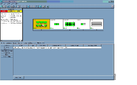
You can view the software versions, embedded network element, and browser that are installed on an ONS 15305 by selecting the Maintenance > Software tabs in node view ( Figure 2). Select the Maintenance tab in network view to view the software versions installed on all the network nodes.

Figure 2 CTC Software Versions in an ONS 15305 (Node View)

CTC Software Installed on the PC or UNIX Workstation

CTC software Java Archive (JAR) files are downloaded from the XTC card and installed on your computer automatically the first time you connect to an ONS 15305. Downloading the CTC software files at login ensures that your computer has the same CTC software version as the ONS 15305 you are accessing. The CTC JAR files are stored in the temporary directory designated by your computer operating system.

You can use the Delete CTC Cache button to remove files. If the JAR files are deleted, they are downloaded the next time you connect to an ONS node. Downloading the CTC JAR files may take 1-2 minutes, or 45-50 minutes, depending on the bandwidth of the connection between your PC/workstation and the ONS 15305. JAR files downloaded from a modem or a data communication channel (DCC) network link will require more time than JAR files downloaded over a LAN connection.


Note Upgrading the CTC software will overwrite your existing software. You must restart CTC after the upgrade is complete.


CTC Installation Overview

To connect to an ONS 15305 using CTC, enter the ONS 15305 IP address in the URL field of Navigator or Microsoft Internet Explorer. After connecting to an ONS 15305, the following events occur automatically:

1. The CTC launcher applet downloads from the ONS 15305 card to your computer.

2. The launcher starts CTC. The CTC session is separate from the web browser session, so the web browser is no longer needed.

3. If the JAR files are installed on your computer, you can log into ONS 15454s running Release 4.6.x or later to manage ONS 15305 nodes that are connected by DCCs to the ONS 15454s.

Each ONS 15305 can handle up to five concurrent CTC sessions. CTC performance can vary, depending on the volume of activity in each session, network bandwidth, and XTC card load.

PC and UNIX Workstation Requirements

To use CTC, your computer must have a web browser with the correct Java Runtime Environment (JRE) installed for the software release in use. You can obtain the correct JRE from Sun Microsystems. Table 1 lists the requirements for PCs and UNIX workstations.

Table 1 CTC Computer Requirements 

Area
Requirements
Notes

Processor (PC only)

Pentium 4 processor or equivalent

A faster CPU is recommended if your workstation runs multiple applications or if CTC manages a network with a large number of nodes and circuits.

RAM

512 MB or more

A minimum of 1 GB is recommended if your workstation runs multiple applications or if CTC manages a network with a large number of nodes and circuits.

Hard drive

20 GB hard drive with 80 MB of space available

CTC application files are downloaded from the XTC card to your computer's Temp directory. These files occupyup to 80 MB of hard drive space.

Operating system

PC: Windows 98, Windows NT 4.0, Windows 2000, or Windows XP

Java Runtime Environment

JRE 1.4.2

JRE 1.4.2 provides enhancements to CTC performance, especially for large networks with numerous circuits.

Web browser

PC: Internet Explorer 6.x, Netscape 7.x

For the PC, use JRE 1.4.2 with any supported web browser. Cisco recommends Internet Explorer 6.x.

Netscape 4.76 or 7.x is available at the following site: http://channels.netscape.com/ns/browsers/default.jsp

Internet Explorer 6.x is available at the following site: http://www.microsoft.com

Cable

User-supplied CAT-5 crossover cable with RJ-45 connectors on each end to connect the computer to the ONS 15305 directly or through a LAN


ONS 15305 Connection

Table 2 lists the connection options and requirements for connecting a PC to the ONS 15305 node.

Table 2 ONS 15305 Connection Methods 

Method
Description
Requirements

Local craft

Refers to onsite network connections between the CTC computer and the ONS 15305 on the XTC card.

If you do not use Dynamic Host Configuration Protocol (DHCP), you must change the computer IP address, subnet mask, and default router, or use automatic host detection.

Corporate LAN

Refers to a connection to the ONS 15305 through a corporate or network operations center (NOC) LAN.

The ONS 15305 must be provisioned for LAN connectivity, including IP address, subnet mask, default gateway.

The ONS 15305 must be physically connected to the corporate LAN.

The CTC computer must be connected to the corporate LAN that has connectivity to the ONS 15305.

Remote

Refers to a connection made to the ONS 15305 using a modem.

A modem must be connected to the ONS 15305.

The modem must be provisioned for the ONS 15305. To run CTC, the modem must be provisioned for Ethernet access.


Note You cannot have more than two management systems connected to a network having ONS 15305 node. You can consider CTM and CTC as two management systems.


Note If ONS 15454 and ONS 15305 nodes are on the same subnet and connected to each other by DCC:

Do not connect the ONS 15305 node on the LAN (arpproxy caveat)

Do not enable SOCKS proxy on the ONS 15454 node

Configure a static default route in the LAN connected ONS 15454 node (0.0.0.0) to enable the ONS 15305 node to access the external DCN.


Features Not Available Through CTC for the ONS 15305

The following features are not available in CTC for the ONS 15305. You must use the Cisco Edge Craft Release 2.2.0 software to access these features/processes.

IP numbered system mode (IP unnumbered system mode is available through CTC)

Alarm profile modification

Path trace

Intermediate Path Performance Monitoring (IPPM)

Ethernet statistics

Ethernet Remote Monitoring (RMON) thresholds

Conditions

Conditions history

Bridge unicast forwarding

Bridge port statistics

Link aggregation

TCP/IP

"TL-1 like" circuits (CTC can only create end-end circuits)

All other features that are typically part of CTC Software Release 5.0 for other ONS products are available for the ONS 15305.

CTC Window

The CTC window appears after you log into an ONS 15305. The CTC window includes a menu bar, toolbar, and a top and bottom pane. The top pane provides status information about the selected objects and a graphic of the current view. The bottom pane provides tabs and subtabs to view ONS 15305 information and perform provisioning and maintenance. The CTC window provides three views: network, node, and card.

Node View

Node view is the first view that appears after you log into an ONS 15305. The login node is the first node shown, and it is the "home view" for the session. Node view allows you to view and manage one node. The status area shows the node name; IP address; session boot date and time; number of Critical (CR), Major (MJ), and Minor (MN) alarms; the name of the current logged-in user; the security level of the user; the software version; and the network element default setup.

CTC Card Colors

The graphic area of the CTC window depicts the shelf assembly. The colors of the cards in the graphic reflect the real-time status of the physical card and slot ( Table 3).

Table 3 Node View Card and Slot Colors 

Card and Slot Color
Status

Gray

Slot is not provisioned; no card is installed.

Violet

Slot is provisioned; no card is installed.

White

Slot is provisioned; a functioning card is installed.

Yellow

Slot is provisioned; a Minor alarm condition exists.

Orange

Slot is provisioned; a Major alarm condition exists.

Red

Slot is provisioned; a Critical alarm exists.


The port color in both card and node view indicates the port service state. Table 4 lists the port colors and their service states.

Table 4 Node View Card Port Colors and Service States 

Port Color
Service State
Description

Gray

OOS

(Out-of-Service) The port is out-of-service and unable to carry traffic.

Green

IS

(In-Service) The port is fully operational and performing as provisioned. The port transmits a signal and displays alarms.

Violet

OOS-AU,AINS

(Out-of-Service and Autonomous, Automatic In-Service) The port is out-of-service, but traffic is carried. Alarm reporting is suppressed. The node monitors the ports for an error-free signal. After an error-free signal is detected, the port stays in OOS-AU,AINS state for the duration of the soak period. After the soak period ends, the port service state changes to IS-NR.

Raised fault conditions, whether or not their alarms are reported, can be retrieved on the CTC Conditions tab. The AINS port will automatically transition to IS-NR when a signal is received for the length of time provisioned in the soak field.


Figure 3 Terminal Loopback Indicator

Figure 4 Facility Loopback Indicator

Table 5 lists the card statuses.

Table 5 Node View Card Statuses

Card Status
Description

Stby

Card is in standby.

Act

Card is active.

NP

Card is not present.

Mis

Card is mismatched.

Ldg

Card is resetting.


Node View Card Shortcuts

If you move your mouse over cards in the graphic, popups display additional information about the card including the card type; card status (active or standby); the type of alarm, such as Critical, Major, and Minor (if any); and the alarm profile used by the card. Right-click a card to reveal a shortcut menu, which you can use to open, reset, or delete the card. Right-click a card slot to preprovision it before installing the card.

Node View Tabs

Table 6 lists the tabs and subtabs available in the node view.

Table 6 Node View Tabs and Subtabs 

Tab
Description
Subtabs

Alarms

Lists current alarms (CR, MJ, MN) for the node and updates them in real time.

Conditions

Displays a list of standing conditions on the node.

History

Provides a history of node alarms including date, type, and severity of each alarm. The Session subtab displays alarms and events for the current session. The Node subtab displays alarms and events retrieved from a fixed-size log on the node.

Session, Node

Circuits

Creates, deletes, and edits circuits.

Circuits

Provisioning

Provisions the ONS 15305 node.

General, EtherBridge, Network, Protection, Security, SNMP, DCC/Inband, Timing, Alarm Profiles, Thresholds

Inventory

Provides inventory information (equipment type, part number, serial number) for cards installed in the node. Allows you to delete, reset, and shut down cards.

Maintenance

Performs maintenance tasks for the node.

Database, Protection, Software, Overhead XConnect, Thresholds, Timing, Routing Table


Network View

Network view allows you to view and manage ONS 15305 nodes that have DCC connections to the node that you logged into and any login node groups you have selected. Nodes with DCC connections to the login node will not appear if you selected Disable Network Discovery on the Login dialog box.

The graphic area displays a background image with colored ONS 15305 icons. A Superuser can set up the logical network view feature, which enables each user to see the same network view. Selecting a node or span in the graphic area displays information about the node and span in the status area. The icon colors indicate the node status.

CTC Node Colors

The color of a node in network view indicates the node alarm status. Table 7 lists the node colors shown in network view.

Table 7 Node Colors Indicating Status in Network View  

Color
Alarm Status

Green

No alarms

Yellow

Minor alarms

Orange

Major alarms

Red

Critical alarms

Gray with Unknown#

Node initializing for the first time (CTC displays Unknown# because CTC has not yet discovered the name of the node)


Network View Tabs

Table 8 lists the tabs and subtabs available in the network view.

Table 8 Network View Tabs and Subtabs 

Tab
Description
Subtabs

Alarms

Lists current alarms (CR, MJ, MN) for the network and updates them in real time.

Conditions

Displays a list of standing conditions on the network.

History

Provides a history of network alarms including date, type, and severity of each alarm.

Circuits

Creates, deletes, edits, filters, and searches for network circuits.

Provisioning

Provision security, alarm profiles, BLSRs, and overhead circuits.

Security, Alarm Profiles, MS-SPring, Overhead Circuits, Provisionable Patchcords (PPC), Server Trails

Maintenance

Displays the type of equipment and the status of each node in the network; displays working and protect software versions, and allows software to be downloaded.

Software, Diagnostic


DCC Links

The lines between nodes in the network view indicate DCC connections between the nodes. Active DCC connections appear as green/solid or green/dashed. Solid means circuits can be routed through the link, and dashed means circuits cannot be routed through the link. A gray link is in a fail state.

Card View

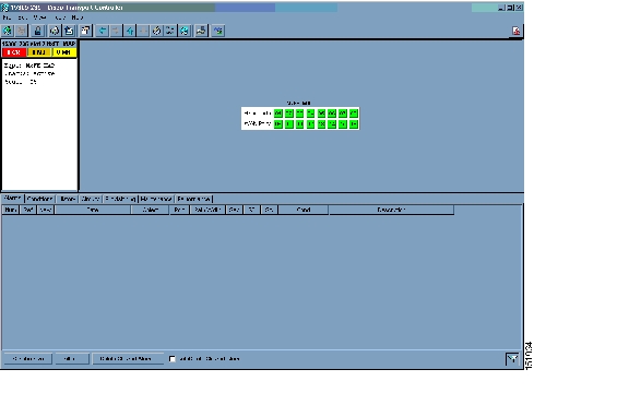
Card view provides information about individual ONS 15305 cards. Use this view to perform card-specific maintenance and provisioning ( Figure 5). A graphic showing the ports on the card appears in the graphic area. The status area provides the node name, slot, number of alarms, card type, equipment type, and either the card status (active or standby), card service state if the card is present, or port service state ( Table 4). The information that appears and the actions you can perform depend on the card.

Figure 5 CTC Card View in an ONS 15305 Showing an NxFE_MAP Card

Table 9 shows the tabs and subtabs available in card view. The subtabs, fields, and information shown under each tab depend on the card type selected.

Table 9 Card View Tabs and Subtabs 

Tab
Description
Subtabs

Alarms

Lists current alarms (CR, MJ, MN) for the card and updates them in real-time.

Conditions

Displays a list of standing conditions on the card.

History

Provides a history of card alarms including date, object, port, and severity of each alarm.

Session (displays alarms and events for the current session), Card (displays alarms and events retrieved from a fixed-size log on the card).

Circuits

Creates, deletes, edits, and search circuits, and completes rolls.

Provisioning

Provisions a card.

XTC card: External Alarms; Management Port; Auxiliary Port; Power.

NxFE MAP card: Ether Ports; WAN Ports; Ether Card; VLAN (subtabs VLAN and GVRP); Wan VLAN (subtabs VLAN and GVRP); Provider VLAN; Bridge (subtabs MultiCastForwardUnregistered, MultiCastForwardingAll, MultiCastStatic, MultiCastForwarding, Port Priority, RSTP Port).

STM4_2 card: Line.

STM1_8 card: STM Ports, WAN Ports, WAN VLAN, Bridge.

STM1_2_E1_21 E1 card: Line, STM Line.

E100_8 card: Ether Port, Ether Vlan, Ether Card, Ether Thresholds, Bridge.

GE_2 card: Ether Port, Ether Vlan, Ether Card, Ether Thresholds, Bridge.

NxGE MAP card: Ether Ports; Ether Card; VLAN (subtabs VLAN and GVRP); Provider VLAN; Bridge (subtabs MultiCastForwardUnregistered, MultiCastForwardingAll, MultiCastStatic, MultiCastForwarding, Port Priority, RSTP Port).

NxGE_MAP p1 card in Layer 1: Ether Ports, Ether Card, VLAN, Provider VLAN, Bridge.

NxGE_MAP p1 card in Layer 2: Ether Ports, Wan Ports, Ether Card, VLAN, Wan VLAN, Provider VLAN, Bridge (when Port 1 is in Layer 2, a WAN port is available).

Maintenance

Performs maintenance tasks for the card (E1_63 card only).

Loopback, Protection.

Performance

Performs performance monitoring tasks for the card. (Not available for the XTC, NxFE MAP, and NxGE cards.)


Print and Export CTC Data

You can use the File > Print or File > Export options to print or export CTC provisioning information for record keeping or troubleshooting. The functions can be performed in card, node, or network views. The File > Print function sends the data to a local or network printer. File > Export exports the data to a file where it can be imported into other computer applications, such as spreadsheets and database management programs.

Whether you choose to print or export data, you can choose from the following options:

Entire Frame—Prints or exports the entire CTC window including the graphical view of the card, node, or network. This option is available for all windows.

Tabbed View—Prints or exports the lower half of the CTC window containing tabs and data. The printout includes the selected tab (on top) and the data shown in the tab window. For example, if you print the History window tabbed view, you print only history items appearing in the window. This option is available for all windows.

Table Contents—Prints CTC data in table format without graphical representations of shelves, cards, or tabs. This option does not apply to all windows; refer to the print task in the
"Connecting the PC and Logging into the GUI" section for specifics.

The Table Contents option prints all the data contained in a table with the same column headings. For example, if you print the History window Table Contents view, you print all data included in the table whether or not items appear in the window.

Common Control Card Reset

You can XTC card for the ONS 15305 by using the hard-reset or soft-reset commands in CTC. A soft reset reboots the XTC card and reloads the operating system and the application software. A hard reset temporarily removes power from the XTC card and clears all buffer memory. Before you hard-reset a card, put the card in standby mode by completing a soft-reset.

A card must be in the OOS service state before you can perform a hard reset.

Traffic Card Reset

You can reset the traffic cards (NxFE MAP, NxGE, STM4_2, and E1_63, etc.) cards by using the reset command in CTC. A soft reset reboots the card and reloads the operating system and the application software. A hard reset temporarily removes power from the card and clears all buffer memory.

From the node view, select a card and right-click to open a menu with the hard-reset and soft-reset commands. A card must be in the OOS service state before you can perform a hard reset.

Database Backup

You can store a back-up version of the database on the workstation running CTC. This operation should be part of a regular ONS 15305 maintenance program performed at approximately weekly intervals and should also be completed when preparing an ONS 15305 for a pending natural disaster, such as a flood.


Note The following parameters are not backed up and restored: node name, IP address, mask and gateway, and Internet Inter-ORB Protocol (IIOP) port. If you change the node name and then restore a backed up database with a different node name, the circuits will map to the new node name. Cisco recommends keeping a record of the old and new node names.


Software Revert

When you click the Activate button after a software upgrade, the XTC copies the current working database and saves it in a reserved location in the XTC flash memory. If you later need to revert to the original working software load from the protect software load, the saved database installs automatically. You do not need to restore the database manually or recreate circuits.

The revert feature is useful if a maintenance window closes while you are upgrading CTC software. You can revert to the standby software load without losing traffic. When the next maintenance window opens, complete the upgrade and activate the new software load.

Circuits that were created and provisioning that was performed after a software load is activated (upgraded to a higher release) do not reinstate with a revert. The database configuration at the time of activation is reinstated after a revert. This does not apply to maintenance reverts (for example 5.0.1 to 5.0.0), because maintenance releases use the same database.

Connecting the PC and Logging into the GUI

This section explains how to connect Windows PCs to the Cisco ONS 15305 and how to log into Cisco Transport Controller (CTC) software, which is the ONS 15305 Operation, Administration, Maintenance and Provisioning (OAM&P) user interface.

Before You Begin

This section lists the CTC procedures and tasks

1. Set Up Computer for CTC—Complete this procedure if your Windows PC has never been connected to an ONS 15305.

2. Set Up CTC Computer for Local Craft Connection to the ONS 15305—Complete this procedure to set up your computer for an onsite craft connection to the ONS 15305.

3. Set Up a CTC Computer for a Corporate LAN Connection to the ONS 15305—Complete this procedure to set up your computer to connect to the ONS 15305 using a corporate LAN.

4. Log into the ONS 15305 GUI—Complete this procedure to log into CTC.

Set Up Computer for CTC

Purpose

This procedure configures your Windows PC to run CTC.

Tools/Equipment

Cisco ONS 15305 Release 3.0 software CD

Prerequisite Procedures

Install all cards and cables

Required/As Needed

Required

Onsite/Remote

Onsite or remote

Security Level

None


Note JRE 1.4.2 is required to log into nodes running Software Release 3.0. You can obtain the JRE from the Sun Microsystems web site at http://java.sun.com/j2se/1.4.2/download.html. Complete the "Change the JRE Version" task as needed.


Step 1 If your computer does not have an appropriate browser installed, complete the following:

To install Netscape 4.76 or 7.x on a Windows PC, download the browser from the following site: http://channels.netscape.com/ns/browsers/default.jsp

To install Internet Explorer 6.x on a Windows PC, download the browser from the following site: http://www.microsoft.com\

Step 2 Download CTC by following the instructions found in the CECreadme.txt file on the Cisco ONS 15305, Release 3.0 software CD. (You will use the Cisco Edge Craft (CEC) software to download CTC.)

Stop. You have completed this procedure.


Change the JRE Version

Purpose

This task changes the JRE version, which is useful if you would like to upgrade to a later JRE version from an earlier one without using the software or documentation CD. This does not affect the browser default version. After selecting the desired JRE version, you must exit CTC. The next time you log into a node, the new JRE version will be used.

Tools

None

Prerequisite Procedures

Log into CTC

Required/As Needed

As needed

Onsite/Remote

Onsite or remote

Security Level

Provisioning or higher


Note JRE version 1.4.2 is required to operate the ONS 15305 CTC.


Step 1 From the Edit menu, choose Preferences.

Step 2 Click the JRE tab. The JRE tab shows the current JRE version and the recommended and supported versions.

Step 3 Click the Browse button and navigate to the JRE directory on your computer.

Step 4 Choose the JRE version.

Step 5 Click Open, then click OK.

Step 6 From the File menu, choose Exit.

Step 7 In the confirmation dialog box, click Yes.

Step 8 Log out of the ONS node.

Step 9 In the web browser that you used to log into the node, click Delete CTC Cache.

Step 10 Click Yes on the confirmation dialog box, then close the browser window.

Step 11 Complete the "Log into CTC" task.

Step 12 Return to your originating procedure (NTP).


Set Up CTC Computer for Local Craft Connection to the ONS 15305

Purpose

This procedure explains how to set up a PC running Windows for an onsite local craft connection to the ONS 15305.

Tools/Equipment

Network interface card (NIC), also referred to as an Ethernet card

Crossover (CAT-5) LAN cable

Serial cable (provided in the ship kit)

Prerequisite Procedures

Set Up Computer for CTC

Required/As Needed

As needed

Onsite/Remote

Onsite or remote

Security Level

None


Step 1 Complete one of the CTC computer setup tasks shown in Table 4-10 based on your CTC connection environment. For initial setup, use Option 1 or 3.

Table 4-10 CTC Computer Setup for Local Craft Connections to the ONS 15305 

Option
CTC Connection Environment
CTC Computer Setup Task 

1

You are connecting from a Windows PC.

You will connect to one ONS 15305.

You need to access non-ONS 15305 applications such as ping and tracert (trace route).

Set Up a Windows PC for Craft Connection to an ONS 15305 on the Same Subnet Using Static IP Addresses

2

You are connecting from a Windows PC.

Your network uses Dynamic Host Configuration Protocol (DHCP) for assignment of host IP addresses.

The CTC computer is provisioned for DHCP.

The ONS 15305 has DHCP forwarding enabled.

The ONS 15305 is connected to a DHCP server.

Note The ONS 15305 does not provide IP addresses. If DHCP is enabled, it passes DCHP requests to an external DHCP server.

Set Up a Windows PC for Craft Connection to an ONS 15305 Using Dynamic Host Configuration Protocol

Note Do not use this task for initial node turn-up. Use the task only if DHCP forwarding is enabled on the ONS 15305. By default, DHCP is not enabled.

3

You are connecting from a Windows PC.

You will connect to ONS 15305s at different locations and times and do not wish to reconfigure your PC's IP settings each time.

You will not access or use non-ONS 15305 applications such as ping and tracert (trace route).

You will connect to the VT100 port either directly or through a hub.

Set Up a Windows PC for Craft Connection to an ONS 15305 Using Automatic Host Detection


Step 2 Connect a crossover CAT-5 LAN cable from the Windows PC NIC to one of the following:

The RJ-45 VT100 port on the XTC card. Use this method for the initial shelf turn-up.

The RJ-45 (LAN) port on a hub or switch to which the ONS 15305 is physically connected.


Note A special serial cable for connecting to the VT100 port on the XTC is provided in the ONS 15305 ship kit.


Step 3 After setting up your CTC computer, continue with the "Log into the ONS 15305 GUI" procedure as needed.

Stop. You have completed this procedure.


Set Up a Windows PC for Craft Connection to an ONS 15305 on the Same Subnet Using Static IP Addresses

Purpose

This task sets up your computer for a local craft connection to the ONS 15305 when:

You will connect to one ONS 15305; if you will connect to multiple ONS 15305s, you might need to reconfigure your computer's IP settings each time you connect to an ONS 15305.

You need to use non-ONS 15305 applications such as ping and tracert (trace route).

Tools/Equipment

None

Prerequisite Procedures

Set Up Computer for CTC

Required/As Needed

As needed

Onsite/Remote

Onsite

Security Level

None


Step 1 Verify the operating system that is installed on your computer:

a. From the Windows Start menu, choose Settings > Control Panel.

b. In the Control Panel window, double-click the System icon.

c. On the General tab of the System Settings window, verify that the Windows operating system is one of the following: Windows 98, Windows NT 4.0, Windows 2000, or Windows XP.

Step 2 According to the Windows operating system installed on your computer, perform one of the following steps:

For Windows 98, complete Step 3.

For Windows NT 4.0, complete Step 4.

For Windows 2000, complete Step 5.

For Windows XP, complete Step 6.

Step 3 If you have Windows 98 installed on your PC, complete the following steps to change its TCP/IP configuration:

a. From the Windows Start menu, choose Settings > Control Panel.

b. In the Control Panel dialog box, click the Network icon.

c. In the Network dialog box, choose TCP/IP for your NIC card, then click Properties.

d. In the TCP/IP Properties dialog box, click the DNS Configuration tab and choose Disable DNS.

e. Click the WINS Configuration tab and choose Disable WINS Resolution.

f. Click the IP Address tab.

g. In the IP Address window, click Specify an IP address.

h. In the IP Address field, enter an IP address that is identical to the ONS 15305 IP address except for the last octet. The last octet must be 1 or 3 through 254.

i. In the Subnet Mask field, type the same subnet mask as the ONS 15305. The default is 255.255.255.0 (24 bit).

j. Click OK.

k. In the TCP/IP dialog box, click the Gateway tab.

l. In the New Gateway field, type the ONS 15305 IP address. Click Add.

m. Verify that the IP address appears in the Installed Gateways field, then click OK.

n. When the prompt to restart your PC appears, click Yes.

o. Proceed to Step 7.

Step 4 If you have Windows NT 4.0 installed on your PC, complete the following steps to change its TCP/IP configuration:

a. From the Windows Start menu, choose Settings > Control Panel.

b. In the Control Panel dialog box, click the Network icon.

c. In the Network dialog box, click the Protocols tab, choose TCP/IP Protocol, then click Properties.

d. Click the IP Address tab.

e. In the IP Address window, click Specify an IP address.

f. In the IP Address field, enter an IP address that is identical to the current ONS 15305 IP address. The last octet must be 1 or 3 through 254.

g. In the Subnet Mask field, type 255.255.255.0.

h. Click Advanced.

i. In the Gateways List, click Add. The TCP/IP Gateway Address dialog box appears.

j. Type the ONS 15305 IP address in the Gateway Address field.

k. Click Add.

l. Click OK.

m. Click Apply.

n. In some cases, Windows NT 4.0 prompts you to reboot your PC. If you receive this prompt, click Yes.

o. Proceed to Step 7.

Step 5 If you have Windows 2000 installed on your PC, complete the following steps to change its TCP/IP configuration:

a. From the Windows Start menu, choose Settings > Network and Dial-up Connections > Local Area Connection.

b. In the Local Area Connection Status dialog box, choose the local area connection connected to the PC port connected to the ONS 15305.

c. Click Properties.

d. On the General tab, choose Internet Protocol (TCP/IP), then click Properties.

e. Click Use the following IP address.

f. In the IP Address field, enter an IP address that is identical to the ONS 15305 IP address except for the last octet. The last octet must be 1 or 3 through 254.

g. In the Subnet Mask field, type 255.255.255.0.

h. In the Default Gateway field, type the ONS 15305 IP address.

i. Click OK.

j. In the Local Area Connection Properties dialog box, click OK.

k. In the Local Area Connection Status dialog box, click Close.

l. Proceed to Step 7.

Step 6 If you have Windows XP installed on your PC, complete the following steps to change its TCP/IP configuration:

a. From the Windows Start menu, choose Control Panel > Network Connections.


Note If the Network Connections menu is not available, right-click the Windows screen and choose Properties from the popup menu. Click the Appearance tab, then under Scheme, choose Classic View.


b. From the Network Connections dialog box, click the Local Area Connection icon.

c. On the General tab of the Local Area Connection Properties dialog box, choose Internet Protocol (TCP/IP), then click Properties.

d. In the IP Address field, enter an IP address that is identical to the ONS 15305 IP address except for the last octet. The last octet must be 1 or 3 through 254.

e. In the Subnet Mask field, type 255.255.255.0.

f. In the Default Gateway field, type the ONS 15305 IP address.

g. Click OK.

h. In the Local Area Connection Properties dialog box, click OK.

i. In the Local Area Connection Status dialog box, click Close.

Step 7 Return to your originating procedure (NTP).


Set Up a Windows PC for Craft Connection to an ONS 15305 Using Dynamic Host Configuration Protocol

Purpose

This task sets up your computer for craft connection to the ONS 15305 using DHCP.

Tools/Equipment

None

Prerequisite Procedures

Set Up Computer for CTC

You must set up CTC for network access before performing this task.

Required/As Needed

As needed

Onsite/Remote

Onsite

Security Level

None


Note Do not use this task for initial node turn-up. Use the task only if DHCP forwarding is enabled on the ONS 15305. By default, DHCP is not enabled.


Note The ONS 15305 does not provide the IP addresses. If DHCP forwarding is enabled, it passes DCHP requests to an external DHCP server.


Step 1 Verify the operating system that is installed on your computer:

a. From the Windows Start menu, choose Settings > Control Panel.

b. In the Control Panel window, double-click the System icon.

c. On the General tab of the System Settings window, verify that the Windows operating system is one of the following: Windows 98, Windows NT 4.0, Windows 2000, or Windows XP.

Step 2 According to the Windows operating system installed on your computer, perform one of the following steps:

For Windows 98, complete Step 3.

For Windows NT 4.0, complete Step 4.

For Windows 2000, complete Step 5.

For Windows XP, complete Step 6.

Step 3 If you have Windows 98 installed on your PC, complete the following steps to change its TCP/IP configuration:

a. From the Windows Start menu, choose Settings > Control Panel.

b. In the Control Panel dialog box, click the Network icon.

c. In the Network dialog box, select TCP/IP for your NIC, then click Properties.

d. In the TCP/IP Properties dialog box, click the DNS Configuration tab and choose Disable DNS.

e. Click the WINS Configuration tab and choose Disable WINS Resolution.

f. Click the IP Address tab.

g. In the IP Address window, click Obtain an IP address automatically.

h. Click OK.

i. When the prompt to restart your PC appears, click Yes.

j. Proceed to Step 7.

Step 4 If you have Windows NT 4.0 installed on your PC, complete the following steps to change its TCP/IP configuration:

a. From the Windows Start menu, choose Settings > Control Panel.

b. In the Control Panel dialog box, click the Network icon.

c. In the Network dialog box, click the Protocols tab, choose TCP/IP Protocol, then click Properties.

d. Click the IP Address tab.

e. In the IP Address window, click Obtain an IP address from a DHCP server.

f. Click OK.

g. Click Apply.

h. If Windows prompts you to restart your PC, click Yes.

i. Proceed to Step 7.

Step 5 If you have Windows 2000 installed on your PC, complete the following steps to change its TCP/IP configuration:

a. From the Windows Start menu, choose Settings > Network and Dial-up Connections > Local Area Connection.

b. In the Local Area Connection Status dialog box, choose the local area connection connected to the PC port connected to the ONS 15305.

c. In the Local Area Connection Status dialog box, click Properties.

d. On the General tab, choose Internet Protocol (TCP/IP), then click Properties.

e. Click Obtain an IP address automatically.

f. Click OK.

g. In the Local Area Connection Properties dialog box, click OK.

h. In the Local Area Connection Status dialog box, click Close.

i. Proceed to Step 7.

Step 6 If you have Windows XP installed on your PC, complete the following steps to change its TCP/IP configuration:

a. From the Windows Start menu, choose Control Panel > Network Connections.


Note If the Network Connections menu is not available, right-click the Windows screen and choose Properties from the popup menu. Click the Appearance tab, then under Scheme, choose Classic View.


b. From the Network Connections dialog box, click the Local Area Connection icon.

c. On the General tab of the Local Area Connection Properties dialog box, click Properties.

d. On the General tab, choose Internet Protocol (TCP/IP), then click Properties.

e. Click Obtain an IP address automatically.

f. Click OK.

g. In the Local Area Connection Properties dialog box, click OK.

h. In the Local Area Connection Status dialog box, click Close.

Step 7 Return to your originating procedure (NTP).


Set Up a Windows PC for Craft Connection to an ONS 15305 Using Automatic Host Detection

Purpose

This task sets up your computer for local craft connection to the ONS 15305 when:

You will connect to the ONS 15305 VT100 port either directly or through a hub.

You will connect to multiple ONS 15305s and do not want to reconfigure your IP address each time.

You do not need to access non-ONS 15305 applications such as ping and tracert (trace route).

Tools/Equipment

None

Prerequisite Procedures

Set Up Computer for CTC

Required/As Needed

As needed

Onsite/Remote

Onsite

Security Level

None


Step 1 Verify the operating system that is installed on your computer:

a. From the Windows Start menu, choose Settings > Control Panel or, for Windows XP, Control Panel > System.

b. In the Control Panel window, double-click the System icon.

c. On the General tab of the System Settings window, verify that the Windows operating system is one of the following: Windows 98, Windows NT 4.0, Windows 2000, or Windows XP.

Step 2 According to the Windows operating system installed on your computer, perform one of the following steps:

For Windows 98, complete Step 3.

For Windows NT 4.0, complete Step 4.

For Windows 2000, complete Step 5.

For Windows XP, complete Step 6.

Step 3 If you have Windows 98 installed on your PC, complete the following steps to change its TCP/IP configuration:

a. From the Windows Start menu, choose Settings > Control Panel.

b. In the Control Panel dialog box, click the Network icon.

c. In the Network dialog box, select TCP/IP for your NIC, then click Properties.

d. In the TCP/IP Properties dialog box, click the DNS Configuration tab and choose Disable DNS.

e. Click the WINS Configuration tab and choose Disable WINS Resolution.

f. Click the IP Address tab.

g. In the IP Address window, click Specify an IP address.

h. In the IP Address field, enter any legitimate IP address other than the current node IP address. The default IP address is 0.0.0.0.

i. In the Subnet Mask field, type the same subnet mask as the ONS 15305. The default is 255.255.255.0 (24 bit).

j. Click OK.

k. In the TCP/IP dialog box, click the Gateway tab.

l. In the New Gateway field, type the address entered in Step h. Click Add.

m. Verify that the IP address appears in the Installed Gateways field, then click OK.

n. When the prompt to restart your PC appears, click Yes.

o. Proceed to Step 7.

Step 4 If you have Windows NT 4.0 installed on your PC, complete the following steps to change its TCP/IP configuration:

a. From the Windows Start menu, choose Settings > Control Panel.

b. In the Control Panel dialog box, click the Network icon.

c. In the Network dialog box, click the Protocols tab, choose TCP/IP Protocol, then click Properties.

d. Click the IP Address tab.

e. In the IP Address window, click Specify an IP address.

f. In the IP Address field, enter any legitimate IP address other than the current node IP address. The default IP address is 0.0.0.0.

g. In the Subnet Mask field, type the same subnet mask as the ONS 15305. The default is 255.255.255.0 (24 bit).

h. Click Advanced.

i. In the Gateways List, click Add. The TCP/IP Gateway Address dialog box appears.

j. Type the IP address entered in Step  f in the Gateway Address field.

k. Click Add.

l. Click OK.

m. Click Apply.

n. Reboot your PC.

o. Proceed to Step 7.

Step 5 If you have Windows 2000 installed on your PC, complete the following steps to change its TCP/IP configuration:

a. From the Windows Start menu, choose Settings > Network and Dial-up Connections > Local Area Connection.

b. In the Local Area Connection Status dialog box, click Properties.

c. On the General tab, choose Internet Protocol (TCP/IP), then click Properties.

d. Click Use the following IP address.

e. In the IP Address field, enter any legitimate IP address other than the current node IP address. The default IP address is 0.0.0.0.

f. In the Subnet Mask field, type the same subnet mask as the ONS 15305. The default is 255.255.255.0 (24 bit).

g. Type the IP address entered in Step  e in the Gateway Address field.

h. Click OK.

i. In the Local Area Connection Properties dialog box, click OK.

j. In the Local Area Connection Status dialog box, click Close.

k. Proceed to Step 7.

Step 6 If you have Windows XP installed on your PC, complete the following steps to change its TCP/IP configuration:

a. From the Windows Start menu, choose Control Panel > Network Connections.


Note If the Network Connections menu is not available, click Switch to Classic View.


b. From the Network Connections dialog box, right-click the Local Area Connection icon and select Properties.

c. Scroll to the bottom of the Local Area Connection Properties dialog box. Click Internet Protocol (TCP/IP) to select it, then click Properties.

d. In the IP Address field, enter any legitimate IP address other than the current IP address. The default IP address is 0.0.0.0.

e. Select the Use the Following IP Address: radio button.

f. In the Subnet Mask field, type the same subnet mask as the ONS 15305. The default is 255.255.255.0 (24 bit).

g. Type the IP address entered in Step  d in the Gateway Address field.

h. Click OK.

i. In the Local Area Connection Properties dialog box, click Close.

Step 7 Return to your originating procedure (NTP).


Set Up a CTC Computer for a Corporate LAN Connection to the ONS 15305

Purpose

This procedure sets up your computer to access the ONS 15305 through a corporate LAN.

Tools/Equipment

NIC, also referred to as an Ethernet card

Crossover(CAT-5) LAN cable

Prerequisite Procedures

Set Up Computer for CTC

The ONS 15305 must be provisioned for LAN connectivity, including IP address, subnet mask, default gateway.

The ONS 15305 must be physically connected to the corporate LAN.

Required/As Needed

As needed

Onsite/Remote

Onsite or remote

Security Level

None


Step 1 If your computer is already connected to the corporate LAN, go to Step 3. If you changed your computer's network settings for craft access to the ONS 15305, change the settings back to the corporate LAN access settings. This generally means:

Set the IP Address on the TCP/IP dialog box back to Obtain an IP address automatically (Windows 2000 and XP) or Obtain an IP address from a DHCP server (Windows NT 4.0).

If your LAN requires that Domain Name System (DNS) or Windows Internet Naming Service (WINS) be enabled, change the setting on the DNS Configuration or WINS Configuration tab of the TCP/IP dialog box.

Step 2 Connect a crossover (CAT-5) LAN cable from the PC NIC card to a corporate LAN port.

Step 3 If your computer is connected to a proxy server, disable proxy service or add the ONS 15305 nodes as exceptions. To disable or bypass proxy service, complete one of the following tasks, depending on the web browser that you use:

Disable or Bypass Proxy Service Using Internet Explorer (Windows)

Disable or Bypass Proxy Service Using Netscape (Windows)

Step 4 Continue with the "Log into the ONS 15305 GUI" procedure.

Stop. You have completed this procedure.


Disable or Bypass Proxy Service Using Internet Explorer (Windows)

Purpose

This task disables or bypasses proxy service for PCs running Internet Explorer.

Tools/Equipment

None

Prerequisite Procedures

Set Up Computer for CTC

Required/As Needed

Required if your computer is connected to a network computer proxy server and your browser is Internet Explorer.

Onsite/Remote

Onsite or remote

Security Level

None


Step 1 From the Start menu, select Settings > Control Panel.


Note If your computer is running Windows XP, you can select Control Panel directly from the Start menu. Make sure that you are in Classic View before continuing with this procedure. To switch to Classic View, right-click the Windows screen and choose Properties from the popup menu. Click the Appearance tab, then under Scheme, choose Classic View.


Step 2 In the Control Panel window, choose Internet Options.

Step 3 In the Internet Properties dialog box, click Connections > LAN Settings.

Step 4 In the LAN Settings dialog box, complete one of the following tasks:

Uncheck Use a proxy server to disable the service.

To bypass the service, leave Use a proxy server selected and click Advanced. In the Proxy Setting dialog box under Exceptions, enter the IP addresses of ONS 15305 nodes that you will access. Separate each address with a semicolon. You can insert an asterisk (*) for the host number to include all the ONS 15305s on your network. Click OK to close each open dialog box.

Step 5 Return to your originating procedure (NTP).


Disable or Bypass Proxy Service Using Netscape (Windows)

Purpose

This task disables or bypasses proxy service for Windows PCs running Netscape.

Tools/Equipment

None

Prerequisite Procedures

Set Up Computer for CTC

Required/As Needed

Required if your computer is connected to a network computer proxy server and your browser is Netscape.

Onsite/Remote

Onsite or remote

Security Level

None


Step 1 Open Netscape (Windows).

Step 2 From the Edit menu, choose Preferences.

Step 3 In the Preferences dialog box under Category, choose Advanced > Proxies.

Step 4 On the right side of the Preferences dialog box under Proxies, perform one of the following options:

Click the Direct connection to the Internet option to disable the proxy server.

Click the Manual proxy configuration option to add exceptions to the proxy server. Under Manual Proxy Configuration in the No Proxy For field, enter the IP addresses of the ONS 15305 nodes that you will access. Separate each address with a comma. Click OK to close each open dialog box.

Step 5 Return to your originating procedure (NTP).


Log into the ONS 15305 GUI

Purpose

This procedure logs into CTC, the graphical user interface (GUI) software used to manage the ONS 15305. This procedure includes optional node login tasks.

Tools/Equipment

None

Prerequisite Procedures

Set Up Computer for CTC

One of the following procedures:

Set Up CTC Computer for Local Craft Connection to the ONS 15305

Set Up a CTC Computer for a Corporate LAN Connection to the ONS 15305

Required/As Needed

Required

Onsite/Remote

Onsite or remote

Security Level

Retrieve or higher


Step 1 Complete the "Log into CTC" task.


Note For information about navigating in CTC, see "CTC Information and Shortcuts" section.


During network topology discovery, CTC polls each node in the network to determine which one contains the most recent version of the CTC software. If CTC discovers a node in the network that has a more recent version of the CTC software than the version you are currently running, CTC generates a message stating that a later version of the CTC has been found in the network. If you have network discovery disabled, CTC will not seek more recent versions of the software. Unreachable nodes are not included in the upgrade discovery.


Note Upgrading the CTC software will overwrite your existing software. You must restart CTC after the upgrade is complete.


Step 2 As needed, complete the "Create Login Node Groups" task. Login node groups allow you to view and manage nodes that have an IP connection but no data communications channel (DCC) connection to the login node.

Step 3 As needed, complete the "Add a Node to the Current Session or Login Group" task.

Step 4 As needed, complete the "Delete a Node from the Current Session or Login Group" task.

Step 5 As needed, complete the "Adjust the Java Virtual Memory Heap Size (Windows)" task.

Step 6 As needed, complete the "Delete a Node from a Specific Login Node Group" task.

Step 7 As needed, complete the "Configure the CTC Alerts Dialog Box for Automatic Popup" task.

Stop. You have completed this procedure.


Adjust the Java Virtual Memory Heap Size (Windows)

Purpose

This task allows you to adjust the Java Virtual Memory (JVM) heap size of a Windows PC from the default 256 MB to the maximum of 512 MB in order to improve CTC performance.

Tools/Equipment

None

Prerequisite procedures

None

Required/As needed

As needed

Onsite/Remote

Onsite or remote

Security Level

Provisioning or higher


Note The task adjusts the physical memory allocation in the computer RAM so that more space is allocated for CTC. However, less physical memory will be available for other computer processes and programs. If you notice performance degradation of non-CTC programs after completing this task, reduce the JVM allotted to CTC. You may need to repeat the task a few times to find the right balance between JVM allotted to CTC and to other programs on your computer.


Step 1 From the Windows PC, click Start > Settings > Control Panel. > System, or Start > Control Panel > System (Windows XP). The Windows Control Panel appears. The System Properties dialog box appears.

Step 2 Click the Advanced tab.

Step 3 Click Environmental Variables. The Environmental Variables dialog box appears.

Step 4 In the User Variables area, check to see whether a CTC_HEAP variable was created. If yes, complete the following steps. If not, continue with Step 5.

a. Check the CTC_HEAP value. If it is 512, continue with Step 12. If not, continue with Step b.

b. Click the CTC_HEAP variable and click Edit.

c. In the Edit User Variable dialog box, enter the new JVM heap size. This can be any number between 256 and 512 MB.

d. Click OK, then continue with Step 9.

Step 5 click New. The New User Variable dialog box appears.

Step 6 Type "CTC_HEAP" in the Variable Name field.

Step 7 Type "512" in the Variable Value field.

Step 8 Click OK to close the New User Variable dialog box.

Step 9 Click OK to close the Environmental Variables dialog box.

Step 10 Click OK to close the System Properties dialog box.

Step 11 Reboot your PC.

Step 12 Return to your originating procedure (NTP).


Log into CTC

Purpose

This task logs into the graphical user interface (GUI) of CTC.

Tools/Equipment

None

Prerequisite Procedures

Set Up Computer for CTC

One of the following procedures:

Set Up CTC Computer for Local Craft Connection to the ONS 15305

Set Up a CTC Computer for a Corporate LAN Connection to the ONS 15305

Required/As Needed

Required

Onsite/Remote

Onsite or remote

Security Level

Retrieve or higher


Note To log into CTC, you must first provision a username and password using the command line interface (CLI).


Note For information about CTC views and navigation, see the "CTC Information and Shortcuts" section.


Step 1 From the computer connected to the ONS 15305, start Netscape (Windows PC) or Internet Explorer (Windows PC) :

Step 2 In the Netscape or Internet Explorer web address (URL) field, enter the ONS 15305 IP address. For initial setup, this is the default IP address, 0.0.0.0.

Step 3 Press Enter. The browser displays a window with a Delete CTC Cache field and information about the Cisco Transport Controller Java and System environments.


Note The Delete CTC Cache field deletes the CTC JAR (Java Archive) files that are downloaded to your computer when you log into an ONS 15305. You perform this action if connectivity problems occur or you want to delete older CTC JAR file versions from your computer.


Note If you are logging into ONS 15305 nodes in an operation network that are running different releases of CTC software, log into the node running the most recent release. If you log into a node running an older release, you will receive an INCOMPATIBLE-SW alarm for each node in the network running a new release, and CTC will not be able to manage these nodes. To check the software version of a node, select About CTC from the CTC Help menu. This will display the ONS 15305 software version for each node visible on the network view.


Step 4 If a Java Plug-in Security Warning dialog box appears, complete the "Install Public-Key Security Certificate" task to install the public-key security certificate required by Software Release 4.1 and later.

After you complete the security certificate dialog box (or if the certificate is already installed), a Java Console window displays the CTC file download status. The web browser displays information about your Java and system environments. If this is the first login, CTC caching messages appear while CTC files are downloaded to your computer. The first time you connect to an ONS 15305, this process can take several minutes. After the download, the CTC Login dialog box appears.


Note When the CTC Login dialog box appears, it might be minimized.


Step 5 In the Login dialog box, type a user name and password (both are case sensitive). For initial setup, type the user name and password you provisioned using the CLI.

Step 6 Each time you log into an ONS 15305, you can make selections about the following login options:

Node Name—Displays the IP address entered in the web browser and a drop-down list of previously entered ONS 15305 IP addresses. You can select any ONS 15305 on the list for the login, or you can enter the IP address (or node name) of any new node where you want to log in.

Additional Nodes—Displays a list of current login node groups. To create a login node group or add additional groups, see the "Create Login Node Groups" task.

Disable Network Discovery—Check this box to view only the ONS 15305 (and additional nodes within the login node group, if any) entered in the Node Name field. Nodes linked to this node through DCCs are not discovered and will not appear in CTC network view. Using this option can decrease the CTC startup time in networks with many DCC-connected nodes, and can reduce memory consumption.

Disable Circuit Management—Check this box to disable discovery of existing circuits. Using this option can decrease the CTC initialization time in networks with many existing circuits and reduce memory consumption. After you are logged in, you can enable circuit discovery at any time by choosing the Enable Circuit Discovery button on the Circuits tab.

Step 7 If you keep Disable Network Discovery unchecked, CTC attempts to upgrade the CTC software by downloading more recent versions of the JAR files it finds during the network discovery. Click Yes to allow CTC to download the newer JAR files, or No to prevent CTC from downloading the JAR files.


Note Upgrading the CTC software will overwrite your existing software. You must restart CTC after the upgrade is complete.


Step 8 Click Login.

If the login is successful, the CTC node view window appears. From here, you can navigate to other CTC views to provision and manage the ONS 15305.

Step 9 Return to your originating procedure (NTP).


Install Public-Key Security Certificate

Purpose

This task installs the ITU Recommendation X.509 public-key security certificate. The public-key certificate is required to run Software Release 4.6.

Tools/Equipment

None

Prerequisite Procedures

This task is performed during the "Log into CTC" task. You cannot perform it outside of this task.

Required/As Needed

Required

Onsite/Remote

Onsite or remote

Security Level

Provisioning or higher


Step 1 If the Java Plug-in Security Warning dialog box appears, choose one of the following options:

Yes (Grant This Session)—Installs the public-key certificate to your PC only for the current session. After the session is ended, the certificate is deleted. This dialog box will appear the next time you log into the ONS 15305.

No (Deny)—Denies permission to install the certificate. If you choose this option, you cannot log into the ONS 15305.

Always (Grant Always)—Installs the public-key certificate and does not delete it after the session is over. Cisco recommends this option.

More Details (View Certificate)—Allows you to view the public-key security certificate.

Step 2 Return to your originating procedure (NTP) or task (DLP).


Create Login Node Groups

Purpose

This task creates a login node group to display ONS 15305s that have an IP connection but not a data channel connection (DCC) to the login node.

Tools/Equipment

None

Prerequisite Procedures

Log into CTC

Required/As Needed

As needed

Onsite/Remote

Onsite or remote

Security Level

Provisioning or higher


Step 1 From the Edit menu in node view, choose Preferences.

Step 2 Click Login Node Group and Create Group.

Step 3 Enter a name for the group in the Create Login Group Name dialog box. Click OK.

Step 4 In the Members area, type the IP address (or node name) of a node you want to add to the group. Click Add. Repeat this step for each node that you want to add to the group.

Step 5 Click OK.

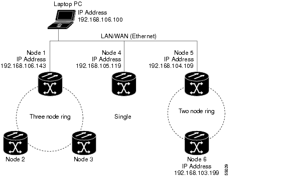
The next time you log into an ONS 15305, the login node group will be available in the Additional Nodes list of the Login dialog box. For example, in Figure 4-6, a login node group is created that contains the IP addresses for Nodes 1, 4, and 5. During login, if you choose this group from the Additional Nodes list and Disable Network Discovery is not selected, all nodes in the figure appear. If the login group and Disable Network Discovery are both selected, only Nodes 1, 4, and 5 appear. You can create as many login node groups as you need. The groups are stored in the CTC preferences file and are not visible to other users.

Figure 4-6 Login Node Group

Step 6 Return to your originating procedure (NTP).


Add a Node to the Current Session or Login Group

Purpose

This task adds a node to the current CTC session or login node group.

Tools

None

Prerequisite Procedures

Log into CTC

Required/As Needed

As needed

Onsite/Remote

Onsite or remote

Security Level

Provisioning or higher


Step 1 In any CTC view, from the CTC File menu, click Add Node.

Step 2 In the Add Node dialog box, enter the node name (or IP address).

Step 3 If you want to add the node to the current login node group, check Add to current login node group. Otherwise, leave it unchecked.


Note This check box is active only if you selected a login group when you logged into CTC.


Step 4 Click OK.

After a few seconds, the new node appears on the network view map.

Step 5 Return to your originating procedure (NTP).


Delete a Node from the Current Session or Login Group

Purpose

This task removes a node from the current CTC session or login node group. To remove a node from a login node group that is not the current one, see "Delete a Node from a Specific Login Node Group" task.

Tools

None

Prerequisite Procedures

Log into CTC

Required/As Needed

As needed

Onsite/Remote

Onsite or remote

Security Level

Provisioning or higher


Step 1 From the CTC View menu, choose Go to Network View.

Step 2 On the network map, single-click the node that you want to delete.

Step 3 From the CTC File menu, click Delete Selected Node.

After a few seconds, the node disappears from the network view map.

Step 4 Return to your originating procedure (NTP).


Delete a Node from a Specific Login Node Group

Purpose

This task removes a node from a specific login node group. To remove a node from the current login node group, see the "Delete a Node from the Current Session or Login Group" task.

Tools

None

Prerequisite Procedures

Log into CTC

Required/As Needed

As needed

Onsite/Remote

Onsite or remote

Security Level

Provisioning or higher


Step 1 In any CTC view, from the CTC Edit menu, choose Preferences.

Step 2 In the Preferences dialog box, click the Login Node Groups tab.

Step 3 Click the login node group tab containing the node you want to remove.

Step 4 Click the node you want to remove, then click Remove.

Step 5 Click OK.

Step 6 Return to your originating procedure (NTP).


Configure the CTC Alerts Dialog Box for Automatic Popup

Purpose

This task sets up the CTC Alerts dialog box to open for all alerts, for circuit deletion errors only, or never. The CTC Alerts dialog box displays network disconnection, Send-PDIP inconsistency, circuit deletion status, condition retrieval errors, and software download failure.

Tools

None

Prerequisite Procedures

Log into CTC

Required/As Needed

As needed

Onsite/Remote

Onsite or remote

Security Level

Provisioning or higher


Step 1 Click the CTC Alerts toolbar icon. (The icon is located on the far right of the CTC toolbar.)

Step 2 In the CTC Alerts dialog box, choose one of the following:

All alerts—Sets the CTC Alerts dialog box to open automatically for all notifications.

Error alerts only—Sets the CTC Alerts dialog box to open automatically for circuit deletion errors only.

Never—Sets the CTC Alerts dialog box to never open automatically.

Step 3 Click Close.

Step 4 Return to your originating procedure (NTP).


CTC Information and Shortcuts

This section describes the Cisco Transport Controller (CTC) views, menus and tool options, shortcuts, and table display options. This appendix also describes the shelf inventory data presented in CTC.

Display Node, Card, and Network Views

CTC provides three views of the ONS 15305 and ONS network:

Node view appears when you first log into an ONS 15305. This view shows a graphic of the ONS 15305 shelf and provides access to tabs and subtabs that you use to manage the node.

Card view provides access to individual ONS 15305 cards. This view provides a graphic of the card and provides access to tabs and subtabs that you use to manage the card.

Network view shows all the nodes in a network. A Superuser can set up this feature so each user will see the same network view, or the user can create a custom view with maps. This view provides access to tabs and subtabs that you use to manage the network.

Table 0-11 lists different actions for changing CTC views.

Table 0-11 Change CTC Views 

To display:
Perform one of the following:

Node view

Log into a node; node view is the default view.

In network view, double-click a node icon, or right-click the node and choose Open Node from the shortcut menu.

In network view, single-click a node icon, then choose Go To Selected Object View from the View menu.

From the View menu, choose Go To Other Node, then choose the node you want from the shortcut menu.

Use the arrows on the CTC toolbar to navigate up or down views. For example, in network view, click a node, then click the down arrow.

Network view

In node view, click the up arrow or the Network View tool on the CTC toolbar.

From the View menu, choose Go To Network View.

Card view

In node view, double-click a card or right-click the card and choose Open Card.

In node view, single-click a card icon, then choose Go To Selected Object View from the View menu.

Use the arrows on the CTC toolbar to navigate up or down views. For example, in node view, click a card, then click the down arrow.


Manage the CTC Window

Different navigational methods are available within the CTC window to access views and perform management actions. You can double-click and right-click objects in the graphic area and move the mouse over nodes, cards, and ports to view popup status information.

CTC Menu and Toolbar Options

The CTC window menu bar and toolbar provide primary CTC functions. Table 0-12 shows the actions that are available from the CTC menu and toolbar.

Table 0-12 CTC Menu and Toolbar Options 

Menu
Menu Option
Toolbar
Description

File

Add Node

Adds a node to the current session.

Delete Selected Node

Deletes a node from the current session.

Lock CTC

Locks CTC without closing the CTC session. A user name and password are required to open CTC.

Print

Prints CTC data.


Export

Exports CTC data.

Exit

Closes the CTC session.

Edit

Preferences

Displays the Preferences dialog box, which shows the following tabs:

General—Allows you to change event defaults and manage preferences.

Login Node Groups—Allows you to create login node groups. See the "Create Login Node Groups" task on page 18.

Map—Allows you to customize the network view.

Circuit—Allows you to change the color of circuit spans.

Firewall—Sets the Internet Inter-ORB Protocol (IIOP) listener ports for access to the ONS 15305 through a firewall.

JRE—Allows you to select another Java Runtime Environment (JRE) version. See the "Change the JRE Version" task on page 2.

View

Go To Previous View

Displays the previous CTC view.

Go To Next View

Displays the next CTC view. Available only after you navigate to a previous view. Go to Previous View and Go to Next View are similar to forward and backward navigation in a web browser.

Go To Parent View

References the CTC view hierarchy: network view, node view, and card view. In card view, this command displays the node view; in node view, the command displays network view. Not available in network view.

Go To Selected Object View

Displays the object selected in the CTC window.

Go To Home View

Displays the login node in node view.

Go To Network View

Displays the network view.

Go To Other Node

Displays a dialog box allowing you to type in the node name or IP address of a a network node that you want to view.

Show Status Bar

Click this item to display or hide the status bar at the bottom of the CTC window.

Show Tool Bar

Click this item to display or hide the CTC toolbar.

Tools

Circuits

Displays the following options:

Repair Circuits—Repairs incomplete circuits.

Reconfigure Circuits—Reconfigures circuits.

Set Path Selector Attributes—Allows you to edit SNCP circuit path selector attributes.

Set Circuit State—Allows you to change a circuit state.

Roll Circuit—Not supported with the ONS 15305.

Delete Rolls —Not supported with the ONS 15305.

Overhead Circuits

Not supported with the ONS 15305.

Topology Upgrade

Displays the following options:

Convert SNCP to MS-SPRing—Not supported with the ONS 15305.

Convert Unprotected to SNCP—Converts a point-to-point or linear add/drop multiplexer (ADM) to an SNCP.

Manage VLANs

Displays a list of VLANs that have been created and allows you to delete VLANS.

Open TL1 Connection

Not supported with the ONS 15305.

Open IOS Connection

Not supported with the ONS 15305.

Help

Contents and Index

Not available for the ONS 15305.


User Manuals

Not available for the ONS 15305.


About CTC

Displays the software version and the nodes in the CTC session.

Network View

Displays the selected network view. The network view drop-down menu has three options: DWDM, TDM, or All. If you choose DWDM, DWDM and hybrid nodes appear on the network view map. If you choose TDM, TDM and hybrid nodes appear on the network view map. If you choose All, every node on the network appears on the network view map.

Decreases the size of the map area in network view (toolbar only).

Increases the size of the map area in network view (toolbar only).

Increases the size of a selected area of the map in network view (toolbar only).


Opens the CTC Alerts dialog box, which shows the status of certain CTC background tasks. When the CTC Alerts toolbar icon contains a red triangle, unread notifications exist. When there are no unread notifications, the CTC Alerts toolbar icon contains a gray triangle (see the Toolbar column left for comparison). Notifications include:

Network disconnection

Send-PDIP inconsistency—CTC discovers a new node that does not have a SEND-PDIP setting consistent with the login node

Circuit deletion status—Reports when the circuit deletion process completes if you choose "Notify when complete." The CTC Alerts window always reports circuit deletion errors.

Conditions retrieval error

Software download failure

You can save a notification by clicking the Save button in the CTC Alerts dialog box and navigating to the directory where you want to save the text file.

By default, the CTC Alerts dialog box opens automatically. You can also disable the automatic CTC Alerts dialog box.


CTC Mouse Options

In addition to the CTC menu bar and toolbar, you can invoke actions by double-clicking CTC window items with your mouse, or by right-clicking an item and selecting actions from shortcut menus. Table 0-13 lists the CTC window mouse shortcuts.

Table 0-13 CTC Window Mouse Shortcuts 

Technique
Description

Double-click

Node in network view—Displays the node view.

Card in node view—Displays the card view.

Alarm/Event—Displays the object that raised the alarm or event.

Circuits—Displays the Edit Circuit window.

Right-click

Network view graphic area—Displays a menu that you can use to create a new domain; change the position and zoom level of the graphic image; save the map layout (if you have a Superuser security level); reset the default layout of the network view; set, change, or remove the background image and color; and save or reset the node position.

Node in network view—Displays a menu that you can use to open the node, reset the node icon position to the longitude and latitude set on the Provisioning > General tab, delete the node, fix the node position for auto layout, provision circuits, provision channels, and update circuits or channels with a new node.

Span in network view—Displays a menu that you can use to view information about the span's source and destination ports, the protection scheme, and the optical or electrical level. You can display the Circuits on Spans dialog box, which displays additional span information and allows you to perform SNCP protection switching. You can also perform span upgrades from this menu.

Card in node view—Displays a menu that you can use to open, delete, reset, and change cards. The card that you choose determines the commands that appear.

Card in card view—Displays a menu that you can use to reset the card, or go to the parent view (node view).

Empty slot in node view—Displays a menu with cards that you can choose to preprovision the slot.

Move mouse cursor

Over node in network view—Displays a summary of node alarms and provides a warning if the node icon has been moved out of the map range.

Over span in network view—Displays circuit (node, slot, port) bandwidth and protection information. For DWDM spans, the optical direction and optical ring ID appear. If the span terminates on the trunk port of a transponder card (TXP/MXP), the associated DWDM wavelength also appears.

Over card in node view—Displays card type, card status, and alarm profile status. For DWDM cards, the number of bands or channels also appear, depending on the card type.

Over card port in node view—Displays card name, port state, and alarm profile status.

Over card port in card view—Displays port state, protection status (if applicable), and alarm profile status. For DWDM cards, the port number is labeled as channel, band, or line depending on the card type along with the port state and alarm profile status.


Node View Shortcuts

Table 0-14 shows actions on ONS 15305 cards that you can perform by moving your mouse over the CTC window.

Table 0-14 Node View Card-Related Shortcuts 

Action
Shortcut

Display card information

In node view, move your mouse over cards in the graphic to view tooltips with the card type, card present or card provisioned but not present, the highest level of alarm (if any), and the alarm profile used by the card.

Open, reset, or delete a card

In node view, right-click a card. Choose Open to display the card in card view, Delete to delete it, or Reset to reset the card.

Shutdown card

To shut down a card, right-click the card in node view and select Shutdown Card from the pull-down menu.


Note To restart the card, you must reset it.


Network View Tasks

Right-click the network view graphic area or a node, span, or domain to display shortcut menus. Table 0-15 lists the actions that are available from the network view.

Table 0-15 Network Management Tasks in Network View 

Action
Task

Open a node

Any of the following:

Double-click a node icon.

Right-click a node icon and choose Open Node from the shortcut menu.

Click a node and choose Go To Selected Object View from the View menu.

From the View menu, choose Go To Other Node. Choose a node from the Select Node dialog box.

Double-click a node alarm or event in the Alarms or History tab.

Move a node icon

Press the Ctrl key and the left mouse button simultaneously and drag the node icon to a new location.

Reset node icon position

Right-click a node and choose Reset Node Position from the shortcut menu. The node icon moves to the position defined by the longitude and latitude fields on the Provisioning > General tab in node view.

Provision a circuit

Right-click a node. From the shortcut menu, choose Provision Circuit To and choose the node where you want to provision the circuit.

Update circuits with new node

Right-click a node and choose Update Circuits With New Node from the shortcut menu. Use this command when you add a new node and want to pass circuits through it.

Display a link end point

Right-click a span. From the shortcut menu, choose Go To [node/slot/port] for the drop port you want to view. CTC displays the card in card view.

Display span properties

Do any of the following:

Move mouse over a span; the properties appear near the span.

Click a span; the properties appear in the upper left corner of the window.

Right-click a span; the properties appear at the top of the shortcut menu.

Perform an SNCP protection switch for an entire span

Right-click a network span and click Circuits. In the Circuits on Span dialog box, switch options appear in the SNCP Span Switching field.

Upgrade a span

Right-click a span and choose Upgrade Span from the shortcut menu.


Table Display Options

Right-clicking a table column displays a menu. Table 0-16 shows table display options, which include rearranging or hiding CTC table columns and sorting table columns by primary or secondary keys.

Table 0-16 Table Display Options 

Task
Click
Right-Click Shortcut Menu

Resize column

Left-click while dragging the header separator to the right or left.

Rearrange column order

Left-click while dragging the column header to the right or left.

Reset column order

Choose Reset Columns Order/Visibility.

Hide column

Choose Hide Column.

Show column

Choose Show Column > column_name.

Display all hidden columns

Choose Reset Columns Order/Visibility.

Sort table (primary)

Click a column header; each click changes sort order (ascending or descending).

Choose Sort Column.

Sort table (secondary sorting keys)

Press the Shift key and simultaneously click the column header.

Choose Sort Column (incremental).

Reset sorting

Choose Reset Sorting.

View table row count

View the number listed next to "Row Count," it is the last item on the shortcut menu.


Equipment Inventory

In node view, the Inventory tab displays information about the ONS 15305 equipment, including:

Delete button—After highlighting a traffic card (Slots 1 through 4) with your mouse, use this button to delete the card from node view.

Reset button—After highlighting a traffic card (Slots 1 through 4) with your mouse, use this button to reset the card.

Shutdown card—After highlighting a traffic card (Slots 1 through 4) with your mouse, use this button to shut down the card

Location—Identifies where the equipment is installed, either chassis or slot number.

Eqpt Type—Displays the type of equipment but not the specific card name, for example, E1-63.

Actual Eqpt Type—Displays the actual equipment type, for example, 15305-E1-63.

HW Part #—Displays the hardware part number; this number is printed on the top of the card or equipment piece.

HW Rev—Displays the hardware revision number.

Serial #—Displays the equipment serial number; this number is unique to each card.

CLEI Code—Displays the Common Language Equipment Identifier code.

Firmware Rev—Displays the revision number of the software used by the ASIC chip installed on the ONS 15305 card.

Product ID—Displays the manufacturing product identifier for a hardware component, such as a fan tray, chassis, or card.

Version ID—Displays the manufacturing version identifier for a fan tray, chassis, or card.


hometocprevnextglossaryfeedbacksearchhelp

Posted: Mon Feb 25 02:43:57 PST 2008
All contents are Copyright © 1992--2008 Cisco Systems, Inc. All rights reserved.
Important Notices and Privacy Statement.