|
|

Table Of Contents
Cisco ONS 15305 Quick Installation Guide
Obtaining Technical Assistance
Cisco Technical Support Website
Definitions of Service Request Severity
Obtaining Additional Publications and Information
Installation Materials for ONS 15305
Installing the ONS 15305 in a 19-in. (485-mm) Rack
Installing 48 V Power and Ground to the ONS 15305
Install the ONS 15305-AC 230V Power
Install External Ground to the ONS 15305
Installation of Service Modules
Interconnections and Cable Handling
Installation Checklist for ONS 15305
ONSCLI - Command Line Interface
Commissioning of IP Address via VT100 Interface
Accessing ONSCLI (Command Line Interface)
Further Configuration of ONS15305
Quick Start Guide
Cisco ONS 15305 Quick Installation Guide
Release 1.1
January 20041 Obtaining Documentation
Cisco documentation and additional literature are available on Cisco.com. Cisco also provides several ways to obtain technical assistance and other technical resources. These sections explain how to obtain technical information from Cisco Systems.
Cisco.com
You can access the most current Cisco documentation at this URL:
http://www.cisco.com/univercd/home/home.htm
You can access the Cisco website at this URL:
You can access international Cisco websites at this URL:
http://www.cisco.com/public/countries_languages.shtml
Ordering Documentation
You can find instructions for ordering documentation at this URL:
http://www.cisco.com/univercd/cc/td/doc/es_inpck/pdi.htm
You can order Cisco documentation in these ways:
•
Registered Cisco.com users (Cisco direct customers) can order Cisco product documentation from the Ordering tool:
http://www.cisco.com/en/US/partner/ordering/index.shtml
•
2 Documentation Feedback
You can send comments about technical documentation to bug-doc@cisco.com.
You can submit comments by using the response card (if present) behind the front cover of your document or by writing to the following address:
Cisco Systems
Attn: Customer Document Ordering
170 West Tasman Drive
San Jose, CA 95134-9883We appreciate your comments.
3 Obtaining Technical Assistance
For all customers, partners, resellers, and distributors who hold valid Cisco service contracts, Cisco Technical Support provides 24-hour-a-day, award-winning technical assistance. The Cisco Technical Support Website on Cisco.com features extensive online support resources. In addition, Cisco Technical Assistance Center (TAC) engineers provide telephone support. If you do not hold a valid Cisco service contract, contact your reseller.
Cisco Technical Support Website
The Cisco Technical Support Website provides online documents and tools for troubleshooting and resolving technical issues with Cisco products and technologies. The website is available 24 hours a day, 365 days a year at this URL:
http://www.cisco.com/techsupport
Access to all tools on the Cisco Technical Support Website requires a Cisco.com user ID and password. If you have a valid service contract but do not have a user ID or password, you can register at this URL:
http://tools.cisco.com/RPF/register/register.do
Submitting a Service Request
Using the online TAC Service Request Tool is the fastest way to open S3 and S4 service requests. (S3 and S4 service requests are those in which your network is minimally impaired or for which you require product information.) After you describe your situation, the TAC Service Request Tool automatically provides recommended solutions. If your issue is not resolved using the recommended resources, your service request will be assigned to a Cisco TAC engineer. The TAC Service Request Tool is located at this URL:
http://www.cisco.com/techsupport/servicerequest
For S1 or S2 service requests or if you do not have Internet access, contact the Cisco TAC by telephone. (S1 or S2 service requests are those in which your production network is down or severely degraded.) Cisco TAC engineers are assigned immediately to S1 and S2 service requests to help keep your business operations running smoothly.
To open a service request by telephone, use one of the following numbers:
Asia-Pacific: +61 2 8446 7411 (Australia: 1 800 805 227)
EMEA: +32 2 704 55 55
USA: 1 800 553 2447For a complete list of Cisco TAC contacts, go to this URL:
http://www.cisco.com/techsupport/contacts
Definitions of Service Request Severity
To ensure that all service requests are reported in a standard format, Cisco has established severity definitions.
Severity 1 (S1)—Your network is "down," or there is a critical impact to your business operations. You and Cisco will commit all necessary resources around the clock to resolve the situation.
Severity 2 (S2)—Operation of an existing network is severely degraded, or significant aspects of your business operation are negatively affected by inadequate performance of Cisco products. You and Cisco will commit full-time resources during normal business hours to resolve the situation.
Severity 3 (S3)—Operational performance of your network is impaired, but most business operations remain functional. You and Cisco will commit resources during normal business hours to restore service to satisfactory levels.
Severity 4 (S4)—You require information or assistance with Cisco product capabilities, installation, or configuration. There is little or no effect on your business operations.
4 Obtaining Additional Publications and Information
Information about Cisco products, technologies, and network solutions is available from various online and printed sources.
•
http://www.cisco.com/go/marketplace/
•
http://cisco.com/univercd/cc/td/doc/pcat/
•
•
•
http://www.cisco.com/go/iqmagazine
•
•
http://www.cisco.com/en/US/learning/index.html
5 Quick Overview
The ONS 15305 is a traffic concentrator that supports different types of transmission media. It can be used in networks based on fibre and copper media. The ONS 15305 concentrates both IP-and TDM-traffic and is able to interface to both TDM and IP backbone networks. The TDM part of the ONS 15305 is a cross-connect that can work as a terminal mux, add and drop mux or non-blocking cross-connect. The IP part consist of a L2 switch.
The ONS 15305 is a very small device with a very high port density. It is also designed to be flexible and highly scalable. It is targeted for a number of different applications. Please see the Cisco ONS15305 Installation and Operations Guide for further details.
The ONS 15305 is a very flexible device owing to its modular design. The ONS 15305 consist of a chassis with a motherboard with room for up to eight plug-in modules. Four of the plug-in modules are used for interface modules. The remaining four modules are used for two redundant power supply modules, one fan module and a system controller module. The ONS 15305 is a very flexible network component that can be used in star networks, ring networks, chained networks and meshed.
6 Before Starting
This guide provides basic instructions for installing the Cisco ONS 15305 system and contains two different parts:
•
•
Use this guide as a general reference when performing an installation.
For detailed installation instructions, refer to the Cisco ONS 15305 Installation and Operation Guide, Release 1.0.
Warning
7 Translated Warnings
Power Disconnection Warning
Laser Radiation Warning
8 Installation Materials for ONS 15305
Several items are needed to complete the installation of the ONS 15305. Some of these items are supplied by Cisco and some need to be supplied by the user. The following are the Cisco-supplied materials; the number in parentheses is the quantity of each included item.
•
•
•
•
•
•
•
•
The following materials, tools, and equipment are recommended but are not supplied with the ONS 15305:
•
•
•
•
•
•
•
•
•
•
•
•
•
•
9 Installing the ONS 15305
To install the ONS 15305, complete the following procedures:
1.
2.
3.
4.
5.
6.
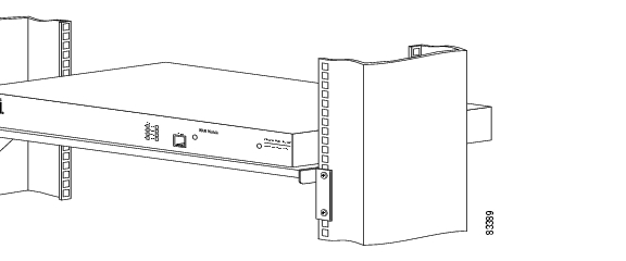
Installing the ONS 15305 in a 19-in. (485-mm) Rack
The shelf assembly is allocated for installation in a 19-in. (485-mm) rack.
Note
Step 1
Step 2
Step 3
Step 4
Figure 1 Front Face-Out in a 19-in. Rack
Figure 2 Connector Array in Front in a 19-in. Rack
Installing 48 V Power and Ground to the ONS 15305
The power needs to be properly installed and grounded for operation of the ONS 15305. Figure 3 shows the location of the 48V connector. The ONS 15305 cabinet shall always be tied to a suitable earth refernce potential as described in Install External Ground to the ONS 15305. The 48V power interface of ONS 15305 is galvanically insulated from the cabinet and the postive pole of the 48V supply (0 VDC) shall always be connected to the same earth potential at the station battery, PDP side. Use the following procedure to install power and ground to the ONS 15305:
Warning
Figure 3 Location of the Power Connector on the ONS 15305 Faceplate (Connector Array)
Step 1
Step 2
Table 1 Power Wire Colors and their Function
Brown
GND
Blue
-48 VDC
Black
-48 VDC
Green/yellow
0V
Note
Note
Install the ONS 15305-AC 230V Power
The following procedure explains how to install ONS 15305 AC power connections.
Figure 4 220-240VAC Module
Warning
Warning
Warning
Caution
AC 230V Module Not Installed in ONS15305
Warning
Power On
Warning
Step 1
Step 2
Power Off
Warning
Caution
Step 1
Step 2
Step 3
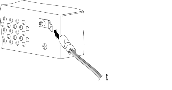
Install External Ground to the ONS 15305
It is vital that the ONS 15305 cabinet is properly grounded.
When installed in a rack, the ONS 15305 cabinet will be tied to the rack reference potential through the mounting brackets (earth, ground potential).
Note
When not installed in a rack, the cabinet can be tied to an earth reference potential via the ground connector of the power supply plug as shown in Figure 3 or by mounting an extra connector to one of the cabinet screws as in Figure 6.
Figure 5 Ground Connector Position on the ONS 15305
Install the Ground Connector
Step 1
Step 2
Step 3
Step 4
Step 5
Step 6
Figure 6 Connection of the Ground Cable with a Crimp Tool
Installation of Service Modules
This section describes installation procedures that are common and independent of Service module type.
For details on each Service modules see separate chapters. Interconnections and cabling are described in "Interconnections and Cable Handling" section.
It is possible to freely mix the four interface modules. There are no fixed positions for specific modules.
Note
Insertion or withdrawal of new modules does not affect the other modules. No manual configuration is needed, if a module is replaced with a module of the same type.
It is possible to protect a module by adding a redundant module in the chassis.
All modules store inventory data in non-volatile memory. The inventory data is accessible from the system controller and the management system.
All modules contain a LED that indicates the status of the module. The LED is green when the module is active. The LED is red if the module is failed. The LED is extinguished when the module is deactivated.
All modules support hot insertion and removal. When the module is replaced the switch must be activated and then the MOD FAIL LED must be extinguished before the module is removed. It is also possible to deactivate the module from the CiscoEdgeCraft terminal. A special tool, the Card Extraction Tool ( Figure 7) is needed to remove the module.
Figure 7 Card Extraction Tool
The following Service modules are described in separate chapters in the Cisco ONS15305 Installation and Operations Guide:
•
•
•
•
•
•
•
•
•
•
•
•
Interconnections and Cable Handling
Install the ONS 15305 Fiber Cable
Caution
To install fiber-optic cables in the ONS 15305, connect a fiber cable with LC connector type to the transmit and receive ports of the transmission system. On the ONS 15305 module, the transmit and receive ports are located at the connector array of the unit. The receive port is named IN and the transmit port is named OUT.
Cisco recommends that you label the transmit and receive fiber (before installation) to and from the optical transmission system at each end of the fiber span to avoid confusion with cables that are similar in appearance.
Warning
Warning
Warning
Connect the Fiber Cable
Step 1
Step 2
Step 3
Step 4
Step 5
Install the ONS 15305 Electrical Cable
Caution
To install electrical connection cables in the ONS 15305, connect the electrical cable with the corresponding ports of the transmission system. On the ONS 15305 module, the electrical ports are located at the connector array of the system. Cisco recommends that you label the electrical cable at each end before installation to avoid confusion with cables that are similar in appearance.
Caution
Connect the Electrical Cables
Step 1
Step 2
Step 3
Warning
Installation Checklist for ONS 15305
The following list is an installation checklist. Use this list as a reference when performing an installation. For detailed installation instructions, refer to the Cisco ONS 15305 Installation and Operations Guide. To check the installation, verify the following items:
•
•
•
•
•
•
•
•
Note
10 ONSCLI - Command Line Interface
Introduction to ONSCLI
ONSCLI is a line-oriented ASCII-based management interface to ONS 15305, by means of which simple commands—possibly with parameters—may be issued to access or modify the ONS 15305 configuration.
Commissioning of IP Address via VT100 Interface
A local terminal with VT100 emulation is required during the first commissioning of the network element in order to set up the necessary communications parameters enabling access to the element via Cisco Edge Craft over the Management Port. After the first commissioning, the VT100 interface can be used for modifying the communications parameters and perform some status checks of the network element. The VT100 interface is password protected.
Accessing ONSCLI (Command Line Interface)
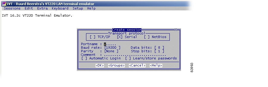
The ONSCLI is accessed via the VT100-port or via an IP connection (Telnet). The serial connection communications parameters are fixed ( Table 2). VT100 terminal codes are used.
Table 2 EIA/TIA-232 Parameters
Speed
19200 bps
Data bits
8
Parity
None
Stop bits
1
Flow control
None
The VT100-port (Console port) for the ONS 15305 is provided using a RJ-45 connector. The cable for connecting the VT100-port to the serial-port on the PC are provided.
Invoke ONSCLI
Step 1
Step 2
Step 3
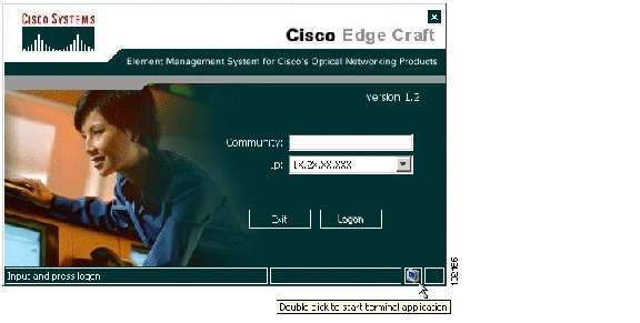
Figure 8 Logon Window
Step 4
Figure 9 Start Window
Step 5
Step 6
>ONSCLI--------------------------------------------------ONS 15305 Command Line Interface--------------------------------------------------Enter ONSCLI password: ******ONSCLI>Step 7
IP-Configuration(Management-Port):Show-Current-Alarms:Community-handler:Exit:It is sufficient to type leading characters of the command name to avoid ambiguity - the same applies to keywords.
Note
The management port IP address is a compulsory parameter, and must be specified by you. All the other parameters (except default gateway) are defaulted to pre-defined values if they are not specified.
Incorrect password
Each password characters is echoed as '*'. An incorrect password is rejected with the message:
invalid passwordand the password prompt is re-issued.
Exit
The Exit command is used to terminate an ONSCLI session. The ONSCLI session will be automatically terminated after a period of 30 minutes of inactivity. ONSCLI does not accept simultaneous sessions.
An authorized ONSCLI user obtains full access rights to the available management information.
Syntax Rules
An ONSCLI command line begins with a prompt (issued by ONSCLI), which serves to indicate the current position in the command hierarchy.
An ONSCLI command is issued by typing the command followed by ENTER. Optionally, and only at the lowest level in the command hierarchy, one or more parameters may also be supplied. These are identified by keywords. The command name, parameter keywords and parameter values are delimited by one or more spaces.
Note
Some commands (in particular Show) may potentially produce many lines of output. After a predetermined number of lines of output in response to a single command, the user is prompted to enter y(es) or n(o) to continue the output. The line number limit is defined with the DISPLAY-LINES parameter to the Command-Line-Interface command.
Basic Command Syntax
A basic command has the following syntax:
Example 1 Basic Command Syntax
<basic command> ::= [<path>]<command> [<parameter>]... <CR><path> ::= [\]<command\>[<command>\]...<command> ::= <command name> | ..<parameter> ::= <spaces> <keyword>=<value> | ?<value> ::= <integer> |<choice> |<IP address> |<string> |<MAC address> |<NSAP address> |<time> |<date> |<KLM> |<portList> |<port><NSAP address> ::= <area address>:<system id>:<selector><portList> ::= <port>[,<port>]..<areaAddressList> ::= <area address>[,<area address>]...where:
<spaces> is a string of one or more ASCII spaces;<integer> is a decimal integer in the range [m:n], where the values m and n are context-dependent;<choice> is a literal string, whose permissable values and their significance are context-dependent and may be obtained by using the help ("?") parameter;<IP address> is an IP address of the form ddd.ddd.ddd.ddd, where d is a decimal digit. Leading zeroes in each ddd may be omitted;<string> is a string of graphical ASCII characters, excluding quotation marks ("). If the string contains one or more spaces, then it MUST be enclosed in quotation marks. The maximum length of the string is context-dependent;<MAC address> is exactly 12 hexadecimal digits;<time> is a time-of-day of the form hh:mm:ss, where h, m and s are decimal digits;<date> is a date of the form dd/mm/yy, where d, m and y are decimal digits;<KLM> is a string of the form k.l.m, where k is a decimal digit in the range [1:3], l is a decimal digit in the range [1:7], and m is a decimal digit in the range [1:3].<port> is a decimal integer;<area address> is a hexadecimal string;<system id> is a hexadecimal string;<selector> is a hexadecimal string;The Help Command
The help command "?" will display all available commands at the current level, each with a short description, for example, typing "?" at the root level will list the commands which are available at this level.
Command Hierarchy
In the command hierarchy, the lowest level is represented by a basic command with one or more parameters.
If the help parameter "?" is supplied (excluding the quotation marks), then any other parameters are ignored and the basic command usage appears.
Table entries are accessed by introducing an additional command level giving access to the entire table. At this lowest level, the command Add (with the index and required table entries as parameters) may be used to add an element to the table and Edit to replace an existing element in the table - if these operations are permitted on the table.
Similarly the Remove command (with the entry index as parameter) may be used to remove an existing element from the table, if this is permitted.
The Show command (with an entry index as parameter) will display the specified table entry. If no parameter is supplied with the Show command, the current contents of the entire table will appear.
11 Initial Configuration
By following the guidelines below you can configure the ONS 15305.
Important Commands
Follow the steps in this chapter to perform initial configuration of the ONS 15305. The most important tasks involved in initial configuration of ONS 15305 are:
•
•
Configure Community-handler
The following example shows how to set community for a default user. If setting community for a specific user, the corresponding IP address must be entered instead of 0.0.0.0
Step 1
Step 2
Step 3
Step 4
Add: Add Community entryEdit: Edit Community entryRemove: Remove Community entryShow: Show Community entryExit:ONSCLI>Community-handler\Step 5
Step 6
MANAGER: 0.0.0.0COMMUNITY: publicACCESS: superTRAPS: disableONSCLI>Community-handler\Assign an IP Address
Step 1
Usage:
IP-Configuration(Management-Port)
[IP-ADDRESS=<IP address>][SUBNET-MASK=<IP address>][DEFAULT-GATEWAY=<IP address>]Available independent of router license
[MODE=<notUsed|ip|clnp|ipAndClnp>]Management mode for the management port
|clnp|ipAndClnp| only with OSI licenseONSCLI>ipIP-ADDRESS: 10.20.47.131SUBNET-MASK: 255.255.254.0DEFAULT-GATEWAY: 10.20.47.254MODE: ipSTATUS: upManagement port StatusONSCLI>Set the IP Address to the Management Port
Step 1
--- Change IP address, are you sure (y/n)? YIP-ADDRESS: 192.168.2.2SUBNET-MASK: 255.255.255.252DEFAULT-GATEWAY: 192.168.2.1Change Passwords
By this command, TELNET and ONSCLI passwords can be changed. Both passwords can be changed in the same command or they can be changed individually.
Step 1
Usage:
Change-Passwords
[ONSCLI -PASSWORD=<string[6:12]>][TELNET-PASSWORD=<string[6:12]>]Further Configuration of ONS15305
Please see the CiscoEdgeCraft Software Guide for instructions related to further configuration and the Cisco ONS 15305 Installation and Operations Guide for details concerning the equipment.
Recommended Order
•
•
•
•
•
•
•
•
•
•
•
•
•
•
![]()
![]()
![]()
![]()
![]()
![]()
![]()
![]()
Posted: Fri Sep 14 09:02:06 PDT 2007
All contents are Copyright © 1992--2007 Cisco Systems, Inc. All rights reserved.
Important Notices and Privacy Statement.