|
|

Table Of Contents
Cisco ONS 15302 Quick Installation Guide
Cisco Product Security Overview
Reporting Security Problems in Cisco Products
Obtaining Technical Assistance
Cisco Technical Support Website
Definitions of Service Request Severity
Obtaining Additional Publications and Information
DC Power Disconnection Warning
Installation Materials for ONS 15302
Installing the ONS 15302 in a 19-in. (485-mm) Rack
Installation in Restricted Access Locations
Installing 48-V Power and Ground to the ONS 15302
Install External Ground for 230 V Supply to the ONS 15302
Installing 230-V Power to the ONS 15302
Installing Fiber Patch Cords on the ONS 15302
Installing Electrical Cables to the ONS 15302
Installation Checklist for ONS 15302
ONSCLI—ONS 15302 Command Line Interface
Quick Start Guide
Cisco ONS 15302 Quick Installation Guide
Release 2.0
January 2005
1 Obtaining Documentation
Cisco documentation and additional literature are available on Cisco.com. Cisco also provides several ways to obtain technical assistance and other technical resources. These sections explain how to obtain technical information from Cisco Systems.
Cisco.com
You can access the most current Cisco documentation at this URL:
http://www.cisco.com/univercd/home/home.htm
You can access the Cisco website at this URL:
You can access international Cisco websites at this URL:
http://www.cisco.com/public/countries_languages.shtml
Documentation DVD
Cisco documentation and additional literature are available in a Documentation DVD package, which may have shipped with your product. The Documentation DVD is updated regularly and may be more current than printed documentation. The Documentation DVD package is available as a single unit.
Registered Cisco.com users (Cisco direct customers) can order a Cisco Documentation DVD (product number DOC-DOCDVD=) from the Ordering tool or Cisco Marketplace.
Cisco Ordering tool:
http://www.cisco.com/en/US/partner/ordering/
Cisco Marketplace:
http://www.cisco.com/go/marketplace/
Ordering Documentation
You can find instructions for ordering documentation at this URL:
http://www.cisco.com/univercd/cc/td/doc/es_inpck/pdi.htm
You can order Cisco documentation in these ways:
•
Registered Cisco.com users (Cisco direct customers) can order Cisco product documentation from the Ordering tool:
http://www.cisco.com/en/US/partner/ordering/
•
2 Documentation Feedback
You can send comments about technical documentation to bug-doc@cisco.com.
You can submit comments by using the response card (if present) behind the front cover of your document or by writing to the following address:
Cisco Systems
Attn: Customer Document Ordering
170 West Tasman Drive
San Jose, CA 95134-9883We appreciate your comments.
3 Cisco Product Security Overview
Cisco provides a free online Security Vulnerability Policy portal at this URL:
http://www.cisco.com/en/US/products/products_security_vulnerability_policy.html
From this site, you can perform these tasks:
•
•
•
A current list of security advisories and notices for Cisco products is available at this URL:
If you prefer to see advisories and notices as they are updated in real time, you can access a Product Security Incident Response Team Really Simple Syndication (PSIRT RSS) feed from this URL:
http://www.cisco.com/en/US/products/products_psirt_rss_feed.html
Reporting Security Problems in Cisco Products
Cisco is committed to delivering secure products. We test our products internally before we release them, and we strive to correct all vulnerabilities quickly. If you think that you might have identified a vulnerability in a Cisco product, contact PSIRT:
•
•
Tip
Never use a revoked or an expired encryption key. The correct public key to use in your correspondence with PSIRT is the one that has the most recent creation date in this public key server list:
http://pgp.mit.edu:11371/pks/lookup?search=psirt%40cisco.com&op=index&exact=onIn an emergency, you can also reach PSIRT by telephone:
•
•
4 Obtaining Technical Assistance
For all customers, partners, resellers, and distributors who hold valid Cisco service contracts, Cisco Technical Support provides 24-hour-a-day, award-winning technical assistance. The Cisco Technical Support Website on Cisco.com features extensive online support resources. In addition, Cisco Technical Assistance Center (TAC) engineers provide telephone support. If you do not hold a valid Cisco service contract, contact your reseller.
Cisco Technical Support Website
The Cisco Technical Support Website provides online documents and tools for troubleshooting and resolving technical issues with Cisco products and technologies. The website is available 24 hours a day, 365 days a year, at this URL:
http://www.cisco.com/techsupport
Access to all tools on the Cisco Technical Support Website requires a Cisco.com user ID and password. If you have a valid service contract but do not have a user ID or password, you can register at this URL:
http://tools.cisco.com/RPF/register/register.do
Note
Submitting a Service Request
Using the online TAC Service Request Tool is the fastest way to open S3 and S4 service requests. (S3 and S4 service requests are those in which your network is minimally impaired or for which you require product information.) After you describe your situation, the TAC Service Request Tool provides recommended solutions. If your issue is not resolved using the recommended resources, your service request is assigned to a Cisco TAC engineer. The TAC Service Request Tool is located at this URL:
http://www.cisco.com/techsupport/servicerequest
For S1 or S2 service requests or if you do not have Internet access, contact the Cisco TAC by telephone. (S1 or S2 service requests are those in which your production network is down or severely degraded.) Cisco TAC engineers are assigned immediately to S1 and S2 service requests to help keep your business operations running smoothly.
To open a service request by telephone, use one of the following numbers:
Asia-Pacific: +61 2 8446 7411 (Australia: 1 800 805 227)
EMEA: +32 2 704 55 55
USA: 1 800 553-2447For a complete list of Cisco TAC contacts, go to this URL:
http://www.cisco.com/techsupport/contacts
Definitions of Service Request Severity
To ensure that all service requests are reported in a standard format, Cisco has established severity definitions.
Severity 1 (S1)—Your network is "down," or there is a critical impact to your business operations. You and Cisco will commit all necessary resources around the clock to resolve the situation.
Severity 2 (S2)—Operation of an existing network is severely degraded, or significant aspects of your business operation are negatively affected by inadequate performance of Cisco products. You and Cisco will commit full-time resources during normal business hours to resolve the situation.
Severity 3 (S3)—Operational performance of your network is impaired, but most business operations remain functional. You and Cisco will commit resources during normal business hours to restore service to satisfactory levels.
Severity 4 (S4)—You require information or assistance with Cisco product capabilities, installation, or configuration. There is little or no effect on your business operations.
5 Obtaining Additional Publications and Information
Information about Cisco products, technologies, and network solutions is available from various online and printed sources.
•
http://www.cisco.com/go/marketplace/
•
•
•
http://www.cisco.com/go/iqmagazine
•
•
http://www.cisco.com/en/US/learning/index.html
6 Quick Overview
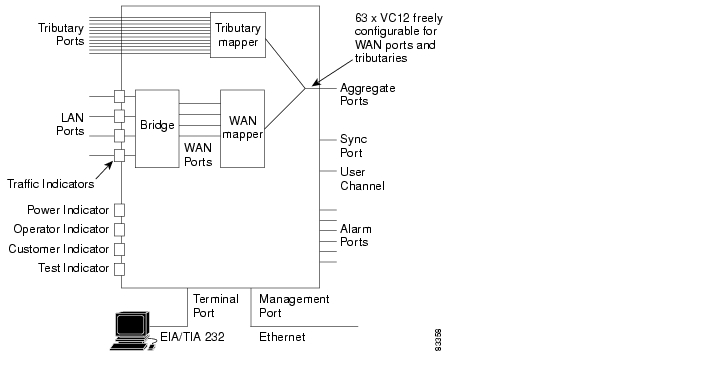
Figure 1 ONS 15302 Functional Overview
The main R1.0 to R2.0 enhancement is the introduction of GFP/LCAS, which is a Ethernet framing standard to transport Ethernet packets in virtual containers through a SDH network. Additionally this edition introduces a new option for management connectivity, which will simplify design and configuration of a network supplied by Cisco. All features in this release is aligned with the new release of ONS 15305.
The ONS 15302 is an Integrated Access Device mainly intended for use in fibre optic networks, but can also be supplied as a hardware option with support for electrical STM-1. The ONS 15302 combine IP- and TDM-traffic, by running IP- along with TDM-channels inside an SDH STM-1 frame structure that can be easily carried across the network. The bandwidth of the IP-channel is configurable up to 100 Mb/s true "wire-speed". The IP part of the ONS 15302 R2.0 consists of a L2/L3 switch.
Each tributary interface (E1) is mapped into a VC-12 container while the WAN traffic can be transported via either nxVC-3 or nxVC12.
The ONS 15302 have room for a plug-in module, which adds more WAN-ports to achieve multiple connections with differentiated bandwidth per customer and/or service.
The ONS 15302 management solution is based on an embedded SNMP agent and a SNMP Craft utility (Cisco EdgeCraft) is supplied with the deliveries of ONS 15302. Minimum required to operate and configure the ONS 15302 is a simple VT100 command line interface (ONSCLI) for direct communication with the embedded SNMP agent.
7 Before Starting
This guide provides basic instructions for installing the Cisco ONS 15302 system. It contains two different parts:
•
•
Use this guide as a general reference when performing an installation.
For detailed installation instructions, refer to the most recent Cisco ONS 15302 Installation and Operations Guide (Release 2.0).
Caution
8 Translated Warnings
DC Power Disconnection Warning
Main Disconnecting Device
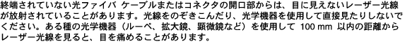
Laser Radiation Warning
Unterminated Fiber Warning
Class 1 Laser Product Warning
9 Installation Materials for ONS 15302
Several items are needed to complete the installation of the ONS 15302. Some of these items are supplied by Cisco and some need to be supplied by the user. The following are the Cisco-supplied materials that are include in the 15302-SHIPKIT= (74-3173-01). The number in parentheses is the quantity of each included item.
•
•
•
•
•
•
•
•
•
•
The following materials, tools, and equipment are recommended but are not supplied with the ONS 15302:
•
•
•
•
•
•
•
•
•
•
•
•
•
•
•
10 Installing the ONS 15302
To install the ONS 15302, complete the following procedures:
1.
2.
3.
4.
5.
6.
8.
Installing the ONS 15302 in a 19-in. (485-mm) Rack
The shelf assembly is allocated for installation in a 19-in. (485-mm) rack. The ONS 15302 is 17.5-in. (445-mm) wide by 9.4-in. (240-mm) deep by 1.7-in. (44-mm) high.
Step 1
Step 2
Step 3
Step 4
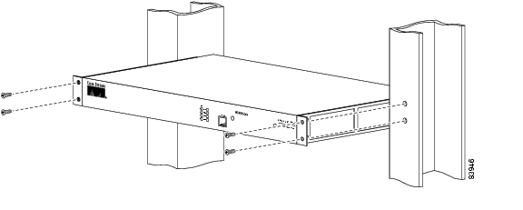
Figure 2 Install the ONS 15302 with the Connector Array in Front in a 19-in. Rack
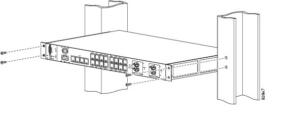
Figure 3 Install the ONS 15302 with the WAN Module in Front in a 19-in. Rack
Note
Installation in Restricted Access Locations
The ONS 15302 can be installed in a restricted access location (RAL) or outside of an RAL.
Definitions
Restricted Access Location
A restricted access location is a site location for equipment where both of the following paragraphs apply:
•
•
SELV Circuits
Safety Extra-Low Voltage (SELV) circuits are ports that have maximum DC working voltage level less than 60 V (42.4 VAC). In addition, the ports must not be connected to telecommunication networks as defined in EN 60950 (see CEI/ IEC 60950-1 2001-10, standard clause 1.2.13.8).
In practice, the electrical cables shall not exit the building. In addition, the electrical cables shall connect to equipment that meets one of the following requirements:
•
•
•
Telecommunication Network
A telecommunication network is a metallically terminated transmission medium intended for communication between equipment that might be located in separate buildings, excluding:
•
•
•
TNV Circuit
A TNV circuit in the equipment to which the accessible area of contact is limited. A TNV circuit is so designed and protected that, under normal operating conditions and single fault conditions (see CEI/IEC 60950-1 2001-10, standard clause 1.4.14), the voltages do not exceed specified limit values.
Installation in Restricted Access Location
After installation in a RAL, such as in a telecommunications center, the ONS 15302 must be properly installed in a rack with brackets or in other ways properly connected to a safety ground. The ONS 15302 48-VDC power must not be powered from a source external to the RAL. The E1 interface used should be limited to SELV.
Installation Outside of a Restricted Access Location
After installation in a non-RAL location, the ONS 15302 48-V power and all communication ports used must be connected to SELV circuits, for example, a port on a personal computer or 10/100-Mbit Ethernet hub/router or other information technology (IT) equipment. The 48-VDC power must not exceed 60 VDC, and must be powered from a certified external power supply unit (PSU) or a battery unit (with no connection to -48 V telecommunications voltage).
The optical ports and 230-VAC power plug have no limitations regarding safety recommendations.
Installing 48-V Power and Ground to the ONS 15302
The power needs to be properly installed and grounded for operation of the ONS 15302. Figure 4 shows the location of the 48-V connector. Use the following procedure to install power and ground to the ONS 15302:
Warning
Warning
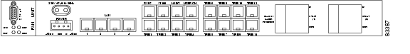
Figure 4 ONS 15302 Faceplate (Connector Array)
Step 1
Step 2
Step 3
Step 4
Step 5
Step 6
Step 7
Note
Note
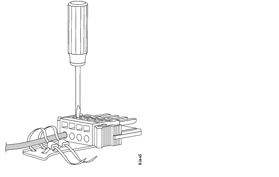
Figure 5 Fixing the Wire into the Connector
Install External Ground for 230 V Supply to the ONS 15302
Note
The ONS 15302 should be grounded to the rack ground via the external ground connector.
The location of the ground connector on the ONS 15302 is shown in Figure 6.
Figure 6 Ground Connector Position on the ONS 15302
Step 1
Step 2
Step 3
Step 4
Step 5
Step 6
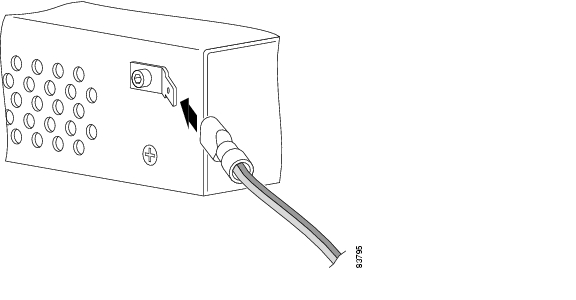
Figure 7 Connecting of the Ground Cable with a Crimp Tool
Installing 230-V Power to the ONS 15302
The ONS 15302 can also be used as a desk version. This means that it is possible to connect the ONS 15302 to a public power supply. Figure 4 shows the location of the 230-V connector.
Warning
Note
Note
Step 1
Step 2
Step 3
Installing Fiber Patch Cords on the ONS 15302
The ONS 15302 is available in two different versions: protected and unprotected. In unprotected mode, transmit and receive fibers from the fiber termination rack are connected to STM-1 port 1. In protected mode, transmit and receive fibers from the fiber termination rack are connected to STM-1 port 1 and port 2, ( Figure 4).
Warning
Warning
Warning
Note
To avoid confusion in the future, label each end of the transmit and receive cables before installation. To install the fiber patch cords, gently push the SC connector into the connector.
For future use (in case of servicing) keep the dust caps in a clean location.
Routing Fiber Patch Cords
After connecting the fibers to and from the fiber termination rack, route the fibers through the rack. Wind the fibers to a loop with a diameter of approximately 3.15 in. (80-mm).
Installing Electrical Cables to the ONS 15302
The ONS 15302 has two different electrical connectors: one DS-9 connector for the alarm interface and 20 RJ-45 connectors for different functions, described in Table 1. The electrical ports on the ONS 15302 are shown in Figure 4.
To avoid confusion in the future, label each end of the cables before installation. To install the electrical cables, gently push the RJ-45 connector into the connector until it snaps in with a click. Screw in the screws from the connector of the alarm cable with a screwdriver.
Routing Electrical Cables
After connecting the cable to the ONS 15302, route the cable through the rack without damage it.
Installation Checklist for ONS 15302
The following list is an installation checklist. Use this list as a reference when performing an installation. For detailed installation instructions, refer to the Cisco ONS 15302 Installation and Operations Guide (Release 2.0). To check the installation, verify the following items:
•
•
•
•
•
•
11 ONSCLI—ONS 15302 Command Line Interface
Introduction to ONSCLI
ONSCLI is a line-oriented ASCII-based management interface to ONS 15302. It is used to issue simple commands—possibly with parameter—to access or modify the ONS 15302 configuration.
Accessing ONSCLI
ONSCLI is accessed via the VT100-port or via an IP connection (Telnet). The serial connection communications parameters are fixed ( Table 2). VT100 terminal codes are used.
Table 2 EIA/TIA-232 Parameters
Speed
19200 bps
Data bits
8
Parity
None
Stop bits
1
Flow control
None
The VT100-port (Console port) for the ONS 15302 is provided using a RJ-45 connector.
Invoke an ONSCLI Session
An ONSCLI session is invoked by typing ONSCLI at the CLI terminal.
User authentication (a password containing between 8 and 12 ASCII characters, with no case sensitivity) is required, as the following session start-up sequence shows:
>>ONSCLI---------------------------------------------------ONS 15302 Command Line Interface---------------------------------------------------Enter ONSCLI password: ******ONSCLI>
Note
Incorrect Password
Each password characters is echoed as *. An incorrect password is rejected with the message:
invalid passwordAfter the password is rejected, the password prompt is re-issued.
Note
An authorized ONSCLI user has full access rights to the available management information.
Exit
The Exit command is used to terminate an ONSCLI session. The ONSCLI session is automatically terminated after a period of 30 minutes of inactivity. ONSCLI does not accept simultaneous sessions.
Syntax Rules
An ONSCLI command line begins with a prompt (issued by ONSCLI), which serves to indicate the current position in the command hierarchy.
An ONSCLI command is issued by typing the command followed by Enter. Optionally, and only at the lowest level in the command hierarchy, one or more parameters can also be supplied. These are identified by keywords. The command name, parameter keywords, and parameter values are delimited by one or more spaces. Command line editing features are listed in Table 3.
Note
ONSCLI Commands are listed in Table 4
Some commands (in particular the show command) can potentially produce many lines of output. After a predetermined number of lines of output in response to a single command, the user is prompted to enter y(es) or n(o) to continue the output. The default line number limit is 23 and maximum is 998. For detailed information about the ONSCLI commands, refer to the Cisco ONS 15302 Installation and Operations Guide (Release 2.0).
Basic Command Syntax
A basic command has the syntax shown in Example 1.
Example 1 Basic Command Syntax
<basic command>::= [<path>]<command> [<parameter>]... <CR><path>::= [\]<command\>[<command>\]...<command>::= <command name> |..<parameter>::= <spaces> <keyword>=<value> |?<value>::= <integer> |<choice> |<IP address> |<string> |<MAC address> |<NSAP address> |<time> |<date> |<KLM> |<portList> |<port><NSAP address> ::= <area address>:<system id>:<selector><portList> ::= <port>[,<port>]..<areaAddressList> ::= <area address>[,<area address>]...where:<spaces> is a string of one or more ASCII spaces;<integer> is a decimal integer in the range [m:n], where the values m and n are context-dependent;<choice> is a literal string, whose permissible values and their significance are context-dependent and may be obtained by using the help (?) parameter;<IP address> is an IP address of the form ddd.ddd.ddd.ddd, where d is a decimal digit. Leading zeroes in each ddd may be omitted;<string> is a string of graphical ASCII characters, excluding quotation marks ("). If the string contains one or more spaces, then it MUST be enclosed in quotation marks. The maximum length of the string is context-dependent;<MAC address> is exactly 12 hexadecimal digits;<time> is a time-of-day of the form hh:mm:ss, where h, m and s are decimal digits;<date> is a date of the form dd/mm/yy, where d, m and y are decimal digits;<KLM> is a string of the form k.l.m, where k is a decimal digit in the range [1:3], l is a decimal digit in the range [1:7], and m is a decimal digit in the range [1:3].<port> is a decimal integer;<area address> is a hexadecimal string;<system id> is a hexadecimal string;<selector> is a hexadecimal string;For a complete overview of the ONSCLI command hierarchy, please refer the Cisco ONS 15302 Installation and Operations Guide (Release 2.0).
The Help Command
The help command (?) displays all available commands at the current level, each with a short description. For example, typing? at the root level lists the commands that are available at this level, as shown in Example 2.
Example 2 Help Command
ONSCLI>?*** current menu path:<root>*** valid commands:Device: Device configurationPorts: Port propertiesBridge: Bridge/Spanning Tree Protocol settingsRouter: Router configurationSecurity: Security settingsStatistics: Performance monitoring and statisticsServices: Utility functionsAlarms: Current alarms and alarm historyQoS: Quality of serviceRunning: Show Running ConfigExit: Exit from ONSCLICommand Hierarchy
In the command hierarchy, the lowest level is represented by a basic command with one or more parameters.
If the help parameter (?) is supplied, then all other parameters are ignored and the basic command usage is displayed.
Table entries are accessed by introducing an additional command level giving access to the entire table. At this lowest level, the Add command (with the index and required table entries as parameters) can be used to add an element to the table and the Edit command can be used to replace an existing element in the table (if these operations are permitted on the table).
Similarly the Remove command (with the entry index as a parameter) can be used to remove an existing element from the table if this is permitted.
The Show command (with an entry index value as a parameter) displays the specified table entry. If no parameter is supplied with the Show command, the current contents of the entire table is displayed.
ONSCLI Error Messages
SNMP Errors
The general ONSCLI output string for SNMP errors is MIB access error. Additional SNMP error information might be printed depending on the return code ( Table 5).
Input Errors
Error messages due to mistyping or incorrect ONSCLI input format are shown in Table 6.
12 Initial Configuration
By following the guides below you should be able to do the most important configurations of ONS 15302.
Factory Preconfiguration
Since the ONS 15302 is a flexible product with a lot of possible network applications, the factory preconfiguration is limited when delivered. Ethernet ports 1 to 5 are members of VLAN 1, the aggregate (STM-1) is enabled, and one VC-12 container is allocated to the Ethernet WAN (port number 5). In addition, an entry in the SNMP community table is preconfigured so that when an IP address is assigned, the ONS 15302 is able to take advantage of the GUI element manager. This configuration persists, regardless of whether the WAN module is inserted or not.
Example 3 Restore Factory Settings
The factory settings can also be restored by use of the ONSCLI command:
ONSCLI>Device\Factory-ResetThis command will only restore the factory settings properly if the configuration is cleared before the command is given. To make sure reset configuration is done, following line appears on the system terminal when Factory-Reset command is given:
Are device configuration) erased (y/n)?Important Commands
Follow the steps in this section to perform initial configuration of the ONS 15302. The following tasks are the most important tasks involved in the configuration of an ONS 15302:
–
–
–
–
Assign an IP Address to the ONS 15302
The ONS 15302 supports remote management solutions by the means of Telnet and SNMP.The possibilities as regards connectivity can be rather advanced for the ONS 15302 so the only explained solution in this document is when directly connected the management-port (MNGT). For more information please refer the Cisco ONS 15302 Installation and Operations Guide (Release 2.0).
To achieve one of the above mentioned management solutions it is necessary to assign an IP-address, subnet-mask and if required a default-gateway address must be defined.
System Mode
In ONS 15302 R2.0 an additional management mode, system mode is added.The System mode has two options, ip and ipunnumbered.
ONSCLI>...\Management-Configuration\sys?Usage:System-Mode[SYSTEM-MODE=<ip|ipunnumbered>]System Mode - IP
ONSCLI>...\Management-Configuration\sys sys=ipChange management configuration, are you sure? (y/n)?Example 4 Assign an IP-address:
If system mode is ip the command for IP configuration is:
ONSCLI>Device\Management-Configuration\Management-Port\IP-Configuration IP-ADDRESS=193.69.136.104,
SUBNET-MASK=255.255.255.0.
System Mode - IP Unnumbered
ONSCLI>...\Management-Configuration\sys sys=ipunnumChange management configuration, are you sure? (y/n)?
Example 5 Assign an IP-address:
If system mode is ipunnumbered the command for IP configuration is:
ONSCLI>Device\Management-Configuration\IP-Configuration IP-ADDRESS=193.69.136.104, SUBNET-MASK=255.255.255.0.Define SNMPv1 Community
Factory pre-configured community:
Manager: 0.0.0.0Community: publicAccess: SuperTraps: DisabledThis is an insecure community, which enables all managers regardless of the IP-address for the SNMP manager to access the device with the community string "public".
To add your own community string please use the following command:
ONSCLI>Security\Community-Table\add manager=10.0.0.20 community=admin access=super traps=enable
"Enter"
Erase a Community String
To remove a community string the following command can be used:
ONSCLI>Security\Community-Table\remove manager=0.0.0.0 community=public
"Enter"
Note
![]()
![]()
![]()
![]()
![]()
![]()
![]()
![]()
Posted: Tue Jan 8 08:10:26 PST 2008
All contents are Copyright © 1992--2008 Cisco Systems, Inc. All rights reserved.
Important Notices and Privacy Statement.