|
|

Table Of Contents
3.2 Reference Optical Performance of 1.25 GBIC Interfaces
3.3 Broadcast Node FlexLayer Configuration
3.3.1 In-Line Drop Node FlexLayer Configuration
3.4 Drop and Broadcast Node FlexLayer Configuration
3.5 Line Amplifier Node FlexLayer Configuration
Application Overview
3.1 Application
The purpose of the FlexLayer Asymmetric DWDM system of components is entirely focused on uni-directional Video on Demand (VoD) applications. These applications are unique in that they require only one channel, the OSC (if used), to be bi-directional. The other channels are uni-directional. The ONS15216 R2.1 channel plan (32 channels, 100 GHz spacing) is used in this release. Table 3-1 shows how the FlexLayer A/D modules are grouped in relation to the supported channels.
The ONS 15216 FlexLayer system is designed to support the DWDM transmission of 1.25 GBIC interfaces. The reference performance of these interfaces are reported in Table 3-2. The ONS 15216 FlexLayer system deploys the ONS 15216 EDFA2 for optical amplification of the signal.
Table 3-2 Reference Optical Performance of 1.25 GBIC Interfaces
1.25 Gb/s
N/A
No
Average
10-12
20 dB
-28 to -7 dBm
0 to +4 dBm
1 Measured on 0.1 nm Resolution Bandwidth.
Figure 3-1 illustrates a typical ONS 15216 FlexLayer Architecture.
Figure 3-1 A Typical ONS 15216 FlexLayer Architecture
These unidirectional channels are transported from one side and available at each and every remote site. The channel requirements at that site can be de-multiplexed as necessary. In the ONS 15216 FlexLayer architectures, nodes are designed for specific roles. These roles include:
•
Head End Node
•
•
•
•
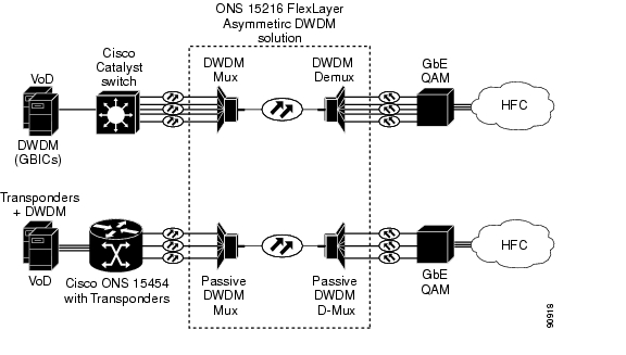
Figure 3-2 shows the required Cisco VoD GigE transport solutions. These solutions at the time of this writing are not yet available (see PLM for release information). In reference to Figure 3-2, the upper most solution uses the Cisco Catalyst 45XX w/ITU GBICs. The lower most solution uses the Cisco ONS 15454 w/GE transponders.
Figure 3-2 Cisco GigE VoD Transport Solutions
The ONS 15216 FlexLayer Network Design Tool will soon be available to help create networks and establish requirements for ONS 15216 unidirectional applications. Look for a link to this tool on the ONS 15216 product web page, http://www.cisco.com/en/US/products/hw/optical/ps1996/ps1999/index.html.
3.2 Reference Optical Performance of 1.25 GBIC Interfaces
The Head End node is a terminal node where all the channels passing through it are transmitted. This node performs a complete multiplexing of the channels. Typical equipment layouts include the linear and parallel configurations.
3.2.1 Linear Layout
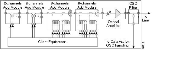
The basic elements of the node are the n-channel add/drop modules used in the add arrangement. They collect traffic from the client equipment and aggregate it in a DWDM composite signal on a single fiber. Modules are connected in series (i.e. the output of a card to the input of another one) to build a linear configuration. This configuration allows the highest degree of flexibility for a future no traffic-affecting upgrade of the terminal site channel capacity.
When new channels are added to the multiplexing capacity, the output port of the new module is connected to the input port of the first module of the chain. An optical amplifier can be inserted at the output of the last card to recover for the node losses. The OSC filter can be inserted at the node output to allow OSC capabilities in conjunction with the client equipment.
Figure 3-3 shows a flexlayer linear head end configuration.
Figure 3-3 A FlexLayer Linear Head End Configuration
3.2.2 Parallel Layout
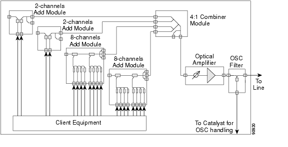
The parallel layout uses a x:1 combiner module to collect output signals from add modules. The combiner limits the maximum number of add modules that can be deployed in the node, but achieves a better channel power equalization when compared to the linear layout. The VOA module is added to fine tune the channel sub-band equalization. An Optical amplifier can be introduced at the output of the combiner to recover for the network element insertion loss. The OSC filter can be inserted at the node output to allow OSC capabilities in conjunction with the client equipment. Figure 3-4 shows a flexlayer parallel head end configuration.
Figure 3-4 FlexLayer Parallel Head End Configuration
3.3 Broadcast Node FlexLayer Configuration
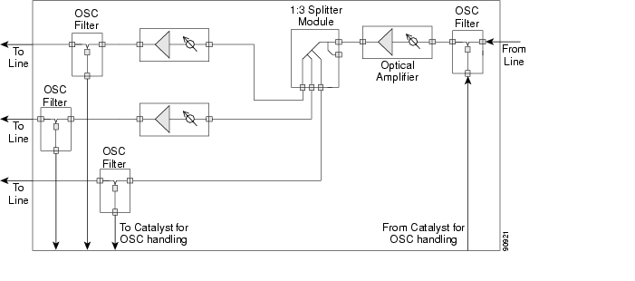
The broadcast node has one input optical port and two or more optical output ports. The node replicates the input signal spectrum at the output ports, thus allowing a wider distribution of the data traffic. Optical amplifiers can be connected to the input or to one or more of the output ports to recover for node insertion losses or to allow further propagation. It must be noted that the optical amplifiers are both optional, and their presence depends on the network. The OSC filters can be inserted at the node input and at the node output ports to allow OSC capabilities in conjunction with the client equipment. Figure 3-5 shows how a flexlayer broadcast node could be set up.
Figure 3-5 FlexLayer Broadcast Node Configuration
3.3.1 In-Line Drop Node FlexLayer Configuration
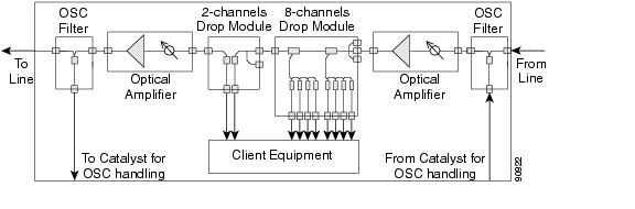
The drop node performs the extraction of some channels from the composite signal leaving remnant channels available on the output port. The client equipment is connected to the drop ports of the drop modules. Each module output port is connected to the input port of another module in a chain arrangement. The channel power and the receivers' dynamics define the order of the modules. The input port of the first module is the input port of the node. An optical amplifier can be inserted here to recover for insertion losses. The output port of the last drop module is the output port of the network element. An optical amplifier can be inserted here to recover for insertion losses.
Note
If at least one amplifier is present, the OADM node is called an active drop node, otherwise the node is called a passive node.
If an optical amplifier is inserted at the input port of the node, the VOA module must be used between some of the drop modules and the client equipment to avoid damage of the client equipment. The OSC filters can be further inserted at the node input and at the node output to allow OSC capabilities in conjunction with the client equipment. If the output port is unconnected the node acts as a terminal node. Figure 3-6 shows how a typical flexlayer in-line drop node configuration can be layed out.
Figure 3-6 FlexLayer In-Line Drop Node Configuration
3.4 Drop and Broadcast Node FlexLayer Configuration
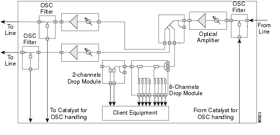
The drop and broadcast node performs the extraction of some channels from the composite DWDM signal and replicates (regenerates) all the channels on the output ports. The client equipment is connected to the drop ports of the drop modules. Each flexlayer module output port is connected to the input port of another flexlayer module in a chain arrangement. The input port of the first flexlayer module is the input port of the node. An optical amplifier can be inserted here to recover for insertion losses. The output port of the last add flexlayer module is the output port of the network element. An optical amplifier can be inserted here to recover for insertion losses.
Note
If at least one amplifier is present the OADM node is called an active drop node, otherwise the node is called a passive node.
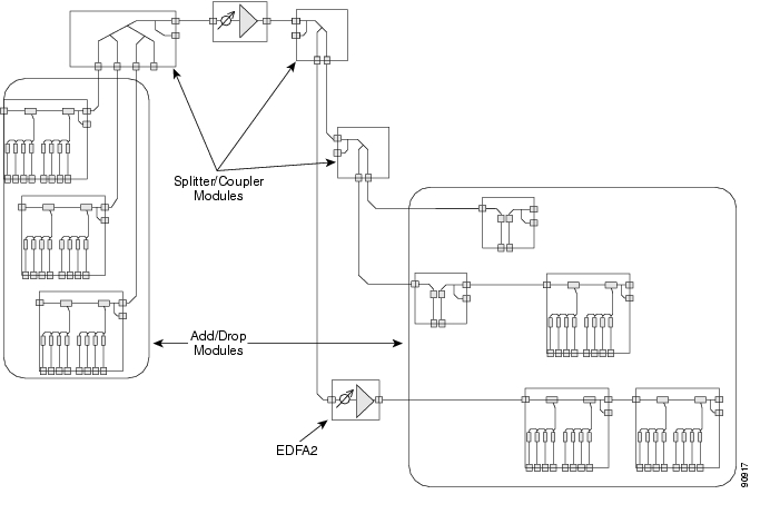
If an optical amplifier is inserted at the input port of the node, the VOA module must be used between some of the drop modules and the client equipment to avoid damage of the client equipment. The OSC filters can be inserted at the node input and at the node output ports to allow OSC capabilities in conjunction with the client equipment. Figure 3-7 shows how a typical flexlayer drop and broadcast node configuration can be layed out.
Figure 3-7 FlexLayer Drop and Broadcast Node Configuration
3.5 Line Amplifier Node FlexLayer Configuration
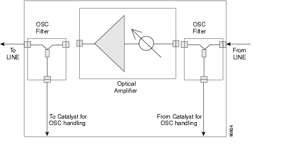
The line amplifier node performs signal power recover in order to achieve a longer transmission distance. It is composed of optical amplifiers only. The OSC filters can be inserted at the node input and at the node output ports to allow OSC capabilities in conjunction with the client equipment. Figure 3-8 shows a flexlayer line amplifier node configuration.
Figure 3-8 FlexLayer Line Amplifier Node Configuration
![]()
![]()
![]()
![]()
![]()
![]()
![]()
![]()
Posted: Sun Apr 2 03:37:42 PDT 2006
All contents are Copyright © 1992--2006 Cisco Systems, Inc. All rights reserved.
Important Notices and Privacy Statement.