|
|

Table Of Contents
Unpack and Verify the Equipment
Install the ONS 15216-ID-50 Module
Fiber Optic Connector Cleaning and Maintenance
Install and Route Fiber-Optic Cables
Cisco ONS 15216 FlexLayer Compatibility Specifications
Where to Find Safety and Warning Information
Cisco Optical Networking Product Documentation CD-ROM
Cisco Product Security Overview
Reporting Security Problems in Cisco Products
Obtaining Technical Assistance
Cisco Technical Support & Documentation Website
Definitions of Service Request Severity
Obtaining Additional Publications and Information
Installing and Operating the Cisco ONS 15216
50 GHz/100GHz Optical Interleaver and De-interleaver Module
Introduction
This document explains how to install and operate the Cisco ONS 15216 50 GHz/100 GHz Optical Interleaver and De-Interleaver module used in the Cisco ONS 15216 FlexLayer four-slot shelf assembly. The FlexLayer product provides 50 GHz of channel spacing in Dense Wavelength Division Multiplexing (DWDM) systems.
Safety Information
Before you install, operate, or service the Cisco ONS 15216 50 GHz/100 GHz Optical Interleaver and De-interleaver module (hereafter referred to as the ONS 15216-ID-50), read the Cisco Optical Products Regulatory Safety and Compliance Information document for important safety information you should know before working with the system.
The ONS 15216-ID-50 is compliant with GR 1089, UL60950 /CSA 22.2 No. 60950-00, and IEC 60950.
Laser Radiation Emission Restrictions
The Class 1M Laser safety and warning label is affixed to the ONS 15216-ID-50 module and indicates that the product should never be used or installed in an optical network with emissions higher than Class IM.
Warning
Class 1M laser radiation when open. Do not view directly with optical instruments. Statement 1053
Laser Safety During Operation
Warning
Electrical Safety
Note
Product Description
The ONS 15216-ID-50 is a C-band 50 GHZ/100 GHz module that operates in the Cisco ONS 15216 FlexLayer four-slot shelf assembly in 50-GHz channel spacing DWDM systems. The ONS 15216-ID-50 module can interleave and de-interleave signals and extract a fraction of the signals for monitoring purposes. These are some of the module's applications and uses:
•
•
•
Features
The ONS 15216-ID-50 is a modular component that provides signal interleaving and de-interleaving in 50-GHz channel spacing DWDM systems. It is optically and electrically passive and requires no temperature control. It uses fused fiber coupler technologies and a birefringent crystal technology platform. The module's ultra-low dispersion coupled with the wide bandwidth (Wideband 100 GHz) reduces the concerns of dispersion accumulation and bandwidth narrowing, making the ONS 15216-ID-50 ideal for Multi-OADM Metro ring or mesh-based architectures.
Some of the ONS 15216-ID-50 module's operating features include:
•
•
•
•
•
•
Functional Description
The ONS 15216-ID-50 module increases capacity by combining two optical data streams into a single, more densely spaced stream. The module can be used in Mux mode to combine two 100-GHz optical signal streams into one 50-GHz stream, or in Demux mode to separate the 50-GHz stream into two 100-GHz streams.
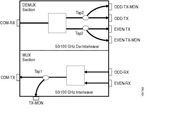
The 15216-ID-50 is a bidirectional module in which the Mux and Demux functions are implemented in two different sections to enable signals flowing in opposite directions to be managed separately. This design is illustrated in Figure 1.
Figure 1 Module Design
The interleaver in the Mux section combines the even and odd channel signals at 100 GHz spacing (EVEN-RX and ODD-RX ports, respectively) into the 50 GHz channel spacing signal. The tap coupler enables aggregate 50-GHz-spaced transmitted optical channel spectrum monitoring at the output (TX-MON port).
The de-interleaver in the Demux section separates the 50-GHz channel spacing signal into even and odd channel signals of 100-GHz spacing (EVEN-TX and ODD-TX ports, respectively). The tap coupler on each of the two Demux paths enables even (EVEN-MON port) and odd (ODD-MON port) channel signal spectrum monitoring.
Channel Wavelength Allocation
The ONS 15216-ID-50 channel plan is shown in .
Installation
This section explains how to unpack, verify, and install the ONS 15216-ID-50 module; clean and maintain the fiber-optic connectors; and install and route fiber-optic cable.
Unpack and Verify the Equipment
Step 1
•
•
•
Step 2
Step 3
•
•
•
•
Install the ONS 15216-ID-50 Module
The ONS 15216-ID-50 module operates in the Cisco ONS 15216 FlexLayer four-slot shelf assembly. The FlexLayer shelf can be installed anywhere in the rack (in other words, above or below the DWDM generating equipment), according to local site practice.
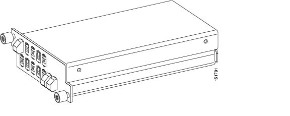
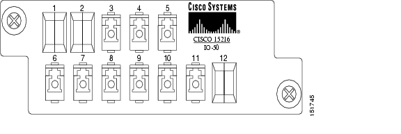
The 15216-ID-50 module is passive and requires no power cabling or connections. All connectors are on the front panel, which is equipped with LC/UPC bulkhead adapters. Fiber-optic cables equipped with the corresponding (LC/UPC) connector type are used. The module port numbers are labelled on the front panel, and port assignments are provided in Figure 2.
For more information about the FlexLayer product, see the Cisco ONS 15216 FlexLayer User Guide.
Figure 2 ONS 15216-ID-50 Module
Install the 15216-ID-50 Module in the ONS 15216 FlexLayer Shelf
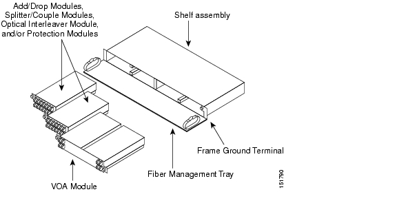
The FlexLayer shelf assembly is 1 RU high and can be mounted in a 19- or 23-inch rack (2-way mounting brackets). The shelf assembly is houses four Add/Drop, Splitter/Combiner FlexLayer, or Interleaver/De-Interleaver modules, or two VOA FlexLayer modules. Figure 3 shows the FlexLayer shelf assembly and FlexLayer modules, including the ONS 15216-ID-50.
Figure 3 ONS 15216-ID-50 Installation in a Cisco ONS 15216 FlexLayer Shelf Assembly
Step 1
Step 2
Step 3
Caution
Port Assignments
Table 2 lists the connector position and the type of connector used for each optical port. All connectors are on the front panel, which is equipped with LC adapters.
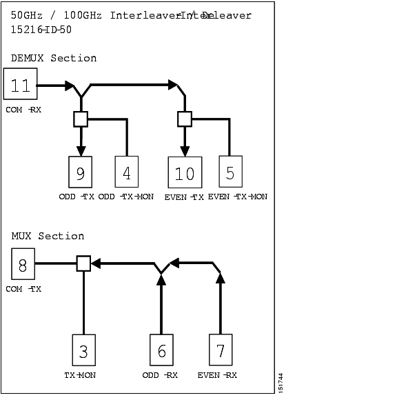
Figure 4 shows the module port numbers and labels.
Figure 4 Port Numbers and Labels
Figure 5 shows the corresponding optical ports on the front panel.
Figure 5 Front Panel Optical Ports
Fiber Optic Connector Cleaning and Maintenance
Connector cleaning is required to maintain the performance of fiber-optic circuits. It is important that both the LC/UPC connector at the end of the fiber-optic cable and the mating bulkhead adapter on the front panel of the ONS 15216-ID-50 are clean before the connection is made.
Warning
The following warning applies to disposal of chemicals and other materials used to clean connectors and adapters.
Warning
Note
Note
Customer Supplied Cleaning Materials
These cleaning materials are recommended but are not supplied with the ONS 15216-ID-50 module:
•
•
•
When cleaning a paired cable connector (bulkhead mating adapter), always clean the mating adapter first.
If properly maintained (only used with clean, defect-free fiber connectors and capped when not in use), the mating adapter should not require cleaning. However, if you suspect the adapter is dirty, clean it by blowing with clean, dry, oil-free compressed air.
Clean the Bulkhead Mating Adapters
Step 1
Note
Step 2
Step 3
Note
Clean Fiber-Optic Cable Connectors
Step 1
Step 2
Step 3
Step 4
Note
Step 5
Step 6
Step 7
Step 8
Step 9
Step 10
Defects on the fiber cable connector are likely to damage the mating connector inside the ONS 15216-ID-50, which results in more costly repairs.
Step 11
Install and Route Fiber-Optic Cables
Warning
Caution
Note
Note
Step 1
Step 2
Step 3
Step 4
Step 5
Operation
This section explains how to monitor performance on the ONS 15216-ID-50 module and how to remove the module from the Cisco ONS 15216 FlexLayer shelf assembly.
Monitoring Performance
The ONS 15216-ID-50 module uses Optical Test Access Port (TAP) devices to enable passive access and monitoring in the fiber-optic network. The TAPs enable network-based intrusion detection system sensors to operate efficiently without interruption. They send traffic data to a monitoring device by splitting the network signal, without introducing delay or changing the content or structure of the information contained in the packets. An OSA (Optical Spectrum Analyzer) or PM (Power Meter) can be used for optical power monitoring and optical analysis.
Table 3 shows the manufacturer-specified TAP split ratios for the TAP coupler's optical power in the ONS 15216-ID-50 module. The split ratio denotes the ratio of the TAP input signal to the output signal.
Table 3 Manufacturer-Specified TAP Split Ratio
MON Loss1
TX-MON (TAP 1)
with respect to COM-TX18.5
21.5
dB
ODD-TX-MON (TAP 2)
with respect to ODD-TX24
27
dB
EVEN-TX-MON (TAP 3) with respect to EVEN-TX
24
27
dB
1 The Insertion Loss value is measured as the maximum IL inside the range 1530.33 to 1561.83 nm.
Remove the Module
This procedure describes the steps for removing the ONS 15216-ID-50 module from the FlexLayer shelf.
Step 1
Step 2
Step 3
Step 4
Reference
This section contains optical, environmental, equipment, and mechanical specifications for the ONS 15216-ID-50 module.
Optical Specifications
Note
Table 4 Optical Specifications
Wavelength Range
1530.33
1561.83
nm
-0.50 dB Clear Bandwidth
23 to 32 F (-5 to 0 C)
-8
+8
GHz
32 to 131 F (0 to 55 C)
-10
+10
GHz
-1.0 dB Clear Bandwidth
23 to 32 F (-5 to 0 C)
-10
+10
GHz
3Α to 131 F (0 to 55 C)
-12
+12
GHz
Number of channel
80
Insertion Loss1 DEMUX
COM-RX Τ ODD-TX
COM-RX Τ EVEN-TX
1.5
2.5
dB
Insertion Loss2 MUX
ODD-RX Τ COM-TX
EVEN-RX Τ COM-TX
1
2
dB
MON Loss3
TX-MON (TAP 1)
with respect to COM-TX18.5
21.5
dB
ODD-TX-MON (TAP 2)
with respect to ODD-TX24
27
dB
EVEN-TX-MON (TAP 3) with respect to EVEN-TX
24
27
dB
Adjacent Channel Isolation4 DEMUX
COM-RX Τ ODD-TX
COM-RX Τ EVEN-TX
25
dB
Adjacent Channel Isolation MUX
ODD-RX Τ COM-TX
EVEN-RX Τ COM-TX
20
dB
Channels Band Ripple5
Each ITU channel over ± 8 GHz Clear Bandwidth
0.40
dB
Insertion Loss Uniformity6
0.50
dB
Optical Return Loss
All Ports
45
dB
Directivity
All Ports that Apply
45
dB
PMD7 DEMUX
All Channels
0.30
ps
PMD MUX
All Channels
0.30
ps
PDL8 DEMUX
All Channels
0.40
dB
PDL MUX
All Channels
0.40
dB
Chromatic Dispersion9
All Channels
-20
+20
ps/nm
Optical Power
500
mW
1 The Insertion Loss values are measured as the maximum IL inside the Operating Wavelength Bandwidth (± 80 pm, centred on each ITU wavelength of the channel).
2 The Insertion Loss values are measured as the maximum IL inside the Operating Wavelength Bandwidth.
3 The Insertion Loss value is measured as the maximum IL inside the range 1530.33 to 1561.83 nm.
4 Adjacent Channel Isolation is defined as the difference between the maximum IL in the 50 GHz transmitted channel Bandwidth (ITU ± 80 pm) and the minimum IL measured over the Operating Wavelength Bandwidth of both adjacent 50 GHz channels.
5 Ripple is defined as the difference between the minimum and the maximum IL values measured within the overall Operating Wavelength Bandwidth, centred on each ITU wavelength of the channel.
6 Insertion Loss Uniformity is defined as the difference between the maximum insertion losses over any two operating wavelength bandwidths.
7 PMD (Polarization Mode Dispersion) is defined as the maximum of the DGD versus the wavelength curve in the 50GHz transmitted channel bandwidth (Operating Wavelength Bandwidth).
8 PDL (Polarization Dependent Loss) is defined as the difference between the maximum and minimum IL in the 50GHz transmitted channel Bandwidth (Operating Wavelength Bandwidth) evaluated at all SOP, measured at a given wavelength.
9 Chromatic Dispersion is defined as the maximum of derivative of the Group Delay versus the wavelength curve in the 50GHz transmitted channel bandwidth (Operating Wavelength Bandwidth).
Mechanical Specifications
The 15216-ID-50 module is provided with all required pigtails. The mechanical dimensions of the package are indicated in Table 5.
Cisco ONS 15216 FlexLayer Compatibility Specifications
Four ONS 15216-ID-50 modules can fit in 1RU Cisco ONS 15216 chassis. For reference, Table 6 lists the ONS 15216 FlexLayer chassis information.
Table 6 ONS 15216 FlexLayer Chassis Information
74-3232-XX
15216-FLA-SA=
FlexLayer Four-Slot Shelf Assembly
Environmental Specifications
Where to Find Safety and Warning Information
Before installing, operating, or servicing the ONS 15216-ID-50 module, read the Cisco Optical Transport Products Safety and Compliance Information document that accompanies the product. This publication describes the international agency compliance and safety information for the Cisco ONS 15xxx systems. It also includes translations of the safety warnings that appear in the ONS 15xxx system documentation.
Obtaining Documentation
Cisco documentation and additional literature are available on Cisco.com. Cisco also provides several ways to obtain technical assistance and other technical resources. These sections explain how to obtain technical information from Cisco Systems.
Cisco.com
You can access the most current Cisco documentation at this URL:
http://www.cisco.com/techsupport
You can access the Cisco website at this URL:
You can access international Cisco websites at this URL:
http://www.cisco.com/public/countries_languages.shtml
Product Documentation DVD
The Product Documentation DVD is a comprehensive library of technical product documentation on a portable medium. The DVD enables you to access multiple versions of installation, configuration, and command guides for Cisco hardware and software products. With the DVD, you have access to the same HTML documentation that is found on the Cisco website without being connected to the Internet. Certain products also have PDF versions of the documentation available.
The Product Documentation DVD is available as a single unit or as a subscription. Registered Cisco.com users (Cisco direct customers) can order a Product Documentation DVD (product number DOC-DOCDVD= or DOC-DOCDVD=SUB) from Cisco Marketplace at this URL:
http://www.cisco.com/go/marketplace/
Cisco Optical Networking Product Documentation CD-ROM
Optical networking-related documentation, including Cisco ONS 15xxx product documentation, is available in a CD-ROM package that ships with your product. The Optical Networking Product Documentation CD-ROM is updated periodically and may be more current than printed documentation.
Ordering Documentation
Registered Cisco.com users may order Cisco documentation at the Product Documentation Store in the Cisco Marketplace at this URL:
http://www.cisco.com/go/marketplace/
Nonregistered Cisco.com users can order technical documentation from 8:00 a.m. to 5:00 p.m. (0800 to 1700) PDT by calling 1 866 463-3487 in the United States and Canada, or elsewhere by calling 011 408 519-5055. You can also order documentation by e-mail at tech-doc-store-mkpl@external.cisco.com or by fax at 1 408 519-5001 in the United States and Canada, or elsewhere at 011 408 519-5001.
Documentation Feedback
You can rate and provide feedback about Cisco technical documents by completing the online feedback form that appears with the technical documents on Cisco.com.
You can submit comments about Cisco documentation by using the response card (if present) behind the front cover of your document or by writing to the following address:
Cisco Systems
Attn: Customer Document Ordering
170 West Tasman Drive
San Jose, CA 95134-9883We appreciate your comments.
Cisco Product Security Overview
Cisco provides a free online Security Vulnerability Policy portal at this URL:
http://www.cisco.com/en/US/products/products_security_vulnerability_policy.html
From this site, you will find information about how to:
•
•
•
A current list of security advisories, security notices, and security responses for Cisco products is available at this URL:
To see security advisories, security notices, and security responses as they are updated in real time, you can subscribe to the Product Security Incident Response Team Really Simple Syndication (PSIRT RSS) feed. Information about how to subscribe to the PSIRT RSS feed is found at this URL:
http://www.cisco.com/en/US/products/products_psirt_rss_feed.html
Reporting Security Problems in Cisco Products
Cisco is committed to delivering secure products. We test our products internally before we release them, and we strive to correct all vulnerabilities quickly. If you think that you have identified a vulnerability in a Cisco product, contact PSIRT:
•
An emergency is either a condition in which a system is under active attack or a condition for which a severe and urgent security vulnerability should be reported. All other conditions are considered nonemergencies.
•
In an emergency, you can also reach PSIRT by telephone:
•
•
Tip
Never use a revoked or an expired encryption key. The correct public key to use in your correspondence with PSIRT is the one linked in the Contact Summary section of the Security Vulnerability Policy page at this URL:
http://www.cisco.com/en/US/products/products_security_vulnerability_policy.html
The link on this page has the current PGP key ID in use.
If you do not have or use PGP, contact PSIRT at the aforementioned e-mail addresses or phone numbers before sending any sensitive material to find other means of encrypting the data.
Obtaining Technical Assistance
Cisco Technical Support provides 24-hour-a-day award-winning technical assistance. The Cisco Technical Support & Documentation website on Cisco.com features extensive online support resources. In addition, if you have a valid Cisco service contract, Cisco Technical Assistance Center (TAC) engineers provide telephone support. If you do not have a valid Cisco service contract, contact your reseller.
Cisco Technical Support & Documentation Website
The Cisco Technical Support & Documentation website provides online documents and tools for troubleshooting and resolving technical issues with Cisco products and technologies. The website is available 24 hours a day, at this URL:
http://www.cisco.com/techsupport
Access to all tools on the Cisco Technical Support & Documentation website requires a Cisco.com user ID and password. If you have a valid service contract but do not have a user ID or password, you can register at this URL:
http://tools.cisco.com/RPF/register/register.do
Note
Submitting a Service Request
Using the online TAC Service Request Tool is the fastest way to open S3 and S4 service requests. (S3 and S4 service requests are those in which your network is minimally impaired or for which you require product information.) After you describe your situation, the TAC Service Request Tool provides recommended solutions. If your issue is not resolved using the recommended resources, your service request is assigned to a Cisco engineer. The TAC Service Request Tool is located at this URL:
http://www.cisco.com/techsupport/servicerequest
For S1 or S2 service requests, or if you do not have Internet access, contact the Cisco TAC by telephone. (S1 or S2 service requests are those in which your production network is down or severely degraded.) Cisco engineers are assigned immediately to S1 and S2 service requests to help keep your business operations running smoothly.
To open a service request by telephone, use one of the following numbers:
Asia-Pacific: +61 2 8446 7411 (Australia: 1 800 805 227)
EMEA: +32 2 704 55 55
USA: 1 800 553-2447For a complete list of Cisco TAC contacts, go to this URL:
http://www.cisco.com/techsupport/contacts
Definitions of Service Request Severity
To ensure that all service requests are reported in a standard format, Cisco has established severity definitions.
Severity 1 (S1)—An existing network is down, or there is a critical impact to your business operations. You and Cisco will commit all necessary resources around the clock to resolve the situation.
Severity 2 (S2)—Operation of an existing network is severely degraded, or significant aspects of your business operations are negatively affected by inadequate performance of Cisco products. You and Cisco will commit full-time resources during normal business hours to resolve the situation.
Severity 3 (S3)—Operational performance of the network is impaired, while most business operations remain functional. You and Cisco will commit resources during normal business hours to restore service to satisfactory levels.
Severity 4 (S4)—You require information or assistance with Cisco product capabilities, installation, or configuration. There is little or no effect on your business operations.
Obtaining Additional Publications and Information
Information about Cisco products, technologies, and network solutions is available from various online and printed sources.
•
•
http://www.cisco.com/go/marketplace/
•
•
•
http://www.cisco.com/go/iqmagazine
or view the digital edition at this URL:
http://ciscoiq.texterity.com/ciscoiq/sample/
•
•
http://www.cisco.com/en/US/products/index.html
•
http://www.cisco.com/discuss/networking
•
http://www.cisco.com/en/US/learning/index.html
Any Internet Protocol (IP) addresses used in this document are not intended to be actual addresses. Any examples, command display output, and figures included in the document are shown for illustrative purposes only. Any use of actual IP addresses in illustrative content is unintentional and coincidental.
© 2006 Cisco Systems, Inc. All rights reserved.
Printed in the USA on recycled paper containing 10% postconsumer waste.
![]()
![]()
![]()
![]()
![]()
![]()
![]()
![]()
Posted: Sun Apr 2 03:30:53 PDT 2006
All contents are Copyright © 1992--2006 Cisco Systems, Inc. All rights reserved.
Important Notices and Privacy Statement.